
Tracker 1-Wire
You can download the files associated with this app note as a zip file.
Introduction
This application note illustrates several hardware and software techniques:
- Expanding the Tracker One using the M8 connector
- Interfacing with 5V I2C devices
- Using the DS2482-100 I2C to 1-Wire interface to efficiently add 1-Wire devices
- Using the DS18B20 temperature sensors
- Adding custom data to your location publishes
While the Tracker One board contains a precision thermistor, you can include dozens of DS18B20 temperature sensors over a long cable, sometimes up to 100 feet or more, depending on the type of cable used.
Connecting
The M8 (8mm) 8-pin connector on the Tracker One is standard, however it's not common. Some other connectors like M12 are more common, however, the 12mm connector would have required a taller enclosure to fit the larger connector. To simplify designs, Particle will provide a M8 female-to-wires cable, similar to this. This is for illustration only and the design may vary in the future.
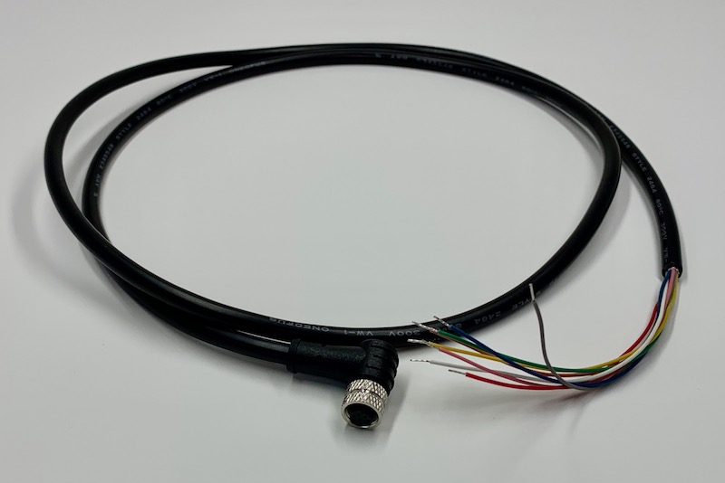
The common use case will be to include a cable gland in your expansion enclosure, pass the wires through the gland, and terminate them on your custom expansion board.
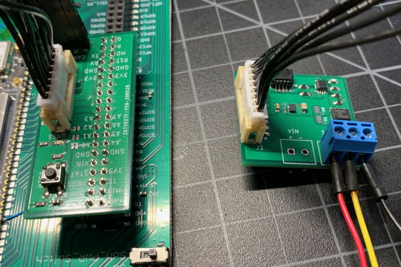
You'd typically connect those wires to your custom expansion board using one of several methods:
- Terminate with pins in a PHR-8 to mate with a B8B-PH on your expansion board
- Terminate with screw terminals on your board
- Terminate by soldering the wires to your board
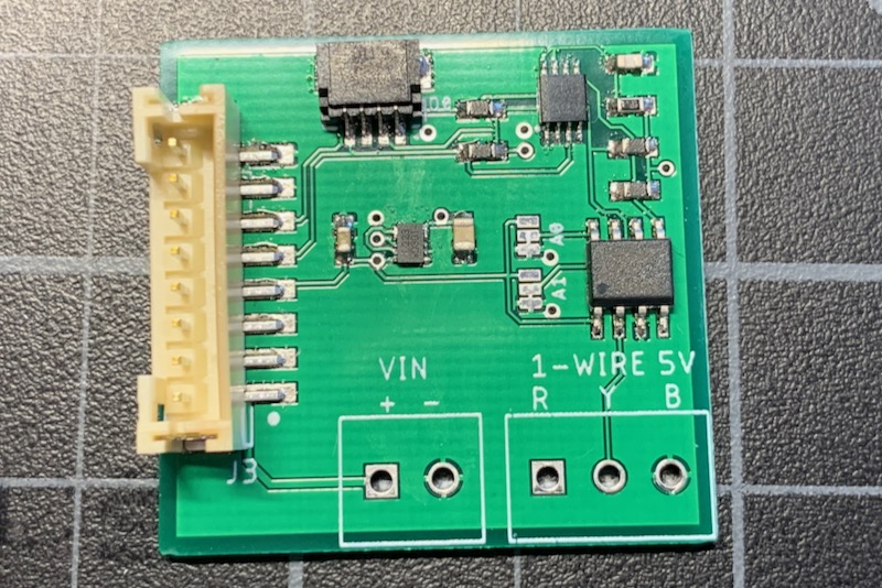
This example design is intended to be a prototype for illustration purposes only. It includes the same B8B-PH connector that is inside the Tracker One on the Tracker Carrier board. This connector is inexpensive and can be attached to the Tracker One Carrier Board or an eval adapter using an easy-to-build PHR-8 to PHR-8 cable:
If you are interested in prototyping designs intended to connect to the Tracker One M8 connector, but want to do it using the Tracker SoM Evaluation Board, you may be interested in this project. It's only a set of design files, BoM, etc. and you'd need to fabricate the board and build it yourself; it's not available as a finished product. It also explains a bit more about how the M8 connector can be used.
Hardware design
Full design
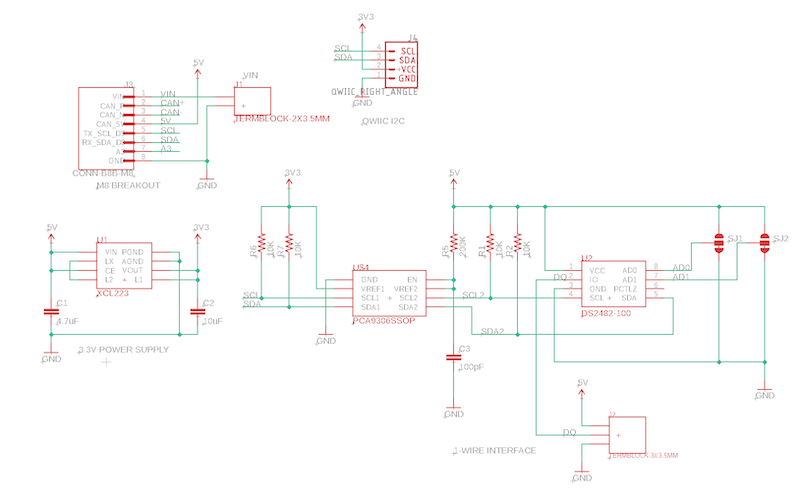
Schematic:
Board:
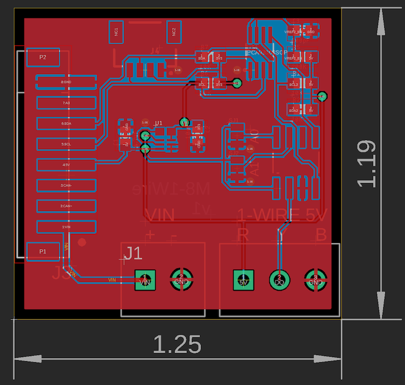
The Eagle CAD files for this design and the Gerber files are included in the eagle subdirectory.
BoM (Bill of Materials)
| Quantity | Part | Description | Example | Cost |
|---|---|---|---|---|
| 1 | C1 | Capacitor Ceramic 4.7uF 6.3V 0603 | Murata GRM188R60J475KE19J | |
| 1 | C2 | Capacitor Ceramic 10uF 16V 0805 | Murata GRM21BR61C106KE15L | |
| 1 | C3 | Capacitor Ceramic 100pF 50V 0603 | Kemet C0603C101J5GACTU | |
| 4 | R1, R2, R6, R7 | Resistor 10K 5% 1/4W 0603 | Panasonic ERJ-PA3J103V | |
| 1 | R5 | Resistor 200K 1% 1/10W 0603 | Panasonic ERJ-3EKF2003V | |
| 1 | J3 | Conn SMD 8 position 2.00mm (optional) | JST B8B-PH-SM4-TB(LF)(SN) | $1.00 |
| 1 | U1 | XCL224 3.3V regulator | Torex XCL224A333D2-G | $ 2.43 |
| 1 | U2 | DS2482-100 8-SOIC | Maxim | $1.54 |
| 1 | U4 | PCA9306SSOP | TI | $0.67 |
| 1 | J4 | QWIIC JST 4-pin 1mm | Sparkfun | $0.50 |
| 1 | J1 | TERMBLOCK-2X3.5MM (optional) | On Shore OSTTE020161 | $0.67 |
| 1 | J2 | TERMBLOCK-3X3.5MM | On Shore OSTTE020161 | $1.00 |
Regulator
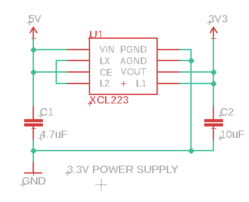
The M8 connector supplies 5V at 370 mA, and can be turned on and off using the CAN_PWR GPIO. There is a boost converter on the Tracker SoM and 5V is available off battery as well as USB and external VIN power.
Since the nRF52840 MCU only supports 3.3V logic levels on I2C, Serial, and GPIO, a 3.3V regulator is often required. This design uses a Torex XCL223 or XCL224. It's tiny, inexpensive, and does not require an external inductor, which saves space and BoM costs. It's a 700 mA regulator, but you'll be limited to the 370 mA on CAN_5V.
PCA9306
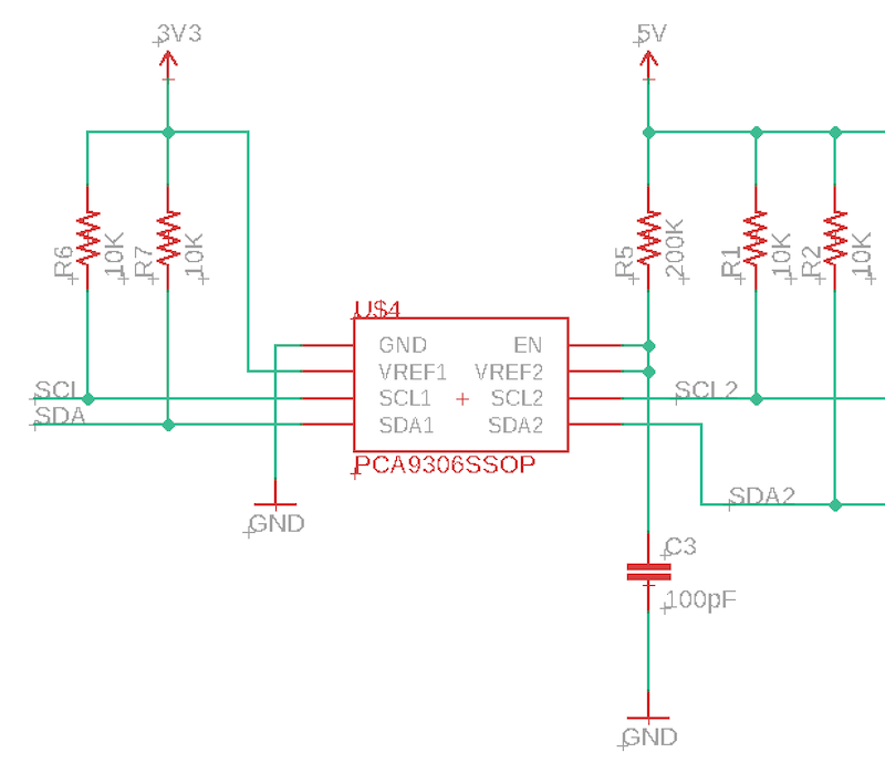
We want to run the 1-Wire bus at 5V because it's more error-tolerant at the higher voltages. It also works with longer wires at the higher voltage. To do this, we also must run the DS2482 at 5V, which requires 5V I2C.
The nRF52 is not 5V tolerant! You cannot directly connect 5V I2C to it!
To get around this issue, we use a PCA9306 I2C level-shifter. This converts between 3.3V and 5V logic. Note that I2C is bi-directional on both pins (SDA and SCL), so you can't just use a simple level-shifter.
Note that I2C requires pull-up resistors, and this design includes two sets, one to 3.3V and one to 5V, on either side of the PCA9306.
DS2482
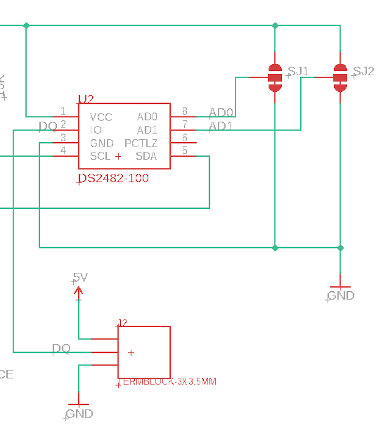
The DS2482 is a hardware I2C to 1-Wire interface. While it is possible to decode 1-Wire in software, on the nRF52 it's not 100% reliable because of interrupt latency. Also doing it in software tends to block the application for long periods time with most current libraries.
Using the DS2482 with the DS2482-RK library makes it very reliable and fully asynchronous. By removing the timing-sensitive code from the MCU, it makes like much easier. It handles multi-drop and supports both external and parasitic power mode.
One really handy technique with this hardware and library is it supports simultaneous conversion. Getting the temperature on the DS18B20 can take up to 2 seconds depending on the resolution. With this setup you can tell all of the sensors on the 1-Wire bus to grab the temperature simultaneously, then read the value from each sensor individually. This dramatically speeds up conversion time when you have multiple sensors.
Adding sensors
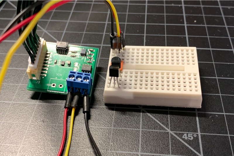
For this prototype design I just used through hole TO-92 package DS18B20 sensors in a solderless breadboard. There are three right next to each other, which isn't a really useful design, but imagine that they are much farther apart in real life.
Qwiic connector
This board includes a Sparkfun Qwiic connector. This allows other I2C devices to be easily chained off this board. This is handy for testing and prototyping, but is not necessary for a production device. You can find out how using Qwiic can make prototyping new sensor designs quick and easy on this page.
Firmware
Getting the Tracker Edge firmware
You can download a complete project for use with Particle Workbench as a zip file here:
Version:
- Extract tracker-an012.zip in your Downloads directory
- Open the tracker-an012 folder in Workbench using File - Open...; it is a pre-configured project directory.
- From the Command Palette (Command-Shift-P or Ctrl-Shift-P), use Particle: Configure Project for Device.
- If you are building in the cloud, you can use Particle: Cloud Flash or Particle: Cloud Compile.
- If you are building locally, open a CLI window using Particle: Launch CLI then:
particle library copy
Manually
The Tracker Edge firmware can be downloaded from GitHub:
https://github.com/particle-iot/tracker-edge
You will probably want to use the command line as there are additional commands you need to run after cloning the source:
git clone https://github.com/particle-iot/tracker-edge
cd tracker-edge
git submodule update --init --recursive
- Open Particle Workbench.
- From the command palette, Particle: Import Project.
- Run Particle: Configure Workspace for Device, select version 1.5.4-rc.1, 2.0.0-rc.3, or later, Tracker, and your device.
- Run Particle: Flash application (local).
Make sure you've used the Mark As Development Device option for your Tracker device in your Tracker product. If you don't mark the device as a development device it will be flashed with the default or locked product firmware version immediately after connecting to the cloud, overwriting the application you just flashed.
Add the DS2482 library
From the command palette in Workbench, Particle: Install Library then enter DS2482-RK.
The documentation for the library can be found here.
Customize main.cpp
Digging in
If you're not familiar with the lambda syntax used in this code, the introduction in the DS2482 library will be helpful.
Note that the M8 I2C interface is Wire3 not Wire as you might be used to on other Particle devices where Wire is on pins D0 and D1. On the Tracker M8 connector, Wire3 is on the same physical pins as Serial1 so you can only use one port or the other.
DS2482 ds(Wire3, 0);
In this code, you're limited to 10 devices. If you have more, just change the <10> to a larger number.
DS2482DeviceListStatic<10> deviceList;
We register a Particle function handler scan. If you call this, it will cause the code to re-scan the 1-Wire bus. For efficiency, we only do this at startup and when requested.
Particle.function("scan", scanFunction);
Make sure you call the loop functions for both the tracker and the DS2482 (ds).
Tracker::instance().loop();
ds.loop();
This is the lambda syntax. Note that the part inside, where the Log.info call is executed asynchronously, after the reset completes. Then it does an asynchronous search bus command, and the code inside that is executed after the search bus completes, which takes a few seconds.
DS2482DeviceReset::run(ds, [](DS2482DeviceReset&, int status) {
    Log.info("deviceReset=%d", status);
    DS2482SearchBusCommand::run(ds, deviceList, [](DS2482SearchBusCommand &obj, int status) {

        if (status != DS2482Command::RESULT_DONE) {
            Log.error("DS2482SearchBusCommand status=%d", status);
            return;
        }

        Log.info("Found %u devices", deviceList.getDeviceCount());

        // Force a temperature scan now
        checkLast = millis() - checkPeriod.count();
    });
});
Because it takes a while to get the temperatures we do it periodically and the latest temperature is picked up in the location publish. As before, the inner code is executed asynchronously.
DS2482GetTemperatureForListCommand::run(ds, deviceList, [](DS2482GetTemperatureForListCommand&, int status, DS2482DeviceList &deviceList) {
    if (status != DS2482Command::RESULT_DONE) {
        Log.error("DS2482GetTemperatureForListCommand status=%d", status);
        return;
    }

    Log.info("got temperatures!");

    for(size_t ii = 0; ii < deviceList.getDeviceCount(); ii++) {
        Log.info("%s valid=%d C=%.2f F=%.2f",
                deviceList.getAddressByIndex(ii).toString().c_str(),
                deviceList.getDeviceByIndex(ii).getValid(),
                deviceList.getDeviceByIndex(ii).getTemperatureC(),
                deviceList.getDeviceByIndex(ii).getTemperatureF());
    }

    haveTemperatures = true;
});
If you're monitoring the USB debug serial log, you'll see something like:
0000998614 [app] INFO: GetTemperatureForList status=1
0000998615 [app] INFO: got temperatures!
0000998616 [app] INFO: 8e0000080a5dde28 valid=1 C=25.75 F=78.35
0000998618 [app] INFO: 970000080b049928 valid=1 C=25.19 F=77.34
0000998619 [app] INFO: 880000080b218b28 valid=1 C=25.75 F=78.35
Note that we don't need to have a mutex around the access to deviceList because it's actually done from either ds.loop() or Tracker::instance().loop() and they will never run simultaneously.
Cloud data
In the map view in the console, you should be able to see the additional custom data:
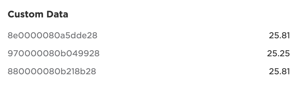
Each DS18B20 sensor has a unique ID assigned at the factory and they are globally unique. This code just uses this ID as the data key, though you could certainly do something fancy and map to more readable names.