
Serial2 on the Photon
Serial2 on the Photon
Normally, the Particle Photon has one UART hardware serial port (Serial1) and the USB serial port (Serial). There is another hardware UART serial port (Serial2), but getting to it is a pain. I don't recommend using it.
Serial2 shares the same pins as the RGB status LED. This means that you have to disable to status LED. This will make debugging a pain in the future. If your code is running, you can mirror the status LED on another LED. Unfortunately that doesn't work when your code is not running, which is really when you need the status LED. Plus, you need to do soldering and remove some SMD resistors from the Photon.
Anyway, you have been warned. Here we go!
Making bottom connections
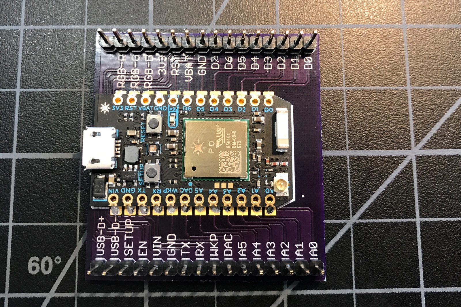
Here's the bottom of the Photon (USB connector on the right).
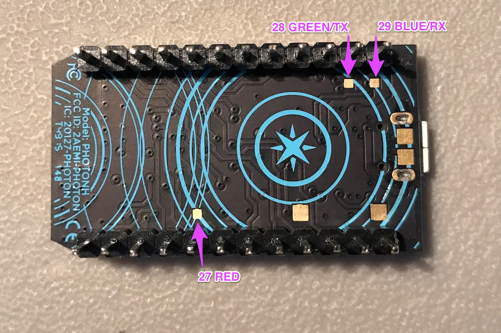
You need to make connections to pins 28 and 29 (the serial port) and optionally pin 27 (red LED). By doing all three, you can attach an external RGB LED to these pins, which may be helpful for debugging.
I used three female header sockets. You may prefer to use a different type of connector. Also, I decided that the pins should be mounted on the USB side, to keep the metal from the connectors out of the keep-away zone under the antenna.
Here is after soldering the leads in place:
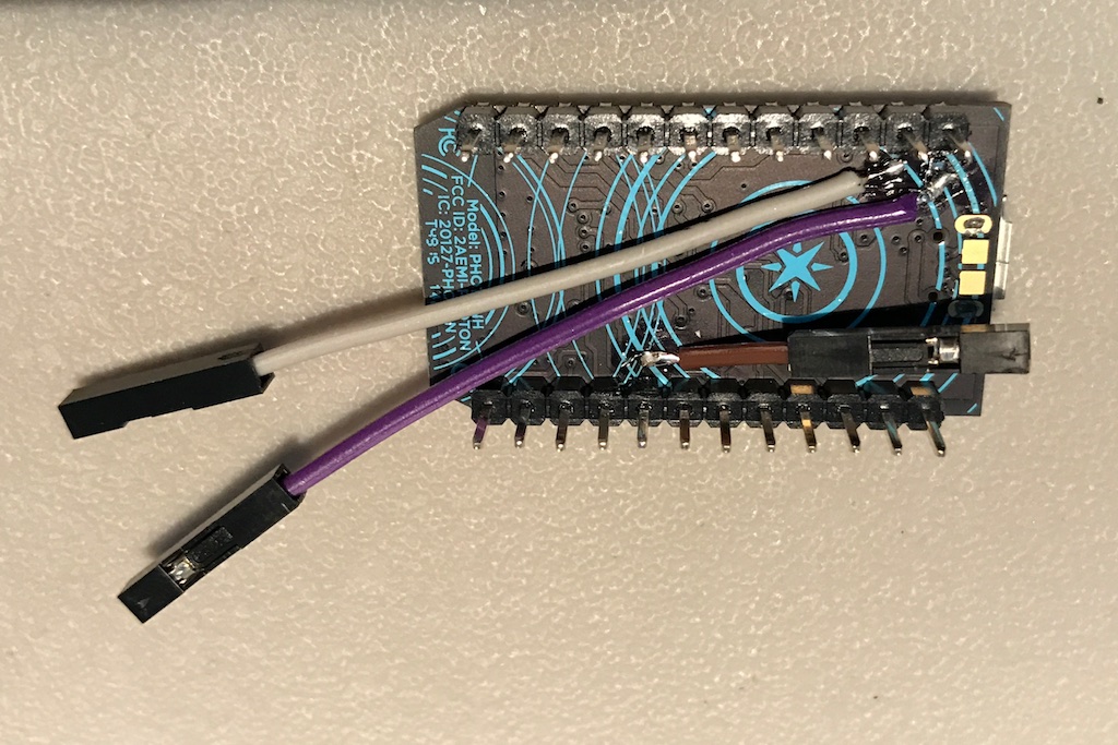
- White Wire: 28 Green LED/TX
- Purple Wire: 29 Blue LED/RX
- Brown Wire: 27 Red LED
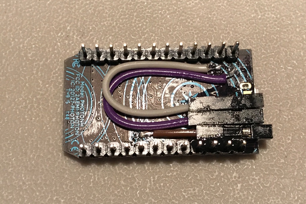
I used epoxy to glue the headers in place. This was more difficult and messier than I anticipated.
There is a much better way of doing this at the end of the document!
Testing out the LED
One advantage of making all three connections is that you can verify your wiring by using an external common anode RGB LED. I used this one from Adafruit but any common anode LED should work.
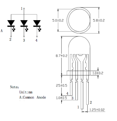
Left to right when positioned as shown above (flat side on right, longest lead is second from right):
- 4 = Blue
- 3 = Green
- 1 = Common Anode (longest lead)
- 2 = Red
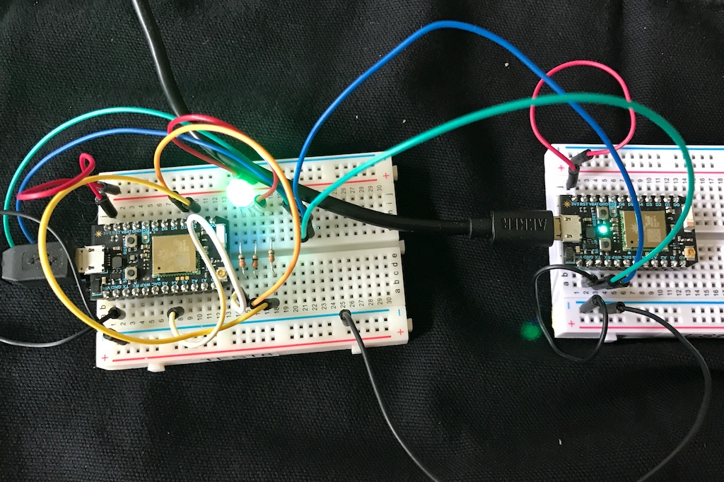
Here is the external LED connected to the pins:
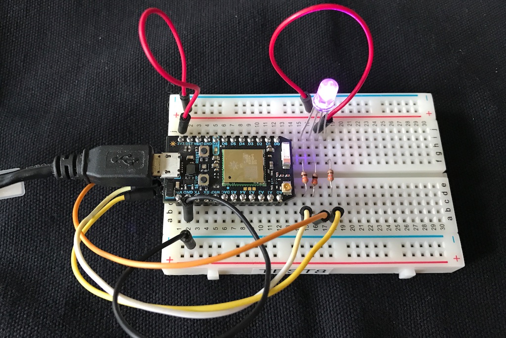
- Orange wire: Photon pin 28 to LED pin 4, blue
- White wire: Photon pin 29 to LED pin 3, green
- Yellow wire: Photon pin 27 to LED pin 2, red
There is also a 330 ohm resistor on each of the 3 cathodes.
With any luck, everything will be working properly, verifying the connections on the bottom are good and you didn't break anything.
Disconnecting the built-in LED
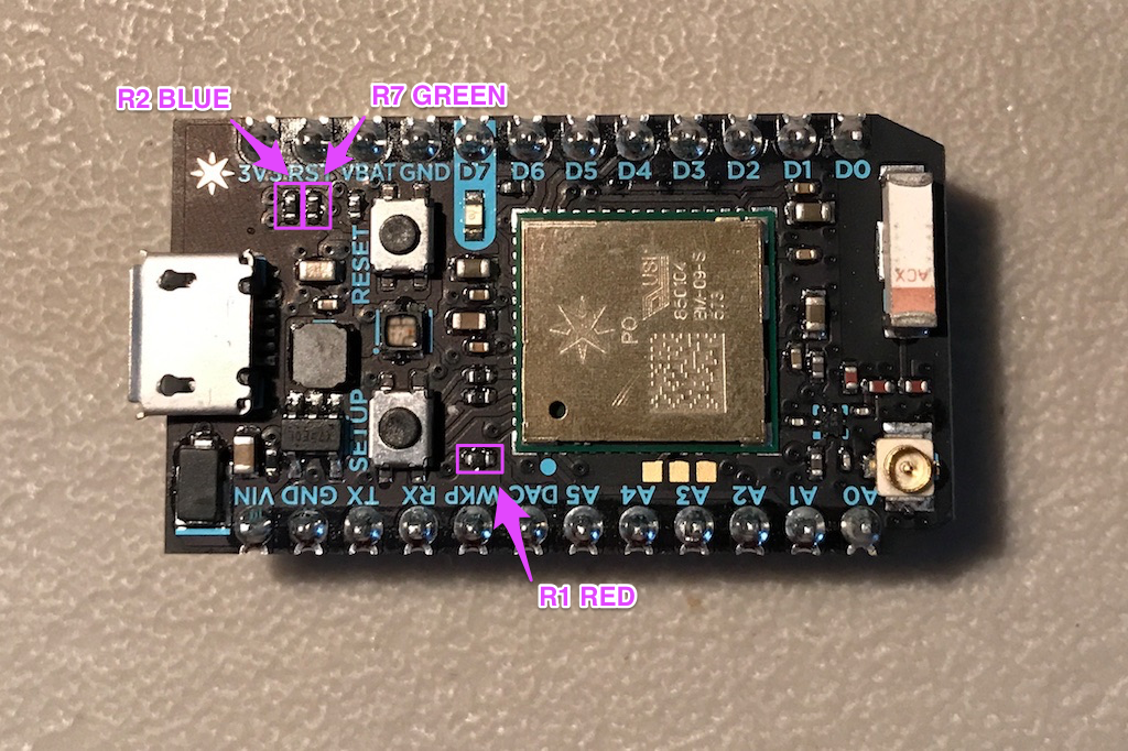
Here's where things get more destructive. You need to disconnect the built-in RGB LED when using Serial2 because otherwise the TX and RX pins will be connected via the LED, and data corruption will likely result. The easiest and safest way to do this is to remove the 3 current limiting resistors R1, R2, and R7.
If you have an SMD hot air rework station, it would be easy to remove these resistors.
In theory you should be able to remove them with a soldering iron. I had trouble doing this, so I used a drill press with a 1/16" bit and the stop set to make sure I didn't drill into the circuit board.
Here's the Photon with the resistors removed:
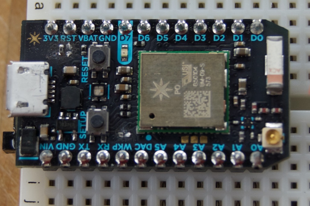
It took a few tries, but you can tell you did it successfully when you boot up and the status LED doesn't light up.
Using the alternate status LED (0.6.1 and later)
This should set the alternate status LED to work automatically from the boot loader with 0.6.1 and later.
STARTUP(RGB.mirrorTo(D2, D3, A4, true, true));

void setup() {
}

void loop() {
}
Using the alternate status LED (0.6.0 and earlier)
To use the status LED on different pins, you must choose other pins that have PWM support. I selected:
- D2: Red LED (yellow wire)
- D3: Green (orange wire)
- A4: Blue (white wire)
The documentations for tone more details of which pins you can use. I purposely avoided D0/D1 since I2C can be handy, and TX/RX since why would to go through the insanity if you didn't need both UART serial ports.
And here's the sample code to test out the LED on the new pins:
#include "Particle.h"

#ifndef SYSTEM_VERSION_v620
SYSTEM_THREAD(ENABLED); // System thread defaults to on in 6.2.0 and later and this line is not required
#endif

// These must be PWM compatible pins, all on different timers. See:
// https://docs.particle.io/reference/device-os/firmware/photon/#tone-
const int RED_PIN = D2;
const int GREEN_PIN = D3;
const int BLUE_PIN = A4;

// LED is a common anode RGB LED, like:
// https://www.adafruit.com/products/159
//
// (    LED   ]  <- flattened side
//  |  |  |  |
//  4  |  |  |
//     3  |  2
//        1
// Left to right:
// 4 = Blue
// 3 = Green
// 1 = Common Anode (longest lead)
// 2 = Red

// Forward declaration
void ledChangeHandler(uint8_t r, uint8_t g, uint8_t b);

void setup() {
    Serial.begin(9600);

    pinMode(RED_PIN, OUTPUT);
    pinMode(GREEN_PIN, OUTPUT);
    pinMode(BLUE_PIN, OUTPUT);
    RGB.onChange(ledChangeHandler);

}

void loop() {
}

void ledChangeHandler(uint8_t r, uint8_t g, uint8_t b) {
    analogWrite(RED_PIN, 255 - r);
    analogWrite(GREEN_PIN, 255 - g);
    analogWrite(BLUE_PIN, 255 - b);
}
Using the serial port
Of course the whole reason to do this was to use the Serial2 port.
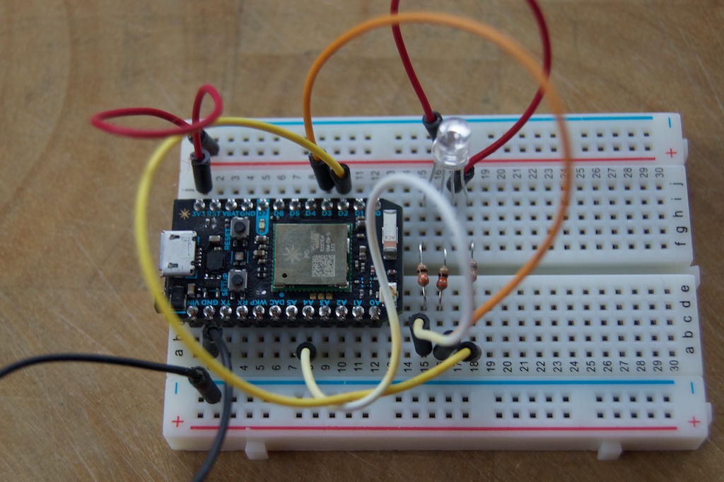
When you're looking at the modified Photon from the USB port side for serial port use:
- Serial2 TX (green wire)
- Serial2 RX (blue wire)
- no connection
Here's the code that I ran on the left (modified) Photon:
#include "Particle.h"

#include "Serial2/Serial2.h"

#ifndef SYSTEM_VERSION_v620
SYSTEM_THREAD(ENABLED); // System thread defaults to on in 6.2.0 and later and this line is not required
#endif

// These must be PWM compatible pins, all on different timers. See:
// https://docs.particle.io/reference/device-os/firmware/photon/#tone-
const int RED_PIN = D2;
const int GREEN_PIN = D3;
const int BLUE_PIN = A4;
const size_t READ_BUF_SIZE = 64;

// Forward declaration
void ledChangeHandler(uint8_t r, uint8_t g, uint8_t b);
void processBuffer();

// Global variables
char readBuf[READ_BUF_SIZE];
size_t readBufOffset = 0;

void setup() {
    Serial.begin(9600);
    Serial2.begin(9600);

    pinMode(RED_PIN, OUTPUT);
    pinMode(GREEN_PIN, OUTPUT);
    pinMode(BLUE_PIN, OUTPUT);
    RGB.onChange(ledChangeHandler);
}

void loop() {
    // Read data from serial
    while(Serial2.available()) {
        if (readBufOffset < READ_BUF_SIZE) {
            char c = Serial2.read();
            if (c != '\n') {
                // Add character to buffer
                readBuf[readBufOffset++] = c;
            }
            else {
                // End of line character found, process line
                readBuf[readBufOffset] = 0;
                processBuffer();
                readBufOffset = 0;
            }
        }
        else {
            readBufOffset = 0;
        }
    }

}

void processBuffer() {
    int receivedValue = atoi(readBuf);

    // This program just increments the value sent by the Photon and returns it
    Serial2.printf("%d\n", receivedValue + 1);
}

void ledChangeHandler(uint8_t r, uint8_t g, uint8_t b) {
    // For a common anode LED, you need to use
    analogWrite(RED_PIN, 255 - r);
    analogWrite(GREEN_PIN, 255 - g);
    analogWrite(BLUE_PIN, 255 - b);
}
And the Photon Test2 on the right:
#include "Particle.h"

// Constants
const unsigned long SEND_INTERVAL_MS = 2000;
const size_t READ_BUF_SIZE = 64;

// Forward declarations
void processBuffer();

// Global variables
int counter = 0;
unsigned long lastSend = 0;

char readBuf[READ_BUF_SIZE];
size_t readBufOffset = 0;

void setup() {
    Serial.begin(9600);

    // Serial1 RX is connected to other Photon TX
    // Serial2 TX is connected to other Photon RX
    // Photon GND is connected to other Photon GND
    Serial1.begin(9600);
}

void loop() {
    if (millis() - lastSend >= SEND_INTERVAL_MS) {
        lastSend = millis();

        Serial1.printlnf("%d", ++counter);
        Serial.printlnf("Sent to other Photon: %d", counter);
    }

    // Read data from serial
    while(Serial1.available()) {
        if (readBufOffset < READ_BUF_SIZE) {
            char c = Serial1.read();
            if (c != '\n') {
                // Add character to buffer
                readBuf[readBufOffset++] = c;
            }
            else {
                // End of line character found, process line
                readBuf[readBufOffset] = 0;
                processBuffer();
                readBufOffset = 0;
            }
        }
        else {
            Serial.println("readBuf overflow, emptying buffer");
            readBufOffset = 0;
        }
    }

}

void processBuffer() {
    Serial.printlnf("Received from other Photon: %s", readBuf);
}
And the output from Test2:
particle serial monitor /dev/cu.usbmodemFD1141
Opening serial monitor for com port: "/dev/cu.usbmodemFD1141"
Sent to other Photon: 1
Received from other Photon: 2
Sent to other Photon: 2
Received from other Photon: 3
Sent to other Photon: 3
Received from other Photon: 4
Sent to other Photon: 4
Received from other Photon: 5
Sent to other Photon: 5
Received from other Photon: 6
Better way of making bottom connections
There is a much better way of making the bottom connections, as well. Using the "no headers" version of the Photon, it can be surface mounted on a printed circuit board:
This is just a test board that exposes all of the bottom connections as well as the standard Photon pins. This works best if you have a reflow oven to bake the Photon onto the circuit board, as it's impossible to hand-solder to the bottom pads in the SMT configuration.
The standard Eagle footprints for the SMT version of the Electron include the bottom pads.