
Watchdog timers
You can download the files associated with this app note as a zip file.
Introduction
A Watchdog Timer is designed to rescue your device should an unexpected problem prevent code from running. This could be the device locking or or freezing due to a bug in code, accessing a shared resource incorrectly, corrupting memory, and other causes.
On Gen 3 devices using Device OS 5.3.0 and later, and Gen 4 devices, it is possible to enable the hardware watchdog timer in the nRF52840 or RTL872x MCU. This is available when running in normal operating mode, and is not used in DFU or safe mode. See hardware watchdog for more information. Using this is effective and eliminates the need for an external hardware watchdog.
Device OS also includes a software-based watchdog, ApplicationWatchdog, that is based on a FreeRTOS thread. It theoretically can help when user application enters an infinite loop. However, it does not guard against the more problematic things like deadlock caused by accessing a mutex from multiple threads with thread swapping disabled, infinite loop with interrupts disabled, or an unpredictable hang caused by memory corruption. Only a hardware watchdog can handle those situations.
This application note will discuss two different watchdog timer implementations:
- Simple hardware watchdog using a TPL5010
- An advanced watchdog and real-time clock using an Abracon AB1805
By itself, a hardware watchdog should be able to recover from most device-lockup issues including when the status LED becomes a solid color (such as solid cyan or solid red). It does not, however, guarantee that a device will always be able to reboot and connect to cellular (or Wi-Fi). Some more techniques are listed in the advanced watchdog section for dealing with that.
A hardware watchdog will not help with problems caused by a bad power supply. Either brown-outs caused by too small of a voltage regulator or battery, or bad power caused by loose connections (such as a bad USB cable) are a different class of problems than the watchdog will generally not help with.
Finally, a hardware watchdog is intended to be a last-resort. Because firmware updates occur in a context where the watchdog cannot be serviced, it's best to have a watchdog timeout of 4 to 6 minutes. You should code as defensively as possible to prevent the watchdog from being needed.
Simple watchdog - TPL5010
The Texas Instruments TPL5010 is a simple watchdog timer that allows the device to be reset after a set period. The design here uses a 4 minute period, but it's adjustable using a resistor. It requires one GPIO to service ("pet" or "tickle") the watchdog and reset the timer. It also connects to the RESET line to reset the device when the watchdog period expires.
One issue with this simple design is that it is not able to reset the watchdog timer right before starting a software update. Thus there is a possibility that the device will watchdog reset during the installation of an update. This should, in general, not harm the device and upon reset the installation will be attempted again, this time with the watchdog timer reset so it should complete before the timeout period (assuming a timeout of at least 4 minutes).
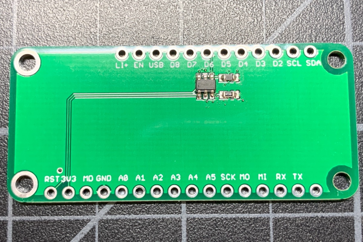
FeatherWing - TPL5010
This design is a simple FeatherWing for the TPL5010. You probably won't want to build this exact board, as it's mostly empty. Instead, you would just add the watchdog features to your own FeatherWing or other peripherals. Still, the Eagle CAD schematic and board files are included in the eagle subdirectory.
Schematic and board - TPL5010
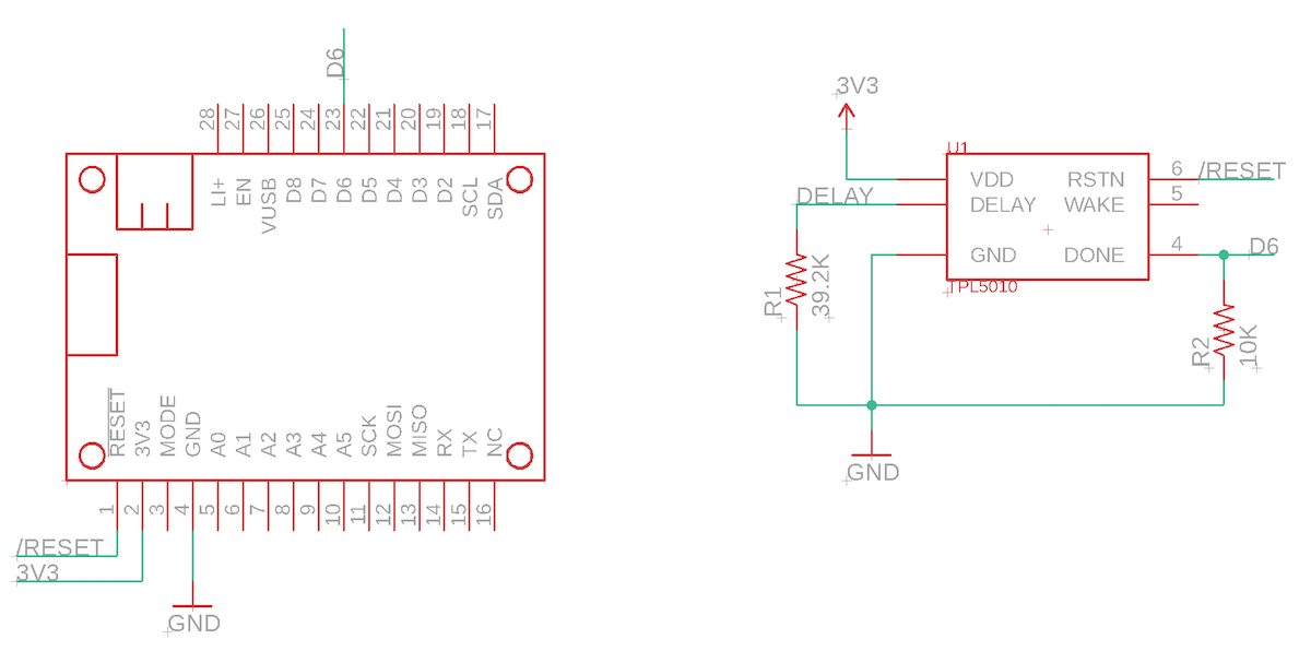
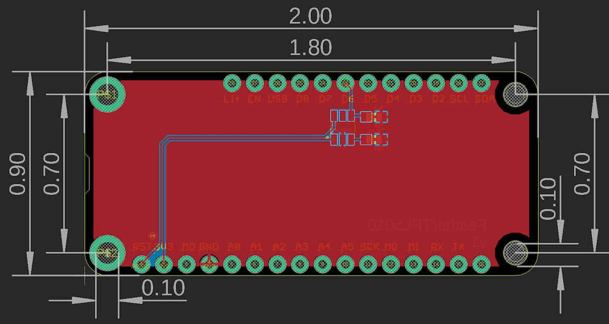
The Eagle files are in the eagle/FeatherTPL5010 directory.
BoM (Bill of Materials) - TPL5010
| Quantity | Part | Description | Example | Cost |
|---|---|---|---|---|
| 1 | U1 | IC OSC PROG TIMER TSOT23-6 | TI TPL5010DDCR | $0.89 |
| 1 | R1 | RES SMD 39.2K OHM 1% 1/10W 0603 | Panasonic ERJ-3EKF3922V | $0.10 |
| 1 | R2 | RES SMD 10K OHM 5% 1/4W 0603 | Panasonic ERJ-PA3J103V | |
| Male Header Pins (0.1") | Sullins PRPC040SAAN-RC |
While this design used a 39.2K resistor for a 4 minute watchdog period, you may want to use a more commonly available 47K resistor for a 6 minute watchdog period.
Hardware design - TPL5010
The TPL5010 has a somewhat complicated timing diagram:
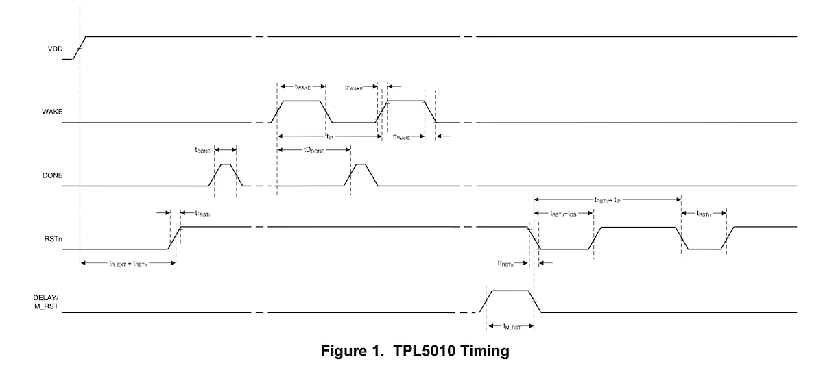
In practice, however, you don't really need to wait for the WAKE pulse to toggle the DONE line. Doing so would require two GPIO, an interrupt handler, and some unnecessary code. Since the TPL5010 ignores DONE pulses that have already occurred during the WAKE cycle you can just do it periodically and ignore WAKE. This saves a GPIO and code. The sample code toggles DONE every 2 minutes with a 4 minute watchdog period. The WAKE PIN is not connected.
The TPL5010 datasheet shows a complex formula for calculating the resistance between DELAY/M_RST and GND. As the period is not particularly critical, you can choose an available value close to the period you desire. The design above is for 4 minutes (39.2K) but you may want to use delay of a little more than 6 minutes (47K) for a extra time for software updates and also a more easily sourced resistor. Watchdog periods of less than 4 minutes are not recommended due to the amount of time necessary to complete a firmware update. A period of 4 - 10 minutes is generally appropriate.
| Duration | Calculated resistance |
|---|---|
| 1 min | 22.02 KΩ |
| 2 min | 29.35 KΩ |
| 3 min | 34.73 KΩ |
| 4 min | 39.11 KΩ |
| 5 min | 42.90 KΩ |
| 6 min | 46.29 KΩ |
| 7 min | 49.38 KΩ |
| 8 min | 52.24 KΩ |
| 9 min | 54.92 KΩ |
| 10 min | 57.44 KΩ |
| 20 min | 77.57 KΩ |
| 30 min | 92.43 KΩ |
| 40 min | 104.67 KΩ |
| 50 min | 115.33 KΩ |
| 60 min | 124.91 KΩ |
The DONE pin handles servicing or tickling the watchdog timer. If you don't pulse the DONE pin in each watchdog timer period, the device will reset. The DONE pin is normally LOW, and must be pulsed HIGH for 100 ns. There is a 10K pull-down resistor on the DONE pin and it is connected to GPIO D6. The pull-down is necessary because the MCU defaults to having pins in INPUT (high-impedance) mode, which would cause DONE to float. Floating confuses the TPL5010 and may cause it to erroneously reset.
Firmware - TPL5010
The TPL5010 does not require a separate library - it just uses a single GPIO.
#include "Particle.h"

#ifndef SYSTEM_VERSION_v620
SYSTEM_THREAD(ENABLED); // System thread defaults to on in 6.2.0 and later and this line is not required
#endif

SerialLogHandler logHandler;

const pin_t WATCHDOG_PIN = D6;
const std::chrono::milliseconds WATCHDOG_PERIOD = 2min;

void serviceWatchdog();

void setup() {
    System.enableFeature(FEATURE_RESET_INFO);
    pinMode(WATCHDOG_PIN, OUTPUT);

    // Uncomment to make it easier to see the serial logs at startup
    // waitFor(Serial.isConnected, 15000);
    // delay(1000);

    if (System.resetReason() == RESET_REASON_PIN_RESET) {
        Log.info("RESET_REASON_PIN_RESET: either RESET or hardware watchdog");
    }
}

void loop() {
    // Call this from every loop(). Also call it from any place where you are blocking
    // for an extended period of time.
    serviceWatchdog();
}


void serviceWatchdog() {
    static unsigned long lastWatchdogMillis = 0;

    if (millis() - lastWatchdogMillis >= WATCHDOG_PERIOD.count()) {
        lastWatchdogMillis = millis();

        // Log.info("service watchdog");

        // Actual minimum high period is 100 ns but there is no nanosecond delay
        // in Device OS. 1 microsecond is still a very short period of time so
        // blocking should not be an issue here as it only happens once every
        // 2 minutes.
        digitalWrite(WATCHDOG_PIN, HIGH);
        delayMicroseconds(1);
        digitalWrite(WATCHDOG_PIN, LOW);
    }
}
TPL5000
The TPL5000 can also be used with the Photon and P1, and does not require a period-setting resistor. It uses three pins to set the timeout value. Because the maximum timeout is 64 seconds (with all three pins tied to VDD), it's not long enough to get a software update on cellular devices. In general, it's best to use a TPL5010 with a 4 - 6 minute period even for the Photon and P1 devices. You should also not use the TPL5000 with the Argon, as it has much larger system downloads than the Photon and P1.
Advanced watchdog - AB1805
The Abracon AB1805 (and its identical relative, the Ambiq Micro AM1805), is an I2C-connected watchdog and real-time clock chip. It has a number of advanced features that make it ideal for use as a watchdog and RTC with Boron and Argon devices. It's also built into the Tracker SoM.
The designs in this section are for simple FeatherWings for the AB1805. You could use these board as-is, add your components to the big empty space on the FeatherWing, or incorporate the circuit onto your own board. The Eagle CAD schematic and board files are included in the eagle subdirectory.
The AB1805 has a number of useful features:
- Programmable wake from sleep
- Deep power-off (powering off the device entirely for a custom period, typically 30 seconds)
- Watchdog reset
- Real-time clock (optional)
- Separate RTC backup battery or super-capacitor (optional)
The Gen 3 nRF52 MCU has a number of sleep modes. While the nRF52 RTC is enabled in STOP and ULP (ultra-low power) sleep modes, it is disabled in the lowest power mode, HIBERNATE mode. Using an external RTC like the AB1805 makes it possible to use its RTC to wake by time and reset the MCU clock after wake, without needing to get the time from the cloud.
The RTC in Gen 4 devices (RTL872x MCU) continues to operate in hibernate sleep mode, so an external hardware clock is not require to wake based on time in hibernate sleep mode. You still may want to use an external RTC if you want the clock to be preserved across device reset and power down.
There are two versions of this board:
- FeatherAB1805-Li is supplied by the LiPo battery
- FeatherAB1805-SC uses a super-capacitor for the RTC backup power and deep power-off
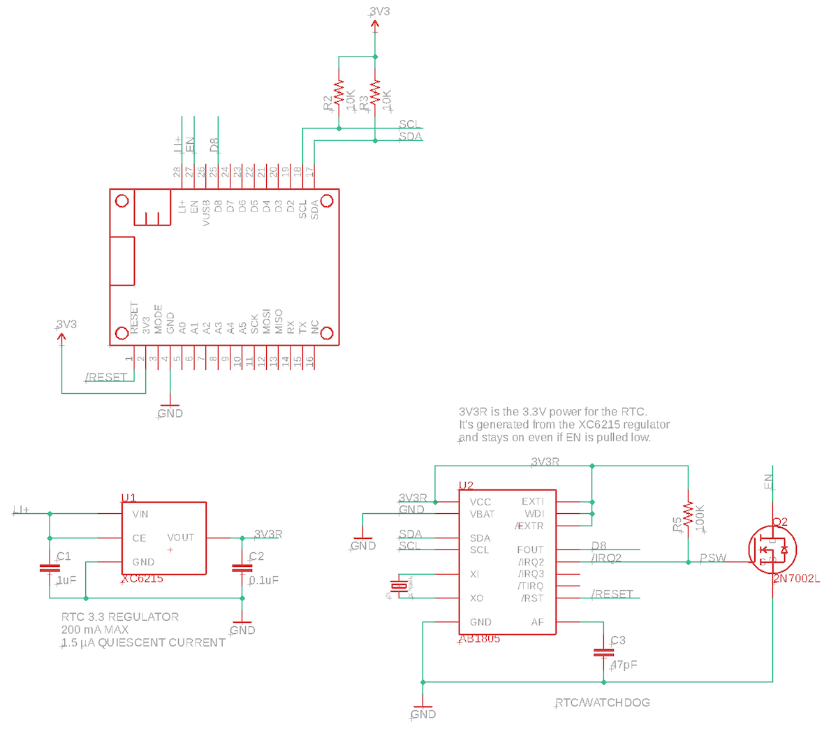
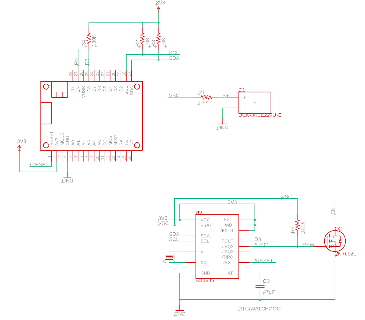
Connections between AB1805 and MCU
The AB1805 is connected like this (from the FeatherAB1805-SC schematic):
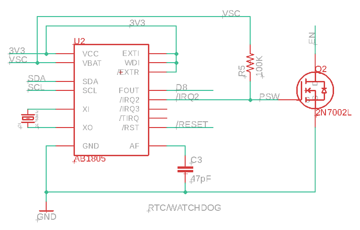
Of note:
- FOUT (nIRQ) is connected to MCU D8 to provide interrupts between the AB1805 and MCU. You can use other pins instead of D8.
- nIRQ2 (PSW) is connected to an N-channel MOSFET to control the MCU/Feather EN pin (low = power down)
- nRST is connected to the MCU /RESET line (active low).
About the EN pin
The EN pin on Gen 3 Feather devices (Argon, Boron) is used to power down the device (HIGH = enabled or powered on, LOW = power off). There is an internal 100K pull-up on the EN pin, and pulling this pin LOW will turn off a load switch that powers down both the cellular modem (on the Boron) as well as the 3V3 regulator that the nRF52840 MCU is connected to. Here's the Boron schematic:
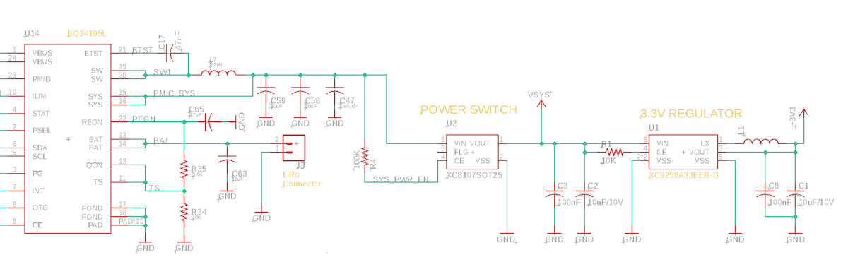
Some care must be used with EN as the 100K pull-up is connected to the SW output of the bq24195 and thus can be as high as 4.2V. Thus you generally should not connect it to a 3.3V GPIO. Instead, this app note example connects it to an N-channel MOSFET (2N7002) which allows the AB1805 to pull the EN line low without exposing the AB1805 PSW pin to the 4.2V signal.
The nIRQ2/PSW pin is also a confusing in itself. There are two uses cases for this pin: connecting to a MOSFET to control external power and also to directly power a low-power circuit or MCU. It's intended to be a low-side switch, and thus:
| State | nIRQ2/PSW |
|---|---|
| Not Powered (Off) | Open |
| Powered (On) | LOW (connected to VSS/GND) |
The app note circuit adds a 100K pull-up to to the nIRQ2/PSW pin, thus resulting in this signal to the gate of the N-channel MOSFET (2N7002):
| State | nIRQ2/PSW with pull-up |
|---|---|
| Not Powered (Off) | HIGH |
| Powered (On) | LOW |
Finally, the EN line:
| State | EN line |
|---|---|
| Not Powered (Off) | LOW |
| Powered (On) | Open (powered on) |
Note that the default power-up state of the AB1805 nIRQ2/PSW is to pull this line LOW, so by default the EN line will allow the Particle device to power on. The not powered state is referred to as AB1805 sleep mode, and it works even if the AB1805 is not fully powered and is only powered by VBAT.
You should only use the EN pin for deep power down in extenuating circumstances, such as extended failure to connect. Under normal circumstances, a cloud session can be resumed when waking up from sleep. However, on Gen 3 devices, if you remove power using EN, the retained memory is cleared, as is the session context, so renegotiation is required. This may use 5K to 6K of data on every deep power down and also lengthen the amount of time required to connect, using more power.
Additionally:
- Powering down the modem unexpectedly can cause modem bricking in rare cases. There is no way to recover from this.
- If period is too short, it can cause aggressive reconnection. This is especially problematic if the device enters rolling reboot due to a bug in the user firmware.
- Possible issues with OTA, depending on how its implemented. Resumable OTA requires that the system go to sleep gracefully in order to properly synchronize the download state.
About the EN pin and RESET
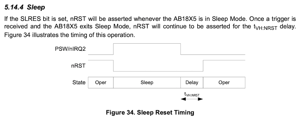
While using the EN pin on the Feather will completely power down the MCU, you must be careful of one special case:
If you have externally powered circuits that apply power to GPIOs when EN is LOW, this flow of current back into the MCU from the GPIO can prevent the nRF52 MCU from resetting!
To eliminate this problem the AB1805 is configured to also bring nRESET low when in sleep (EN power down) mode. This assures that the MCU will always reset, even if there is leakage current.
This method is preferable to connecting EN and RESET together by wire. The problem with physically connecting EN and RESET together is that pressing the RESET button on the Boron will briefly bring EN low in this case. This will remove power from the modem. Normally, in Device OS 2.0.0 and later, RESET allows the modem to stay connected across System.reset() and the RESET button for faster reconnection. Also, a very short press of the RESET button could brown out the cellular modem without fully resetting it. Thus the separate software control of EN and RESET is preferable.
Watchdog configuration
The AB1805 Watchdog has a maximum of 124 seconds. This is less than the 4 - 6 minutes we recommend, however this is acceptable because:
- The watchdog defaults to off at power-up, so if you cold boot into safe mode the watchdog will be off.
- The firmware detects a system reset and will turn the watchdog off manually before reset. This takes care of the firmware update case as well.
Remember that the watchdog will continue to run even if you enter sleep mode! You must always turn off the watchdog before calling System.sleep() by using:
ab1805.stopWDT();
If you are using STOP or ULTRA_LOW_POWER, execution continues after System.sleep() returns, and it's recommended that you call:
ab1805.resumeWDT();
ab1805.updateWakeReason();
FeatherWing - AB1805-Li
This design is intended to be used with a LiPo battery connected. It will not work correctly when only powered by USB! However, if you do always have a LiPo the design is smaller and less expensive.
The AB1805-SC (supercap) version can be used when powered by USB or LiPo.
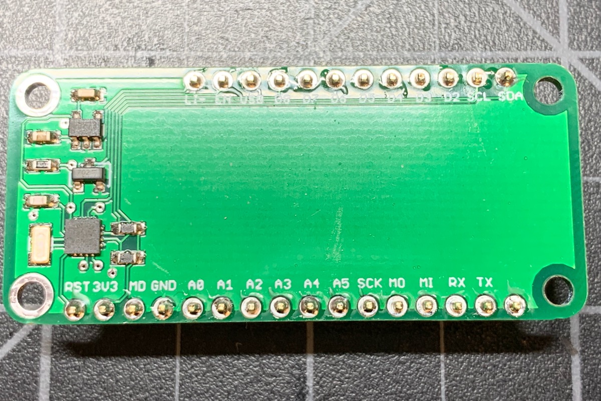
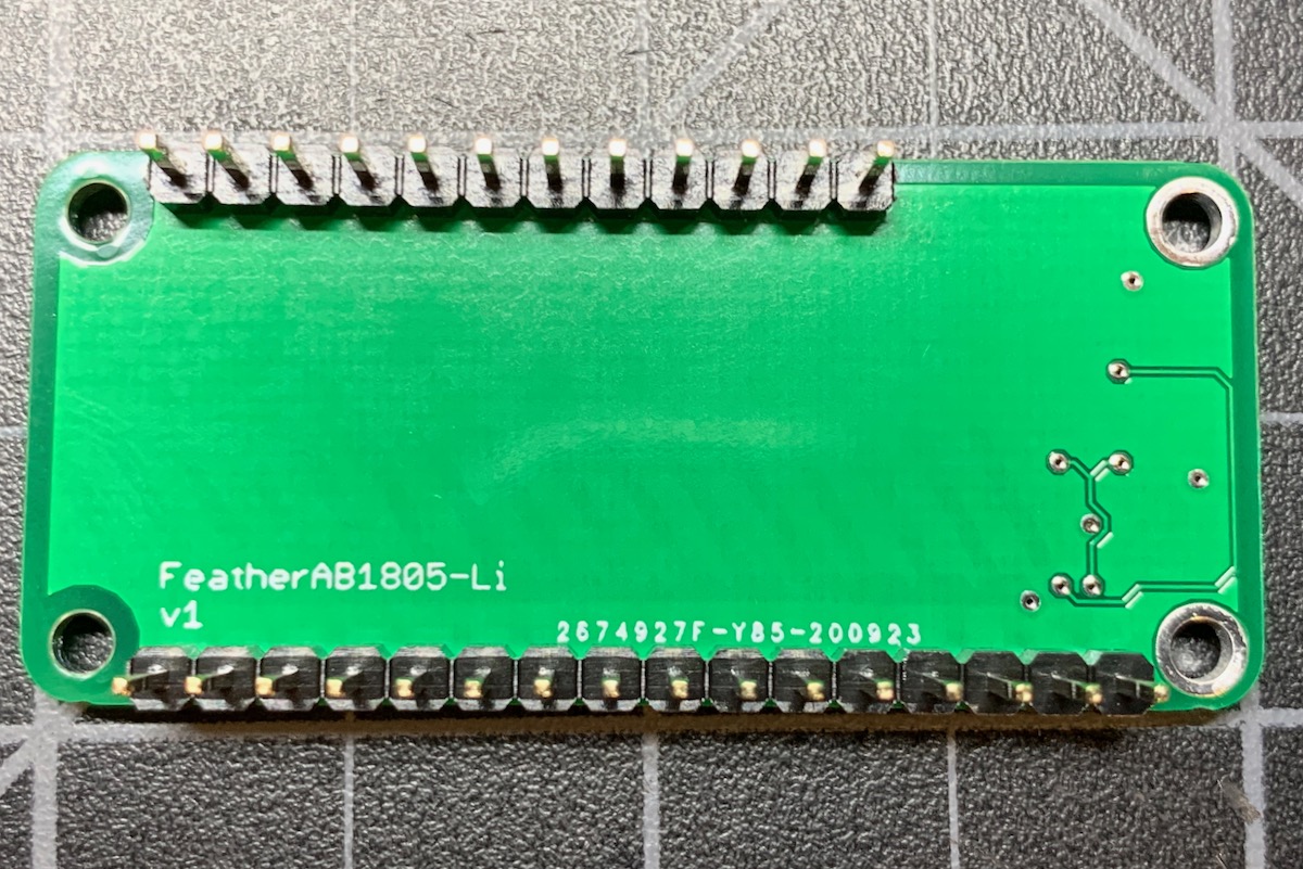
These pictures are of v1 of the board.
Schematic and Board - AB1805-Li
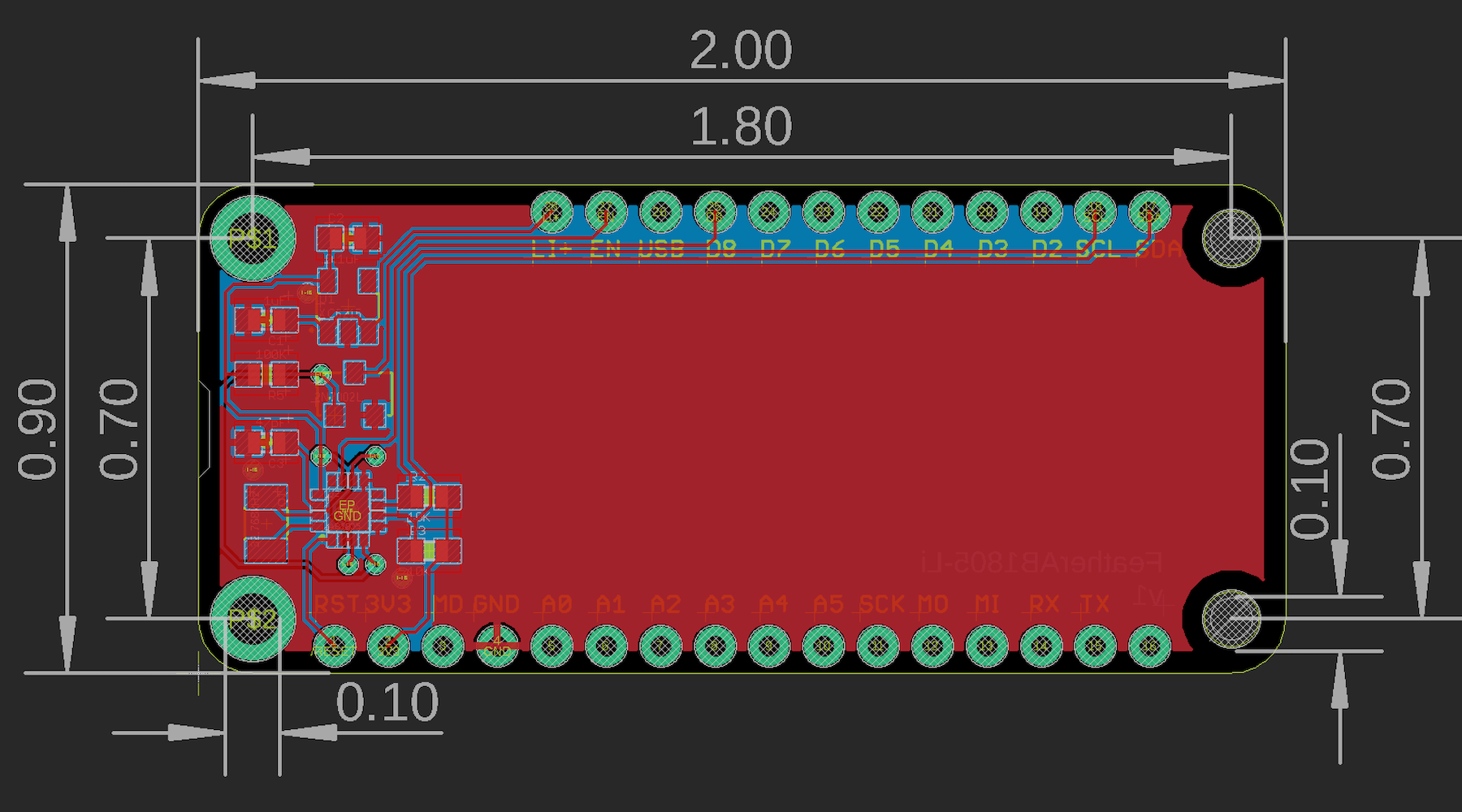
The Eagle files are in the eagle/FeatherAB1805-Li directory.
- V2 of the board added R1, a 100K pull-up from D8 to 3V3. This was present on the FeatherAB1805-Sc board, but missing from the Li board.
BoM (Bill of Materials) - AB1805-Li
| Quantity | Part | Description | Example | Cost |
|---|---|---|---|---|
| 1 | C1 | CAP CER 1UF 25V X7R 0603 | Samsung CL10B105KA8NNNC | |
| 1 | C2 | CAP CER 0.1UF 25V X7R 0603 | Samsung CL10B104KA8NNNC | |
| 1 | C3 | CAP CER 47PF 100V C0G/NP0 0603 | Murata GCM1885C2A470FA16D | |
| 2 | R2, R3 | RES SMD 10K OHM 5% 1/4W 0603 | Panasonic ERJ-PA3J103V | |
| 2 | R1, R5 | RES SMD 100K OHM 1% 1/10W 0603 | Panasonic ERJ-3EKF1003V | |
| 1 | Q1 | CRYSTAL 32.7680KHZ 6PF SMD | Abracon ABS07-120-32.768KHZ-T | $0.77 |
| 1 | Q2 | MOSFET N-CH 60V 0.115A SOT-23 | On Semiconductor 2N7002LT1G | |
| 1 | U1 | IC REG LINEAR 3.3V 200MA SOT25 | Torex XC6215B332MR-G | $0.71 |
| 1 | U2 | IC RTC CLK/CALENDAR I2C 16-QFN | Abracon LLC AB1805-T3 | $1.79 |
| Male Header Pins (0.1") | Sullins PRPC040SAAN-RC |
Hardware design - AB1805-Li
Of note in this design is the use of a separate regulator to power the AB1805. The Torex XC6215B332MR-G is inexpensive ($0.71 in single quantities), requires only an input and output capacitor, no inductor. It also has a very low quiescent current.
- 6V max input
- 3.3V output 200 mA
- 1.5µA quiescent current
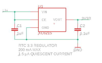
This power supply (3V3R) is connected to VCC on the AB1805 so it will stay fully powered. This is necessary because deep power down mode uses the EN pin to turn off the MCU 3V3 power, so we can't power the AB1805 from 3V3 without external power. The AB1805-SC design, below, uses a supercap instead of a separate regulator.
Software note for Photon 2 - AB1805-Li
If you are using the wake from hibernate sleep feature with the Photon 2, note that the pin next to D7 is D10, but is in the same position as the Boron/Argon D8. If you use the constant WKP the correct pin name will be used, but be aware of this if you hardcode D8 or D10 in your code.
Only the WKP pin can be used to wake the P2, Photon 2, and M-SoM from hibernate sleep. Also, WKP does not support software pull-up while in hibernate sleep mode.
FeatherWing - AB1805-SC
This example is similar to the previous one, except:
- It's powered by 3V3 so it works whether powered by USB, VUSB, or LiPo.
- It has a 250 mF supercap that can power the RTC and also handle the deep powerdown reset mode.
- It does not need the XC6215 3.3 volt regulator that the AB1805-Li uses to power from the LiPo directly.
As the power requirements of the AB1805 are very low, using a supercap is preferable to using a battery. Disposable lithium coil cell batteries (like a CR1220) may have shipping restrictions, and having a separate rechargeable battery may have size and temperature issues.
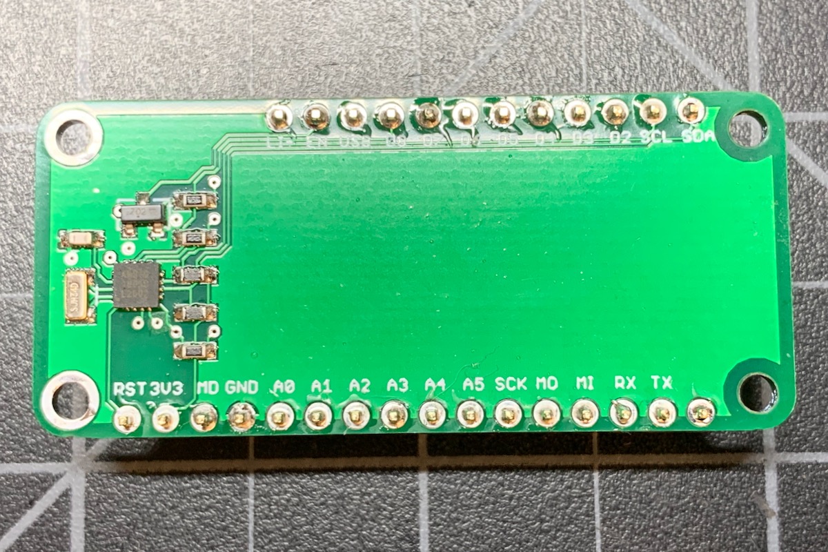
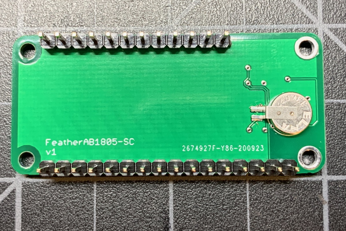
Schematic and board - AB1805-SC
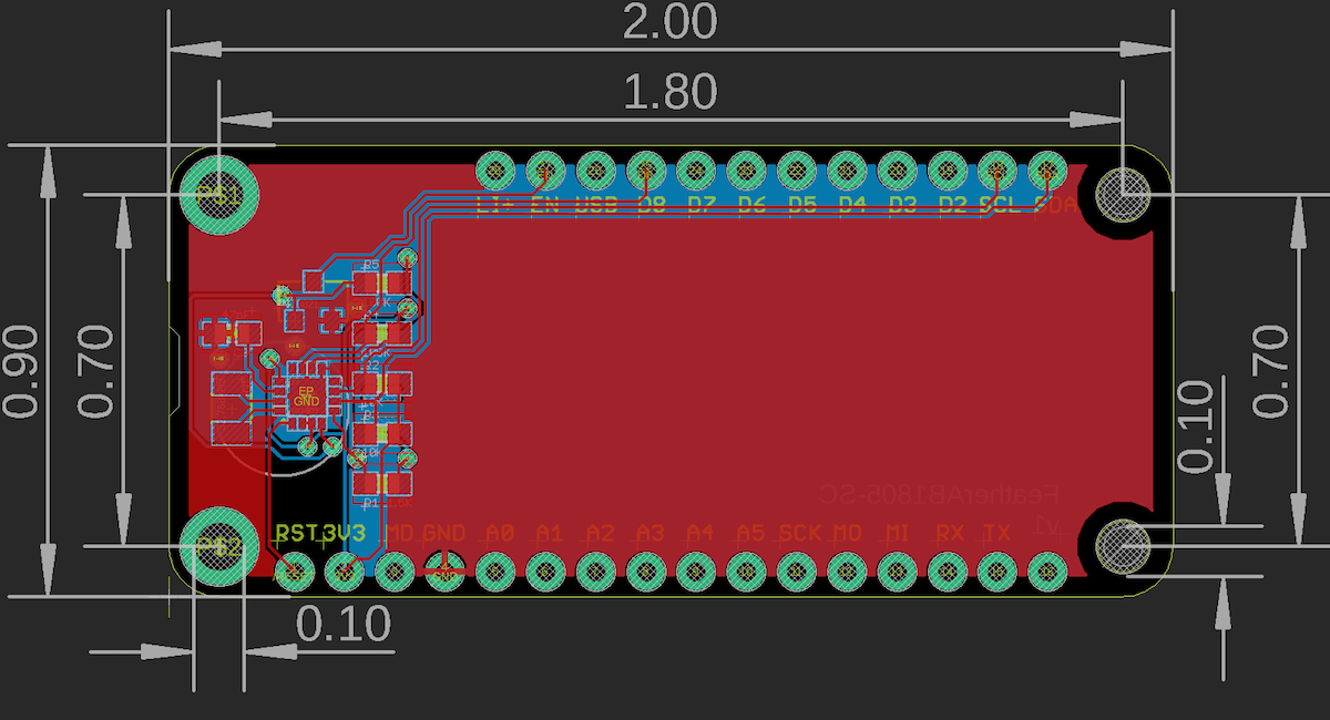
The Eagle files are in the eagle/FeatherAB1805-SC directory.
BoM (Bill of Materials) - AB1805-SC
| Quantity | Part | Description | Example | Cost |
|---|---|---|---|---|
| 1 | C1 | CAP 220MF -20% +80% 3.3V SMD | Elna America DCK-3R3E224U-E | $1.41 |
| 1 | C3 | CAP CER 47PF 100V C0G/NP0 0603 | Murata GCM1885C2A470FA16D | |
| 1 | R1 | RES SMD 1.5K OHM 1% 1/10W 0603 | Panasonic ERJ-3EKF1501V | |
| 2 | R2, R3 | RES SMD 10K OHM 5% 1/4W 0603 | Panasonic ERJ-PA3J103V | |
| 1 | R5 | RES SMD 100K OHM 1% 1/10W 0603 | Panasonic ERJ-3EKF1003V | |
| 1 | Q1 | CRYSTAL 32.7680KHZ 6PF SMD | Abracon ABS07-120-32.768KHZ-T | $0.77 |
| 1 | Q2 | MOSFET N-CH 60V 0.115A SOT-23 | On Semiconductor 2N7002LT1G | |
| 1 | U2 | IC RTC CLK/CALENDAR I2C 16-QFN | Abracon LLC AB1805-T3 | $1.79 |
| Male Header Pins (0.1") | Sullins PRPC040SAAN-RC |
Hardware design - AB1805-SC
Software note for Photon 2 - AB1805-Sc
If you are using the wake from hibernate sleep feature with the Photon 2, note that the pin next to D7 is D10, but is in the same position as the Boron/Argon D8. If you use the constant WKP the correct pin name will be used, but be aware of this if you hardcode D8 or D10 in your code.
Only the WKP pin can be used to wake the P2, Photon 2, and M-SoM from hibernate sleep. Also, WKP does not support software pull-up while in hibernate sleep mode.
Supercap calculations - AB1805-SC
There are several different power consumption values of interest for the AB1805:
| Mode | Current |
|---|---|
| EN low | 40 uA |
| Crystal oscillator | 55 nA |
| RC oscillator w/autocalibration | 22 nA |
| RC oscillator | 14 nA |
This design uses a 250 mF 3.3V super capacitor, which costs about $1.41 in single quantities.
- Elna America DCK-3R3E224U-E
- CAP 220MF -20% +80% 3.3V SMD
- 220mF (EDLC) Supercapacitor 3.3V Coin, Wide Terminals
- Same Sides 200Ohm @ 1kHz 1000 Hrs @ 60°C
To calculate the capacity I used one of the common supercap calculators available on the Internet.
| Parameter | Value |
|---|---|
| Vcapmax | 3.0V |
| Vcapmin | 1.4V |
| Capacitor size | 0.220 Farad |
| Capacitor ESR | 220 ohms |
| iMax | 0.2 uA |
| Operating time | 1,759,951 sec = 20 days |
There are two additional parameters that are configurable when using the AB1805 as a trickle charger for the supercap: the voltage and the series resistance:
| Parameter | Value |
|---|---|
REG_TRICKLE_DIODE_0_6 |
0.6V drop = 2.7V |
REG_TRICKLE_DIODE_0_3 |
0.3V drop = 3.0V |
| Parameter | Value |
|---|---|
REG_TRICKLE_ROUT_11K |
11K output resistance |
REG_TRICKLE_ROUT_6K |
6K output resistance |
REG_TRICKLE_ROUT_3K |
3K output resistance |
The voltage is chosen based on the voltage rating for your supercap, and is also necessary to prevent the voltage from flowing back into the MCU from the supercap. The supercap should only power the RTC VBAT battery input to keep the minimal circuitry powered. The 3.3V supercap selected above can use the 0.3V drop.
The resistance determines how quickly the supercap will charge. There also may be a physical resistor connected in series to the supercap that is used for both charge and discharge. In this design, there is a 1.5K series resistor as recommended in the AB1805 datasheet. When charging, this is combined with a 3K trickle charge resistor to make a 4.5K charge resistance.
To calculate the charge time, the formula: 5RC is typically used.
The C is the supercap size in Farads, or 0.220 F for this cap.
5RC = 5 * 4500 Ω × 0.220 F = 4950 seconds = 1 hr 22 min
This is the maximum time to charge.
I = V/R = 3V / 4500Ω = 0.00066 A = 0.666 mA = 666 uA
This is the maximum amount of current that can flow through the charger. In this case, it's well within the capabilities of 3V3 so it should not be an issue.
Firmware - AB1805-SC
To enable the supercap charger, you call setTrickle(). The parameter are as above to select the diode and resistance. This must be done after ab1805.setup().
ab1805.setTrickle(AB1805::REG_TRICKLE_DIODE_0_3 | AB1805::REG_TRICKLE_ROUT_3K);
Minimal firmware - AB1805
This is just the minimal implement of using the RTC and Watchdog Timer (WDT). Here's the complete code:
#include "AB1805_RK.h"

#ifndef SYSTEM_VERSION_v620
SYSTEM_THREAD(ENABLED); // System thread defaults to on in 6.2.0 and later and this line is not required
#endif
SYSTEM_MODE(SEMI_AUTOMATIC);

SerialLogHandler logHandler;

AB1805 ab1805(Wire);

void setup() {
    // The sample board has D8 connected to FOUT for wake interrupts, though this
    // example does not use this feature.
    ab1805.withFOUT(D8).setup();

    // Reset the AB1805 configuration to default values
    ab1805.resetConfig();

    // Enable watchdog
    ab1805.setWDT(AB1805::WATCHDOG_MAX_SECONDS);

    // Connect to the Particle cloud
    Particle.connect();
}


void loop() {
    // Be sure to call ab1805.loop() on every call to loop()
    ab1805.loop();
}
This example uses the AB1805_RK library. In Particle Workbench, use Particle: Install Library from the command palette. In the Web IDE, add this library from the Libraries icon.
Things to note in this code:
Declare an AB1805 object in your code as a global variable. Only do this once in your main source file. The parameter is the I2C interface the AB1805 is connected to, typically Wire (D0/D1).
AB1805 ab1805(Wire);
In setup(), call the ab1805.setup() method.
ab1805.setup();
Reset the settings on the AB1805. This isn't strictly necessary since it resets the chip to power-on defaults, but it's not a bad idea to be safe:
ab1805.resetConfig();
If you want to use the hardware watchdog, enable it:
ab1805.setWDT(AB1805::WATCHDOG_MAX_SECONDS);
And from loop(), make sure you call the loop method:
ab1805.loop();
The ab1805.loop() method takes care of:
- Serving the watchdog timer.
- Synchronizing the hardware RTC with the cloud time.
- Turning off the watchdog before System.reset() in case an OTA firmware update is in progress.
Typical firmware - AB1805
The example in firmware/01-typical example shows how to:
- Enable the watchdog timer
- Add a memory allocation failure handler
- Do a deep power down after an extended (11 minute) inability to connect to the cloud
This example can be used on either the AB1805-Li or AB1805-SC sample board by changing one line of code to enable the trickle charger or not using ab1805.setTrickle().
This example uses the AB1805_RK library. In Particle Workbench, use Particle: Install Library from the command palette. In the Web IDE, add this library from the Libraries icon.
Full firmware:
#include "AB1805_RK.h"

#ifndef SYSTEM_VERSION_v620
SYSTEM_THREAD(ENABLED); // System thread defaults to on in 6.2.0 and later and this line is not required
#endif
SYSTEM_MODE(SEMI_AUTOMATIC);

SerialLogHandler logHandler;

// This is the maximum amount of time to allow for connecting to cloud. If this time is
// exceeded, do a deep power down. This should not be less than 10 minutes. 11 minutes
// is a reasonable value to use.
const std::chrono::milliseconds connectMaxTime = 11min;

AB1805 ab1805(Wire);
int outOfMemory = -1;
bool cloudConnected = false;
uint64_t cloudConnectStarted = 0;

void outOfMemoryHandler(system_event_t event, int param);

void setup() {
    // Enabling an out of memory handler is a good safety tip. If we run out of
    // memory a System.reset() is done.
    System.on(out_of_memory, outOfMemoryHandler);

    // Optional: Enable to make it easier to see debug USB serial messages at startup
    // waitFor(Serial.isConnected, 15000);
    // delay(1000);

    // Make sure you set up the AB1805 library from setup()!
    ab1805.setup();

    // This is how to check if we did a deep power down (optional)
    AB1805::WakeReason wakeReason = ab1805.getWakeReason();
    if (wakeReason == AB1805::WakeReason::DEEP_POWER_DOWN) {
        Log.info("woke from DEEP_POWER_DOWN");
    }

    // Reset the AB1805 configuration to default values
    ab1805.resetConfig();

    // If using the supercap, enable trickle charging here.
    // Do not enable this for the AB1805-Li example!
    // ab1805.setTrickle(AB1805::REG_TRICKLE_DIODE_0_3 | AB1805::REG_TRICKLE_ROUT_3K);

    // Enable watchdog
    ab1805.setWDT(AB1805::WATCHDOG_MAX_SECONDS);

    // Connect to the Particle cloud
    Particle.connect();
}


void loop() {
    // Be sure to call ab1805.loop() on every call to loop()
    ab1805.loop();

    if (outOfMemory >= 0) {
        // An out of memory condition occurred - reset device.
        Log.info("out of memory occurred size=%d", outOfMemory);
        delay(100);

        System.reset();
    }

    // Monitor the cloud connection state and do a deep power down if a
    // failure to connect exceeds connectMaxTime (typically 11 minutes).
    if (Particle.connected()) {
        if (!cloudConnected) {
            cloudConnected = true;
            uint32_t elapsed = (uint32_t)(System.millis() - cloudConnectStarted);
            Log.info("cloud connected in %lu ms", elapsed);
        }
    }
    else {
        if (cloudConnected) {
            cloudConnected = false;
            cloudConnectStarted = System.millis();
            Log.info("lost cloud connection");
        }
        uint32_t elapsed = (uint32_t)(System.millis() - cloudConnectStarted);
        if (elapsed > connectMaxTime.count()) {
            Log.info("failed to connect to cloud, doing deep reset");
            delay(100);
            ab1805.deepPowerDown();
        }
    }
}

void outOfMemoryHandler(system_event_t event, int param) {
    outOfMemory = param;
}
Out of memory handler
The out of memory handler is a good feature to have in your code. This is different than a check of System.freeMemory(). The out of memory handler is called when an allocation fails and returns NULL. Note that this is not in itself fatal, as your code might then do something to free up some memory and try again. However, in practice, if you are running that low on RAM, a reset is often a reasonable alternative. C/C++ do not have garbage collection and thus it's possible for memory to be fragmented into unusably small chunks. A reset is the only way to clean this up in most cases. Note that on Gen 2 devices and Gen 3 devices with Device OS 2.0.0 and later, a System.reset() should be fast because it stays connected to the cellular modem.
You need a global variable, because it's not a good idea to reset directly from the system event handler.
int outOfMemory = -1;
You need to register the out of memory handler from setup():
System.on(out_of_memory, outOfMemoryHandler);
The handler function just sets the global variable:
void outOfMemoryHandler(system_event_t event, int param) {
    outOfMemory = param;
}
And finally, from loop(), we take action if outOfMemory is >= 0:
    if (outOfMemory >= 0) {
        // An out of memory condition occurred - reset device.
        Log.info("out of memory occurred size=%d", outOfMemory);
        delay(100);

        System.reset();
    }
Connection failure deep power off
You can configure the amount of time to fail to connect to the cloud before doing a deep power off for 30 seconds. The default is 11 minutes, and you should not set it less than 10. You can set it higher if you want.
const std::chrono::milliseconds connectMaxTime = 11min;
These global variables are used:
bool cloudConnected = false;
uint64_t cloudConnectStarted = 0;
And this code is added to loop to do the detection:
    if (Particle.connected()) {
        if (!cloudConnected) {
            cloudConnected = true;
            uint32_t elapsed = (uint32_t)(System.millis() - cloudConnectStarted);
            Log.info("cloud connected in %lu ms", elapsed);
        }
    }
    else {
        if (cloudConnected) {
            cloudConnected = false;
            cloudConnectStarted = System.millis();
            Log.info("lost cloud connection");
        }
        uint32_t elapsed = (uint32_t)(System.millis() - cloudConnectStarted);
        if (elapsed > connectMaxTime.count()) {
            Log.info("failed to connect to cloud, doing deep reset");
            delay(100);
            ab1805.deepPowerDown();
        }
    }
This code just writes a message to debug serial both before resetting and after. However you may want to add some code to publish an event so you can keep track of how often this is happening. The wake reason is set during setup() and will remain valid so you can perform this check as necessary. Note that the existing block in setup() is a bad place to put a publish as you're not yet cloud connected.
    AB1805::WakeReason wakeReason = ab1805.getWakeReason();
    if (wakeReason == AB1805::WakeReason::DEEP_POWER_DOWN) {
        Log.info("woke from DEEP_POWER_DOWN");
    }
Periodic wake firmware - AB1805
This example shows:
- How to wake periodically, in this case, once per hour.
- Enable the watchdog timer
- Add a memory allocation failure handler
- Do a deep power down after an extended (11 minute) inability to connect to the cloud
The periodic wake uses the hardware RTC feature
This example can be used on either the AB1805-Li or AB1805-SC sample board by changing one line of code to enable the trickle charger or not.
This example uses the AB1805_RK library. In Particle Workbench, use Particle: Install Library from the command palette. In the Web IDE, add this library from the Libraries icon.
Full code:
#include "AB1805_RK.h"

#ifndef SYSTEM_VERSION_v620
SYSTEM_THREAD(ENABLED); // System thread defaults to on in 6.2.0 and later and this line is not required
#endif
SYSTEM_MODE(SEMI_AUTOMATIC);

SerialLogHandler logHandler;

// This is the maximum amount of time to allow for connecting to cloud. If this time is
// exceeded, do a deep power down. This should not be less than 10 minutes. 11 minutes
// is a reasonable value to use.
const std::chrono::milliseconds connectMaxTime = 11min;

// This is the address in the 256-byte RTC RAM where we store a demonstration counter
// value. This doesn't serve much purpose, other than showing how to use RTC RAM.
const size_t counterRamAddr = 0;

const uint32_t COUNTER_MAGIC = 0x3939671e;
typedef struct {
    uint32_t    magic;
    int         counter;
} CounterData;

AB1805 ab1805(Wire);
int outOfMemory = -1;
bool cloudConnected = false;
uint64_t cloudConnectStarted = 0;
bool doPublish = false;
bool doSleep = false;
bool doWaitForTime = false;

void outOfMemoryHandler(system_event_t event, int param);

void setup() {
    // Enabling an out of memory handler is a good safety tip. If we run out of
    // memory a System.reset() is done.
    System.on(out_of_memory, outOfMemoryHandler);

    // Optional: Enable to make it easier to see debug USB serial messages at startup
    // waitFor(Serial.isConnected, 15000);
    // delay(1000);

    // The sample board has D8 connected to FOUT for wake interrupts
    ab1805.withFOUT(D8).setup();

    // Note whether the RTC is set before calling resetConfig() as this will make
    // isRTCSet return false.
    bool rtcSet = ab1805.isRTCSet();

    // Reset the AB1805 configuration to default values
    ab1805.resetConfig();

    // If using the supercap, enable trickle charging here.
    // Do not enable this for the AB1805-Li example!
    // ab1805.setTrickle(AB1805::REG_TRICKLE_DIODE_0_3 | AB1805::REG_TRICKLE_ROUT_3K);

    // Enable periodic wake-up once per hour
    // `REG_TIMER_CTRL_RPT_MIN` tm_sec, tm_min match (once per hour)
    struct tm wakeTime = {0};
    wakeTime.tm_sec = 0;
    wakeTime.tm_min = 50;
    ab1805.repeatingInterrupt(&wakeTime, AB1805::REG_TIMER_CTRL_RPT_MIN);

    // Enable watchdog
    ab1805.setWDT(AB1805::WATCHDOG_MAX_SECONDS);

    // The wakeReason is set during setup() so it's safe to call it after resetConfig.
    AB1805::WakeReason wakeReason = ab1805.getWakeReason();
    if (wakeReason == AB1805::WakeReason::DEEP_POWER_DOWN) {
        Log.info("woke from DEEP_POWER_DOWN");
    }
    else
    if (wakeReason == AB1805::WakeReason::ALARM) {
        // We were wakened by the alarm
        Log.info("woke by alarm (periodic interrupt)");
        doPublish = true;

        // Connect to the Particle cloud
        Particle.connect();
    }
    else
    if (!rtcSet) {
        // RTC has not been set, get time from the cloud
        Log.info("RTC not set yet, getting time from cloud");
        doWaitForTime = true;

        // Connect to the Particle cloud
        Particle.connect();
    }
    else {
        // Just go to sleep
        doSleep = true;
    }

}


void loop() {
    // Be sure to call ab1805.loop() on every call to loop()
    ab1805.loop();

    if (doSleep) {
        // Be sure to stop the watchdog timer before going to sleep!
        ab1805.stopWDT();

        // The delay is only so the Log.info will go out by serial. It's not
        // necessary for the functioning of sleep itself.
        Log.info("going to sleep");
        delay(100);

        SystemSleepConfiguration config;
        config.mode(SystemSleepMode::HIBERNATE)
            .gpio(D8, FALLING);
        System.sleep(config);

        // This should never be reached
        System.reset();
    }

    if (outOfMemory >= 0) {
        // An out of memory condition occurred - reset device.
        Log.info("out of memory occurred size=%d", outOfMemory);
        delay(100);

        System.reset();
    }

    // Monitor the cloud connection state and do a deep power down if a
    // failure to connect exceeds connectMaxTime (typically 11 minutes).
    if (Particle.connected()) {
        if (!cloudConnected) {
            cloudConnected = true;
            uint32_t elapsed = (uint32_t)(System.millis() - cloudConnectStarted);
            Log.info("cloud connected in %lu ms", elapsed);
        }
        if (doPublish) {
            doPublish = false;
            doSleep = true;

            // Increment a value stored in the RTC non-volatile RAM
            CounterData counterData;
            ab1805.get(counterRamAddr, counterData);
            if (counterData.magic != COUNTER_MAGIC) {
                // Initialize the CounterData structure on first use
                counterData.magic = COUNTER_MAGIC;
                counterData.counter = 0;
            }
            counterData.counter++;
            ab1805.put(counterRamAddr, counterData);

            Particle.publish("testPublish", String(counterData.counter), PRIVATE);
            Log.info("publish counter=%d", counterData.counter);
        }
        if (doWaitForTime && ab1805.isRTCSet()) {
            // We're waiting for the time and we've gotten it. Go to sleep
            doWaitForTime = false;
            doSleep = true;
        }
    }
    else {
        if (cloudConnected) {
            cloudConnected = false;
            cloudConnectStarted = System.millis();
            Log.info("lost cloud connection");
        }
        uint32_t elapsed = (uint32_t)(System.millis() - cloudConnectStarted);
        if (elapsed > connectMaxTime.count()) {
            Log.info("failed to connect to cloud, doing deep reset");
            delay(100);
            ab1805.deepPowerDown();
        }
    }
}

void outOfMemoryHandler(system_event_t event, int param) {
    outOfMemory = param;
}
Wake once per hour
This publishes at 50 minutes and 0 seconds past the hour. If you wake up the device unexpectedly (such as by hitting RESET) it will still only publish at the expected time.
struct tm wakeTime = {0};
wakeTime.tm_sec = 0;
wakeTime.tm_min = 50;
ab1805.repeatingInterrupt(&wakeTime, AB1805::REG_TIMER_CTRL_RPT_MIN);
Wake once per day
You can modify the example to publish only once per day at 1:25:00 PM UTC with this code:
struct tm wakeTime = {0};
wakeTime.tm_sec = 0;
wakeTime.tm_min = 25;
wakeTime.tm_hour = 13;
ab1805.repeatingInterrupt(&wakeTime, AB1805::REG_TIMER_CTRL_RPT_HOUR);