Input protection
Most Particle devices have a 3.3V limit on digital and analog inputs. When connecting to external sensors, it's important to make sure:
- The voltage is in the required range
- The Particle device is protected against transient voltages
Resistor voltage divider
If you have a need to slightly decrease voltage, such as from 5V to 3.3V, especially for analog signals, a resistor voltage divider is an effective and inexpensive option.
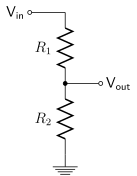
Credit: Wikipedia
You can use the resistor divider calculator to find the appropriate values for other voltages.
You should not use a voltage divider for high voltage differences as the current through the resistor can be excessive. You should also never connect the output of a voltage divider to yet another voltage divider.
Level shifter
A level shifter can be used to:
- Decrease voltage, such as 5V logic to 3.3V logic
- Increase voltage, such as 3.3V logic on the Particle device to a 5V sensor
- Bidirectional voltage translation, such as 3.3V I2C to 5V I2C
- Automatic direction sensing level sensing
Additional information will be provided in the future on options for level shifters.
TVS input protection
One common solution is to use a rail-to-rail TVS (transient voltage suppressor) with Zener diode to protect the input.
The examples here use a Diodes Inc. D1213A-02SOL-7 (TVS DIODE 3.3VWM 10VC SOT233). They're US$ 0.20 in single quantities and significantly less expensive in larger quantities. This version is in the SOT-23-3 package but there are variations in several common surface mount packages.
This chip isn't available in PTH packages for breadboards, but if you want to prototype a design in a breadboard, you can easily search for "SOT-23-3 breakout" and find items such as this one from Amazon which is 50 pieces for US$ 9.49. The SOT-23-3 is intended to be reflow soldered, but the pins are far enough apart that you can solder it by hand with a soldering iron fairly easily.
Example circuits
Voltage divider (5V)
One common situation is interfacing a 5V signal to 3.3V GPIO. A common solution, especially for analog signals, is a voltage divider:
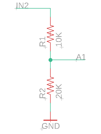
These resistors values do not exactly match 5 VDC to 3.3V (4095 on the ADC), but are close and use common off-the-shelf resistor values.
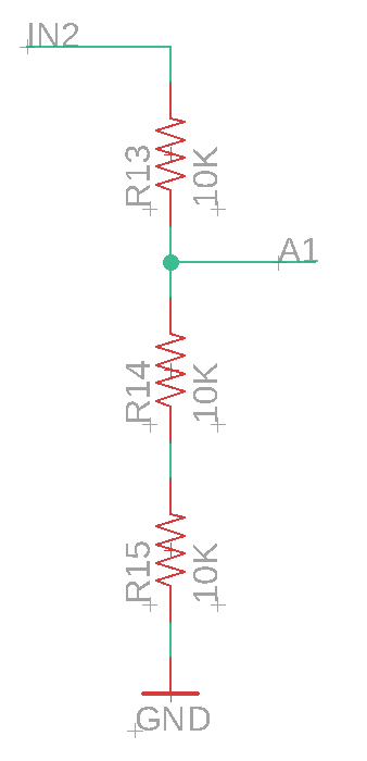
Because resistors in series add together, you could make this will three common 10K resistors, as well.
Voltage divider (12V)
This is a voltage divider for a 12 VDC signal, 27K on the high side, and 10K on the low side.
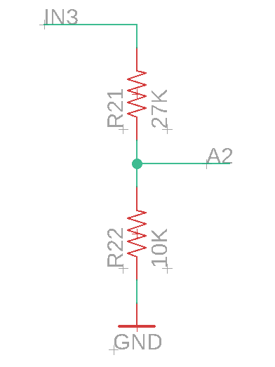
These resistors values do not exactly match 12 VDC to 3.3V (4095 on the ADC), but are close and use common off-the-shelf resistor values.
3.3V TVS
In the simplest case, a 3.3V analog or digital signal, you can use it like this:
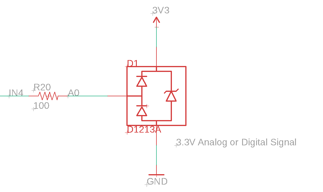
- The input signal is
IN4in this example. - It connects to
A0though any analog or digital input can be used. - The 100Ω resistor protects against excessive current through the diode.
- If the input voltage is negative, the diode shunts it to ground, protecting the MCU.
- If the input signal is slightly more than 3.3V, the diode shunts it to 3V3, protecting the MCU.
- If the input signal is very large, including ESD, the Zener diode stops the highest voltages, leaving the small differential to the rail-to-rail diodes.
5V TVS
You can also attach a voltage divider to the input of the TVS:
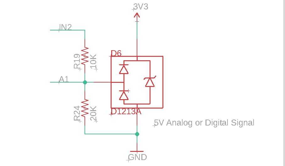
- The voltage divider works the same as Voltage divider (5V), above.
- Instead of the 100Ω R20 in 3.3V TVS, above, the high side of the voltage divider (R19) limits the input current.
Input design block
One technique that I like is to use this universal input block on my circuits. If I might want to change the voltage or other characteristics of the input in the future, I can just rework the board to change the resistors and not have to spin a new board.
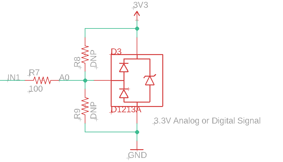
3.3V input block
This circuit is electrically the same as 3.3V TVS. The DNP, Do Not Populate, resistors are left off when assembling the board.
The layout on a circuit board looks like this:
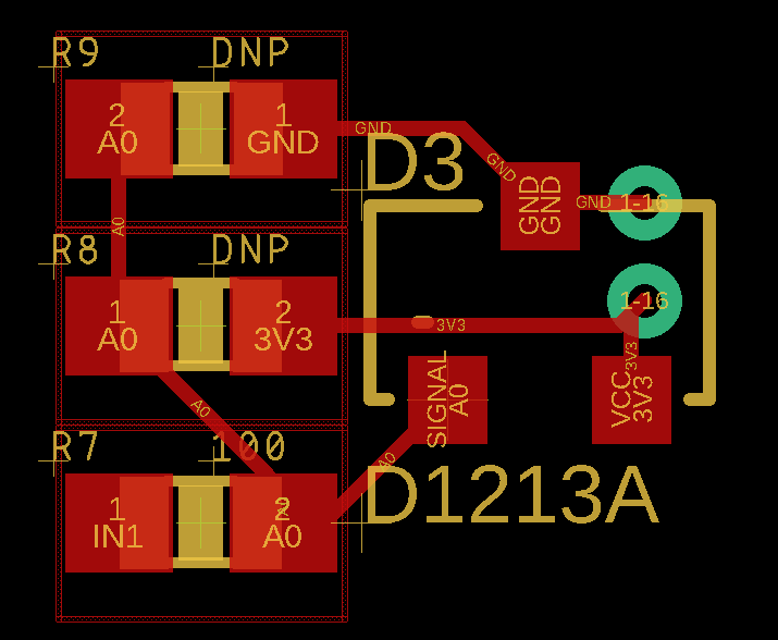
3.3V with pull-up input block
By adding R5, a 10KΩ resistor, the input now has a pull-up. If you are using an open-collector input (only pulls to ground), or you want the value to not float when disconnected, you can use a circuit like this.
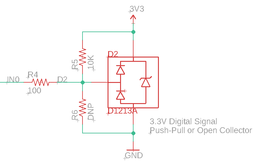
Of course you could make a pull-down by populating R6 instead of R5.
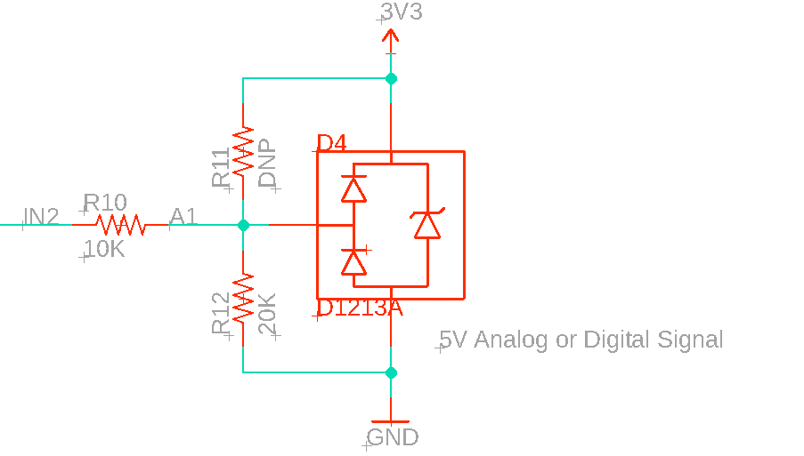
5V input block
This is the same design as Voltage divider (5V) with a 10K high-side and 20K low-side resistor.
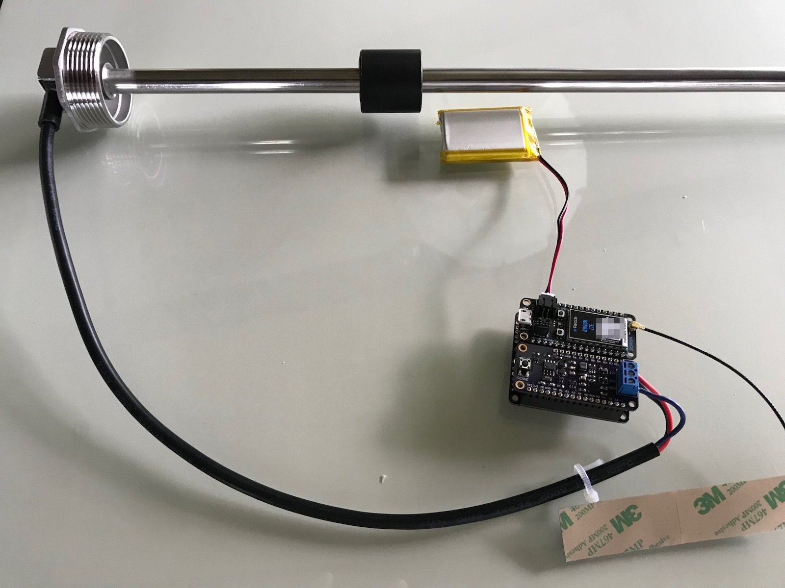
I used this input circuit with a tank level sensor, and it successfully protected my device. This magneto-resistive sensor is powered at 12V but supplies an analog output 0-5 VDC depending on level. While a voltage divider alone would be sufficient for this voltage, it also has the odd characteristics that if you have a loose ground wire, the output is around 8V! That would have been sufficient to damage the device if not for the protection diodes.
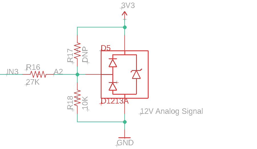
12V input block
This is the same design as Voltage divider (12V) with a 27K high-side and 10K low-side resistor.