
About serial
Learn about serial ports, UARTs, USB serial ports, RS-232, and more!
USB serial
The USB serial provides a way for the Photon/Electron to send data to the computer across the USB connection. Often this is used for debugging messages.
For example:
int counter = 0;

void setup() {
    Serial.begin(9600);
}

void loop() {
    Serial.printlnf("testing %d", ++counter);
    delay(1000);
}
The Serial.begin(9600); call initializes the serial port. When you're using the USB serial, the value doesn't actually matter. Sometimes you'll see Serial.begin(115200); but it really runs at the same fast speed regardless. In fact, you
can just omit the baud rate entirely and use Serial.begin().
The Serial.printlnf prints a formatted string to the debugging USB serial.
The documentation for Serial is here.
Particle CLI
A common way to view debug serial messages is the Particle CLI. Note that the CLI only reads serial messages, it is strictly a serial monitor, and you can't type things to the Photon/Electron. Still, it's quick and easy, and very handy.
$ particle serial monitor
Opening serial monitor for com port: "/dev/cu.usbmodemFD1161"
testing 1
testing 2
testing 3
testing 4
testing 5
testing 6
Particle Workbench
In Particle Workbench (VS Code), open the command palette (Command-Shift-P on the Mac, Ctrl-Shift-P on Windows and Linux) and select Particle: Serial Monitor.
Windows - using PuTTY or CoolTerm
For Windows, you can also use a program like PuTTY or CoolTerm.
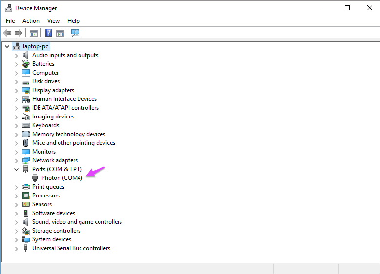
It's hard to say what COM port your Photon or Electron will use, but if you open the Windows Device Manager and expand Ports (COM & LPT) it should show the device.
This is the configuration screen for PuTTY:
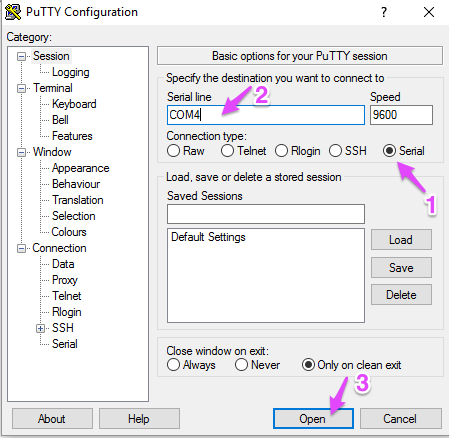
Click Serial (1) then enter the COM port number (2) then click Open (3).
Mac - using screen
Find the serial port that is being used using the Terminal program command line:
ls /dev/cu.usb*
It should return something like /dev/cu.usbmodemFD1161.
Then issue the command:
screen /dev/cu.usbmodemFD1161
Screen allows you you both send characters to the Photon or Electron as well as receive them from the USB serial device.
To close (kill) a screen session, press Ctrl-A then press k.
Linux - using screen
Find the serial port that is being used using the Terminal program command line:
ls /dev/ttyACM*
It should return something like /dev/ttyACM0.
Then issue the command:
screen /dev/ttyACM0
Screen allows you you both send characters to the Photon or Electron as well as receive them from the USB serial device.
To close (kill) a screen session, press Ctrl-A then press k.
Arduino IDE
Select the port from the Port hierarchical menu in the Tools menu.
Then select Serial Monitor from the Tools menu.
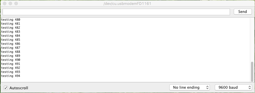
You can send data via serial with the Arduino IDE as well, but you need to enter text to send in the box at the top of the window and press Return or click Send.
Android phone or tablet with USB OTG
If your Android phone supports USB OTG ("on the go") and you have an OTG adapter cable, you may be able to use it for debugging serial! One caveat is that your phone probably won't power up a Photon, so this will probably only work if you have an external power source, like an Electron or Photon with a battery.
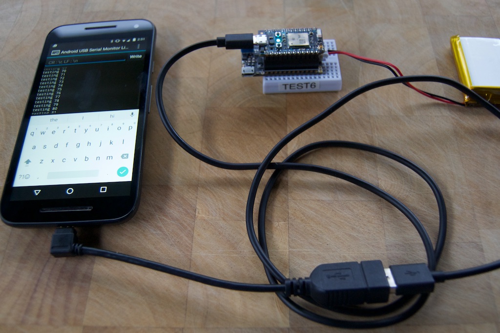
Install the "Android USB Serial Monitor Lite" application from the Google Play store.
Connect the device to your phone using a USB cable and a USB OTG adapter.
Open the serial monitor app and it should ask if you want to connect to the device. Tap yes and you should see a screen in the picture above.
Configuration using USB serial
If the Photon is in listening mode (blinking dark blue), configuration can also be done using the USB Serial port. Each of these commands only requires that you type the command letter (case-sensitive):
- i - Prints the device ID (24 character hexadecimal string)
- f - Firmware update (using ymodem)
- x - Exit listening mode
- s - Print system_module_info
- v - Device OS version
- L - Safe listen mode (does not run user code concurrently with listening mode)
- w - Configure Wi-Fi
- m - Print MAC Address for the Wi-Fi adapter
Listening mode is the default when you plug in a Photon the first time. You can also get into listening mode by holding down SETUP for about 3 seconds until the status LED blinks blue.
The commands other then the last two Wi-Fi related commands are also available on the Electron.
Changing operating modes with USB serial
Normally you press buttons to enter listening or DFU mode on the Photon or Electron. You can also trigger it by making a USB Serial connection at a specific baud rate.
For example, on the Mac you can use this command to enter DFU mode:
stty -f /dev/cu.usbmodemFD1141 14400
(The device name, cu.usbmodemFD1141 in this example, may be different on your computer.)
The special baud rates are:
- 14400 DFU mode (blinking yellow)
- 28800 Listening mode (blinking dark blue)
UART Serial
When connecting to an actual serial device, you'll be using one of the UART hardware serial ports. The Photon has one† and the Electron has three UART serial ports.
All of the devices have the Serial1 object, the main UART serial port, on the RX and TX pins.
- RX means serial data received into the device
- TX means serial data transmitted from the device
When you connect a Photon another device, say an Arduino, the RX pin on the Photon always gets connected to the TX pin of the Arduino and vice versa. This is always the case, even if you connect two Photons by serial.
† The Photon actually has two and the Electron four UART serial ports. The catch is that Serial2 is on the same pins as the RGB status LED. Using it requires soldering and disabling the status LED, which will make troubleshooting your device very difficult. It's a complicated enough topic that it has its own tutorial.
Additional ports on the Electron
The Electron has two additional UART serial ports that you can use, Serial4 and Serial5.
- C0 Serial5 RX
- C1 Serial5 TX
- C2 Serial4 RX
- C3 Serial4 TX
If you need Serial4 or Serial5 you'll need to enable the port by adding one or both of these includes near the top of your main source file:
#include "Serial4/Serial4.h"
#include "Serial5/Serial5.h"
Adding more UART ports
If you need more UART serial ports, you should use an I2C or SPI connected UART chip. It is not possible to use a USB serial adapter connected to the Particle device USB port.
The SC16IS740 and SC16IS750 work well with all Particle devices. The SC16IS740RK library works well on both Gen 2 and Gen 3 devices and the instructions can be found at that link.
Searching for SC16IS750 will find a number of results for inexpensive breakout boards on Amazon, eBay, or AliExpress.
Serial logic levels
The Photon and Electron are 3.3V serial devices that are 5V tolerant. When transmitting data, logic 1 values are 3.3V and logic 0 values are 0V, so we list the port as being 3.3V.
Many 5V serial devices will correctly respond to 3.3V values as logic 1 even though it is out-of-spec. Likewise, the Photon doesn't mind having 5V levels for logic 1 on the RX pins. So you often can connect a Photon directly to a 5V serial device, like an Arduino. This is often referred to as "TTL serial" as it uses the 5V logic levels used by TTL (transistor-transistor logic) devices.
One thing that you absolutely must never do is connect a Photon directly to a computer or other device using an actual RS232 interface. A converter is required and is described in the next section.
Gen 3 devices including the Argon, Boron, and B-Series SoM are not 5V tolerant and can only use 3.3V serial logic levels.
Interfacing to RS232 devices
Actual RS232 devices, such as old computers, newer computers with an adapter, and various external hardware devices likely use "real" RS232 signal levels, which can range between +15V and -15V. This will cause immediate, permanent damage to the Photon or Electron if connected directly.
A TTL serial to RS232 adapter board is typically used in these cases. They are available from places like SparkFun. You can also find them on eBay, search for "TTL RS232 breakout".
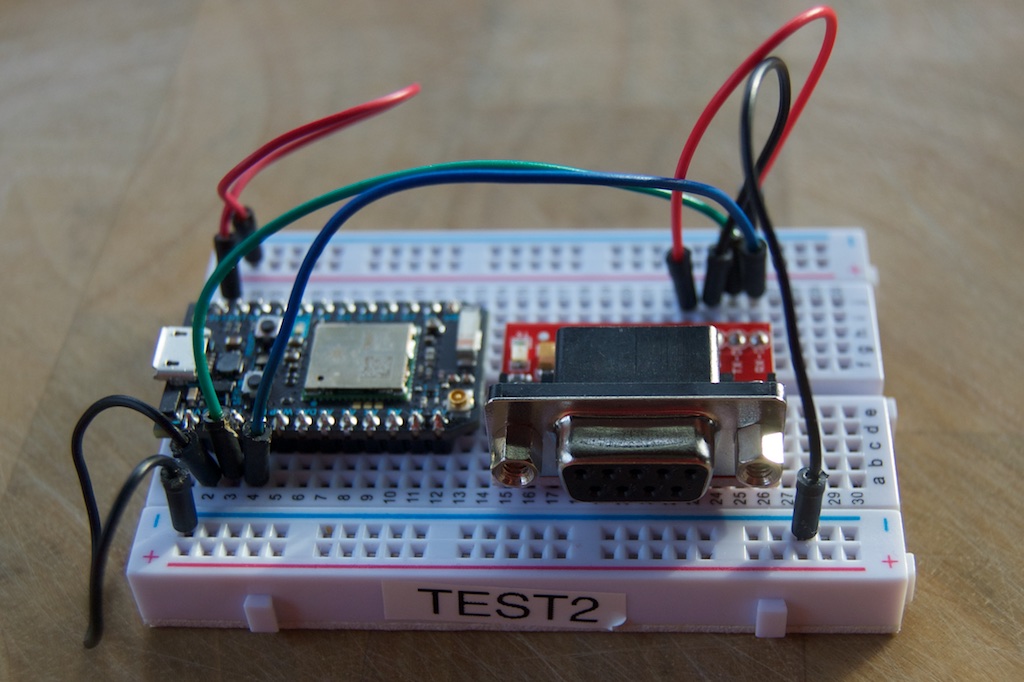
Make the following connections:
- Converter VCC to Photon 3V3 (red)
- Converter GND to Photon GND (black)
- Converter TX-O to Photon TX (green)
- Converter TX-I to Photon RX (blue)
Note that TX and RX don't cross here, between the Photon and the converter, because they're crossed in the RS232 serial cable DCE to DTE connection.
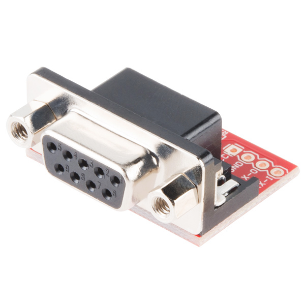
Connectors
Two different connectors are used for RS232 serial, the DB9 and the DB25. The DB25, a "D" shaped 25-pin connector was the original connector but IBM PC compatible computers mostly settled on the smaller DB9 connector. The DB9 is also referred to as a DE9 connector.
This is a close-up of the DB9 female connector on the SparkFun converter board.
DTE/DCE
Serial devices are either DTE (data terminal equipment) or DCE (data communication equipment). These names come from the early days of dumb terminals (DTE) connected to modems (DCE). It doesn't entirely matter which device is which, but if you have to connect two like items (say DTE to DTE) you need a null modem adapter that crosses the TX and RX lines (among others).
Typically DTE devices have a male connector. Pin 2 is an input and pin 3 is an output.
Likewise, DCE devices typically have a female connector. Pin 2 is an output and pin 3 is an input.
The SparkFun board has a female DB9 and makes the Photon a DCE. This makes sense because most computer serial ports are DTE.
Baud rate, bits, parity, and stop bits (Gen 2)
There are four configuration parameters for serial, and you must make sure they're all set correctly, otherwise communication will often fail, either with no data or garbage characters received.
The baud rate is the speed that data is sent. A common value is 9600. The valid values for the Photon, P1 and Electron are 1200, 2400, 4800, 9600, 14400, 19200, 28800, 38400, 57600, and 115200. Neither device can use speeds under 1200 (such as 300 or 600).
The number of bits per byte is typically 8. It's occasionally 7 or 9. There is limited support for 9 bit in Device OS version 0.5.0 and later, and full support for 7 and 9 bit in 0.6.0 and later.
The parity is a method of detecting errors in the data. It can be none ("N"), odd ("O") or even ("E"). Support for parity is included in 0.5.0 and later.
The number of stop bits is 1 or 2. Support for stop bit setting is included in 0.5.0 and later.
The last three things are typically combined into a single string, for example "8N1" means 8 bits, no parity, 1 stop bit. "7E1" means 7 bits, even parity, 1 stop bit. And so on.
The available values are:
- SERIAL_7E1
- SERIAL_7E2
- SERIAL_7O1
- SERIAL_7O2
- SERIAL_8N1
- SERIAL_8N2
- SERIAL_8E1
- SERIAL_8E2
- SERIAL_8O1
- SERIAL_8O2
- SERIAL_9N1
- SERIAL_9N2
You use these with the Serial.begin call, for example:
Serial1.begin(9600, SERIAL_9N1);
Baud rate, bits, parity, and stop bits (Gen 3)
On the Argon, Boron, and B-Series SoM, the available baud rates are: 1200, 2400, 4800, 9600, 19200, 28800, 38400, 57600, 76800, 115200, 230400, 250000, 460800, 921600 and 1000000
They also only support 8 bits, 1 stop bit, and either none or even parity. No other modes are supported.
- SERIAL_8N1 - 8 data bits, no parity, 1 stop bit (default)
- SERIAL_8E1 - 8 data bits, even parity, 1 stop bit
You use these with the Serial.begin call, for example:
Serial1.begin(9600);
Flow control
There are two types of flow control in serial: hardware (RTS/CTS) and software (XON/XOFF).
The Photon and Electron only support hardware flow control on Serial2, which requires disabling the RGB LED. Flow control pins are A7(CTS) and RGB-R(RTS).
On the Argon, Boron, and B-Series SoM hardware flow control is available on Serial1 on pins D3(CTS) and D2(RTS).
SERIAL_FLOW_CONTROL_NONE- no flow controlSERIAL_FLOW_CONTROL_RTS- RTS flow controlSERIAL_FLOW_CONTROL_CTS- CTS flow controlSERIAL_FLOW_CONTROL_RTS_CTS- RTS/CTS flow control
Serial1.begin(9600, SERIAL_FLOW_CONTROL_RTS_CTS);
None of the devices support software (XON/XOFF) flow control. In some limited cases, you could note when you receive XOFF (Ctrl-S) in your received data and stop sending, however there is currently no way to stop the send FIFO from sending, so this will only work when you don't have any data waiting to be sent.
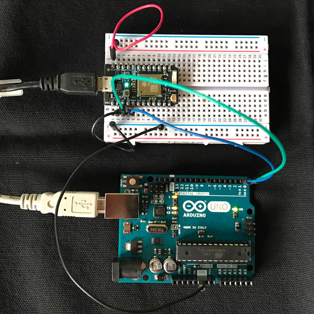
Communicating with an Arduino
Here's an example of using serial to communicate between an Arduino (Uno, in this case) and a Photon.
- Photon TX connects to Arduino RX (0) (green wire)
- Photon RX connects to Arduino RX (1) (blue wire)
- Photon GND connects to Arduino GND (black wire)
Remember: RX and TX always cross, and you must have a common GND connection.
This is a rather silly example: Every 2 seconds the Photon sends a number to the Arduino by UART serial. The Arduino parses this number, increments it, and sends it back. The Photon prints it out via the debugging serial.
Remember that serial is a byte-oriented protocol, so we keep reading bytes until we find a character that marks the end of the transmission. I selected the new line character ("\n").
Arduino code:
// Constants
const size_t READ_BUF_SIZE = 64;

// Forward declarations
void processBuffer();

// Global variables
char readBuf[READ_BUF_SIZE];
size_t readBufOffset = 0;

void setup() {
  // Serial TX (1) is connected to Photon RX
  // Serial RX (0) is connected to Photon TX
  // Ardiuno GND is connected to Photon GND
  Serial.begin(9600);
}

void loop() {
  // Read data from serial
  while(Serial.available()) {
    if (readBufOffset < READ_BUF_SIZE) {
      char c = Serial.read();
      if (c != '\n') {
        // Add character to buffer
        readBuf[readBufOffset++] = c;
      }
      else {
        // End of line character found, process line
        readBuf[readBufOffset] = 0;
        processBuffer();
        readBufOffset = 0;
      }
    }
    else {
      readBufOffset = 0;
    }
  }

}

void processBuffer() {
  int receivedValue = atoi(readBuf);

  // This program just increments the value sent by the Photon and returns it
  Serial.print(receivedValue + 1, DEC);
  Serial.print('\n');
}
Photon code:
#include "Particle.h"

// Constants
const unsigned long SEND_INTERVAL_MS = 2000;
const size_t READ_BUF_SIZE = 64;

// Forward declarations
void processBuffer();

// Global variables
int counter = 0;
unsigned long lastSend = 0;

char readBuf[READ_BUF_SIZE];
size_t readBufOffset = 0;

void setup() {
    Serial.begin(9600);

    // Serial1 RX is connected to Arduino TX (1)
    // Serial2 TX is connected to Arduino RX (0)
    // Photon GND is connected to Arduino GND
    Serial1.begin(9600);
}

void loop() {
    if (millis() - lastSend >= SEND_INTERVAL_MS) {
        lastSend = millis();

        Serial1.printlnf("%d", ++counter);
        Serial.printlnf("Sent to Arduiuno: %d", counter);
    }

    // Read data from serial
    while(Serial1.available()) {
        if (readBufOffset < READ_BUF_SIZE) {
            char c = Serial1.read();
            if (c != '\n') {
                // Add character to buffer
                readBuf[readBufOffset++] = c;
            }
            else {
                // End of line character found, process line
                readBuf[readBufOffset] = 0;
                processBuffer();
                readBufOffset = 0;
            }
        }
        else {
            Serial.println("readBuf overflow, emptying buffer");
            readBufOffset = 0;
        }
    }

}

void processBuffer() {
    Serial.printlnf("Received from Arduino: %s", readBuf);
}
Sample output:
$ particle serial monitor
Opening serial monitor for com port: "/dev/cu.usbmodemFD1161"
Sent to Arduiuno: 1
Received from Arduino: 2
Sent to Arduiuno: 2
Received from Arduino: 3
Sent to Arduiuno: 3
Received from Arduino: 4
Sent to Arduiuno: 4
Received from Arduino: 5
There's also another example sending multiple pieces of data from the Arduino to the Photon.
More code tips
Some additional helpful tips:
Process all available characters
You should process all available serial characters in each call to loop. In other words, don't do this, using an if statement. Use a while, instead.
void setup() {
    Serial.begin(9600);
    Serial1.begin(9600);
}

void loop() {
    // Don't do this! Use a while loop instead of an if to make sure all
    // of the data is processed in each call to loop
    if (Serial1.available()) {
        Serial.write(Serial1.read());
    }
}
The reason is that loop may be called at most 1000 times per second, and often fewer, so it's possible to fall behind faster serial speeds unless you handle all of the outstanding bytes at once.
Avoid delay in loop
When processing serial data, make sure you don't block the loop. One obvious way to do this is using delay, but there are other more subtle ways.
For example, if you wanted to do something once per second while handling serial data, you should not do this:
#include "Particle.h"

void setup() {
    Serial.begin(9600);
    Serial1.begin(9600);
}

void loop() {
    while (Serial1.available()) {
        Serial.write(Serial1.read());
    }

    // Don't do this!
    delay(1000);
    Serial.println("called once per second");
}
The problem is that serial data won't be handled during the 1 second long delay, which could cause data to be lost.
Instead you could do this:
unsigned long lastTime = 0;

void setup() {
    Serial.begin(9600);
    Serial1.begin(9600);
}

void loop() {
    while (Serial1.available()) {
        Serial.write(Serial1.read());
    }

    if (millis() - lastTime >= 1000) {
        lastTime = millis();
        Serial.println("called once per second");
    }
}
This allows loop to run freely, and still only execute some code once per second.
Reading lines of data
Serial is a byte or character-oriented method for transferring data. The hardware assures that you will always receive a character at a time; you'll never get half a character, for example.
For convenience, data may be grouped into lines of characters. The Arduino example, above, read a line at a time. Even if you're expecting a line of data, there is no guaranteed that all of your data will arrive at once. In fact, it's quite likely that it won't and you will have to write your code to handle that.
One easy way to do this is to use readStringUntil. For example:
void setup() {
    Serial.begin(9600);

    // Wait up to 10 seconds for a line to arrive
    Serial.setTimeout(10000);
}

void loop() {
    String s = Serial.readStringUntil('\n');
    Serial.printlnf("got %s", s.c_str());
}
This is great only if you have nothing to else to do in your loop. The call may block for up to 10 seconds (as configured here), which may be unacceptable for some applications. In that case, you may prefer to do this manually, so the loop runs freely:
// Constants
const size_t READ_BUF_SIZE = 64;
const unsigned long CHAR_TIMEOUT = 10000;

// Global variables
char readBuf[READ_BUF_SIZE];
size_t readBufOffset = 0;
unsigned long lastCharTime = 0;

void setup() {
    Serial.begin(9600);
}

void loop() {
    // Read data from serial
    while(Serial.available()) {
        if (readBufOffset < READ_BUF_SIZE) {
            char c = Serial.read();
            if (c != '\n') {
                // Add character to buffer
                readBuf[readBufOffset++] = c;
                lastCharTime = millis();
            }
            else {
                // End of line character found, process line
                readBuf[readBufOffset] = 0;
                Serial.printlnf("got: %s", readBuf);
                readBufOffset = 0;
            }
        }
        else {
            Serial.println("readBuf overflow, emptying buffer");
            readBufOffset = 0;
        }
    }
    if (millis() - lastCharTime >= CHAR_TIMEOUT) {
        lastCharTime = millis();
        readBuf[readBufOffset] = 0;
        Serial.printlnf("got timeout: %s", readBuf);
        readBufOffset = 0;
    }
}
Waiting at startup for USB serial connection
If you want to wait in setup for the USB serial to connect so you can make sure you can see debugging messages, you can add something like this:
void setup() {
  Serial.begin();

  // Wait for a USB serial connection for up to 10 seconds
  waitFor(Serial.isConnected, 10000);
}
If you are porting code from Arduino, sometimes you will see the following code. This is intended to
wait for serial to be connected to by USB, but it does not work that way on Particle devices and you
should instead use the waitFor method above.
void setup() {
  Serial.begin(9600);

  while(!Serial); // Do not do this
}