
Beyond prototyping
Going from solderless breadboards to SMD components across Particle devices
Solderless breadboards 1
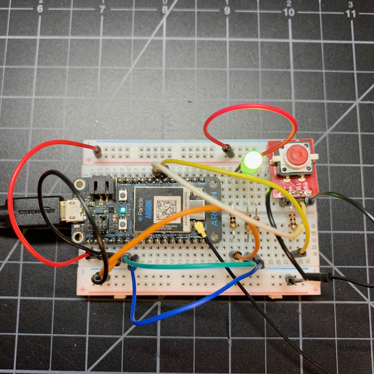
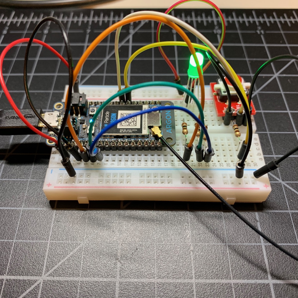
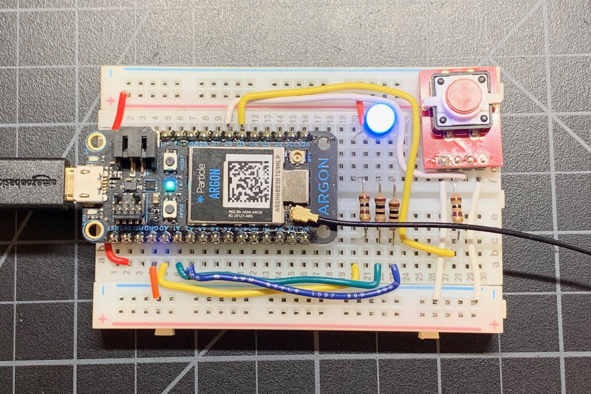
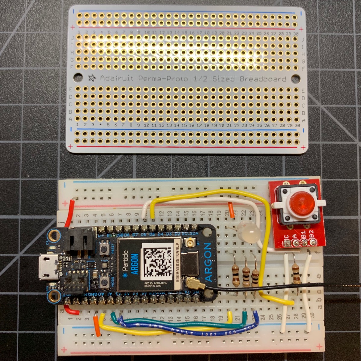
One of the most common ways to start building your project is to use a solderless breadboard. Here's my switch demo circuit in pure prototyping mode. There's an RGB LED and an LED button to the right of the Argon. This version uses long flexible wires, which are easy to set up and are easily reusable.
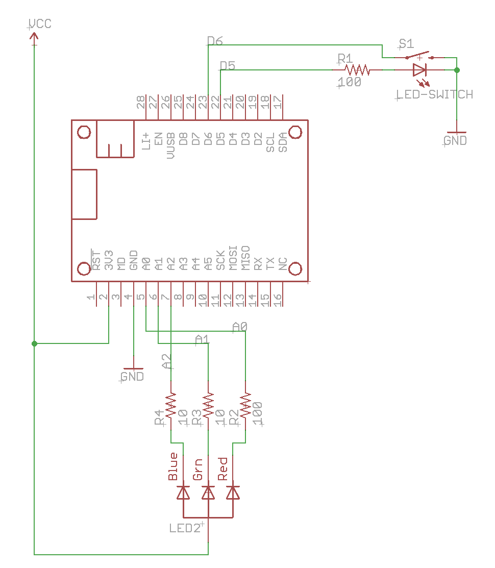
This is the schematic for the circuit:
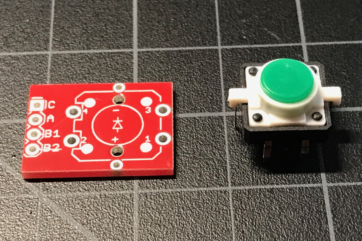
Because the LED button switch pins don't line up with the holes on a solderless breadboard (0.1"), there's a small adapter board.
Bill of Materials (BOM)
| Quan | Item | Example | Price |
|---|---|---|---|
| 1 | LED tactile button | SparkFun | $2.10 |
| 1 | Button adapter | SparkFun | $1.50 |
| 1 | RGB LED | SparkFun | $2.05 |
| 2 | 10 ohm resistor | ||
| 2 | 100 ohm resistor |
Solderless breadboards 2
One way to dress up your project is to switch to solid wires. It's a bit more work, but it certainly looks more professional and is good for projects you want to keep as-is.
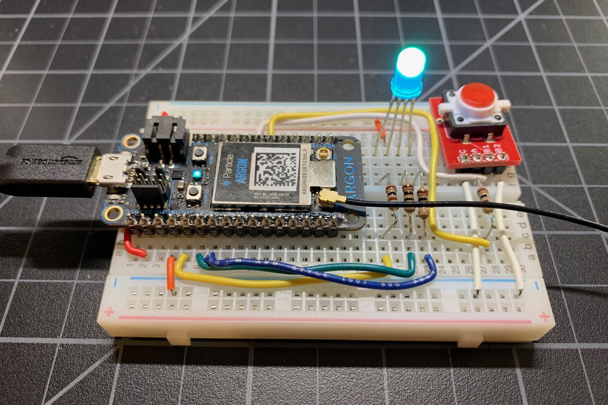
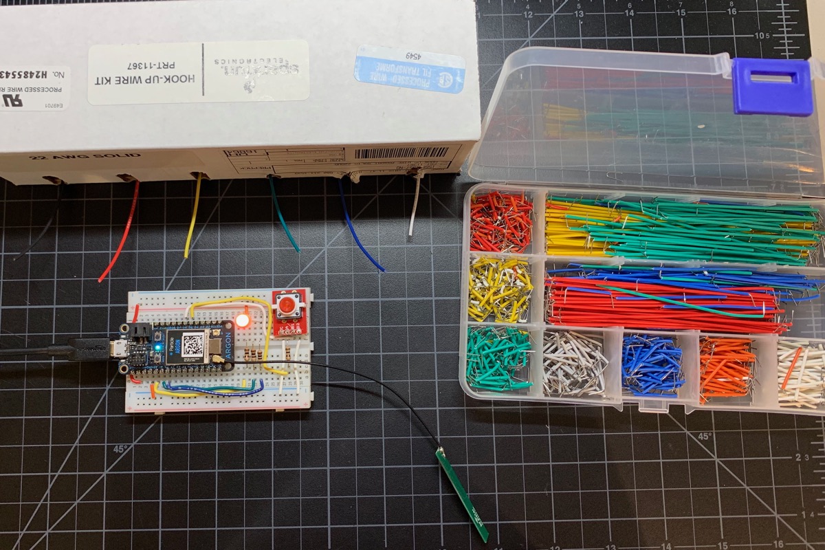
I used a combination of pre-formed wires and wires I cut, stripped, and bent to length from a SparkFun hookup wire kit.
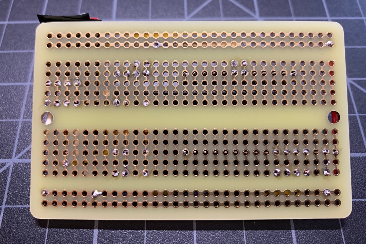
Perma-Proto
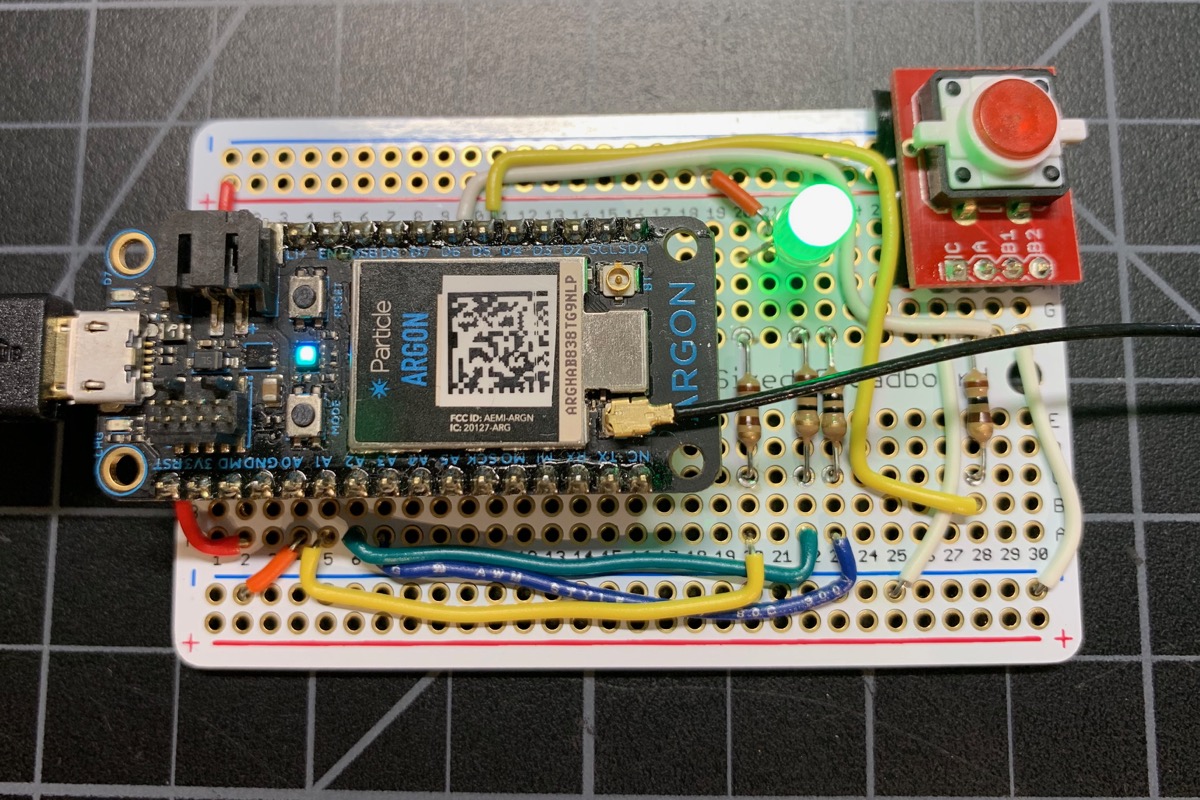
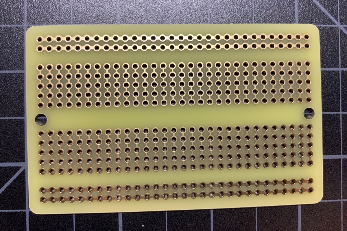
Once you've built and tested your solderless breadboard with solid wires, the next step up is an Adafruit Perma-Proto board. It has the same wiring as a solderless breadboard, but you solder the wires in place.
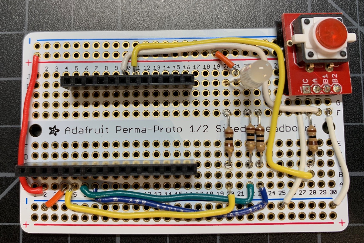
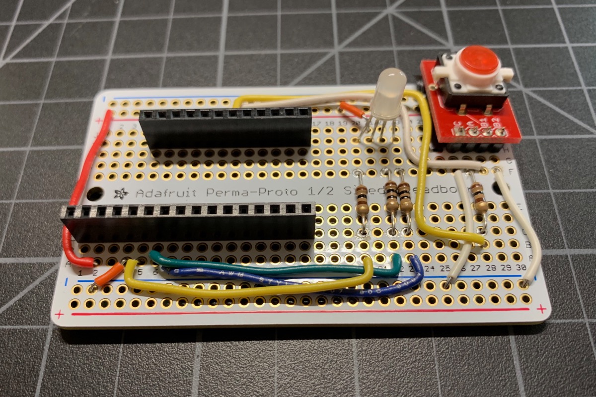
Resist the temptation to solder your device in place. Always use sockets, otherwise it's really a pain to troubleshoot or swap out the device if a problem occurs.
Note that you should use these headers or ones like them. The spacing between rows is not the same as most IC sockets. Plus, the pins on Particle devices are square, not the flat like IC chip leads, and wouldn't fit securely in an IC socket.
All you need to do is transfer over the component and wires and solder them to the board!
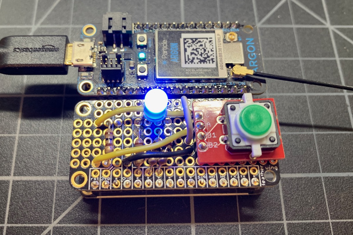
Feather prototyping board
One of the nice features of the Gen 3 prototyping devices is the use of the Adafruit Feather form-factor. Not only does this allow the devices to be easily swapped, but there are a large number of accessories like displays, GPS modules, and sensors already built in the Feather form-factor. Using a doubler, tripler, or quadrupler, you can add these to your project with no loose wires and no soldering!
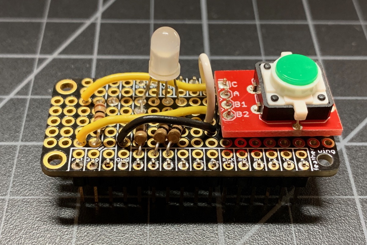
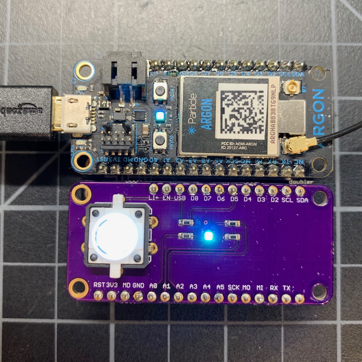
However, sometimes you want something a little more custom. In this version, instead of using a big perma-proto board, I used a little FeatherWing solder prototype board. This is one in a Feather Doubler with an Argon:
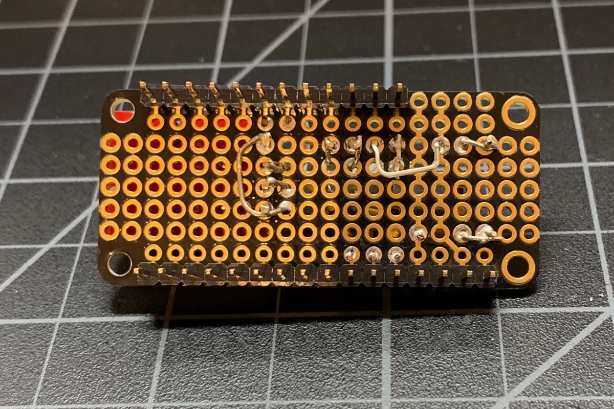
And the board itself:
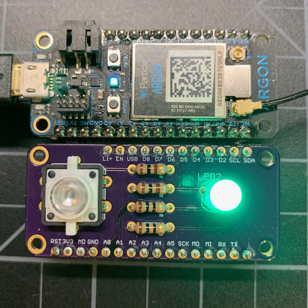
Feather PTH board (through-hole components)
While the previous soldered boards all work fine, you can really make things look professional with a custom printed circuit board. This one uses hand-soldered through-hole components. It's referred to a PTH, plated through-hole.
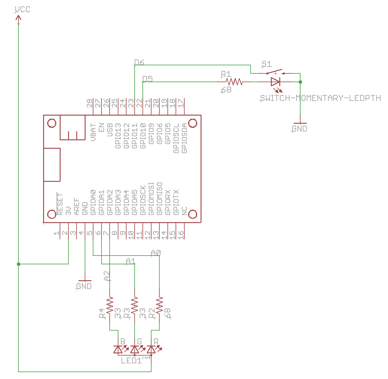
I created the board schematic in Eagle CAD. This small two-layer board can be done in the free version of Eagle CAD.
The Eagle CAD schematic and board files are in the eagle directory in the GitHub repository.
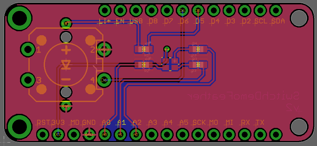
The other part is creating the board file, which includes the actual placement of the components and the traces, which take the place of the wires. Here's by board file in Eagle.
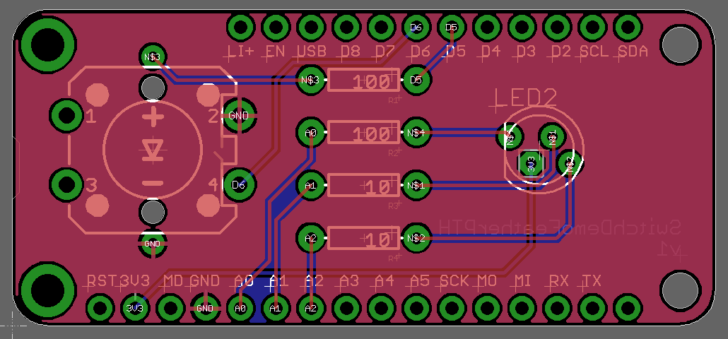
I ordered these board from OshPark.
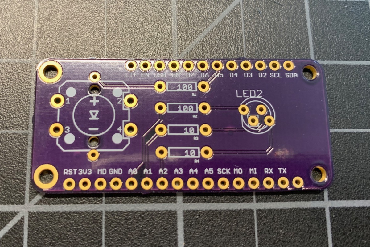
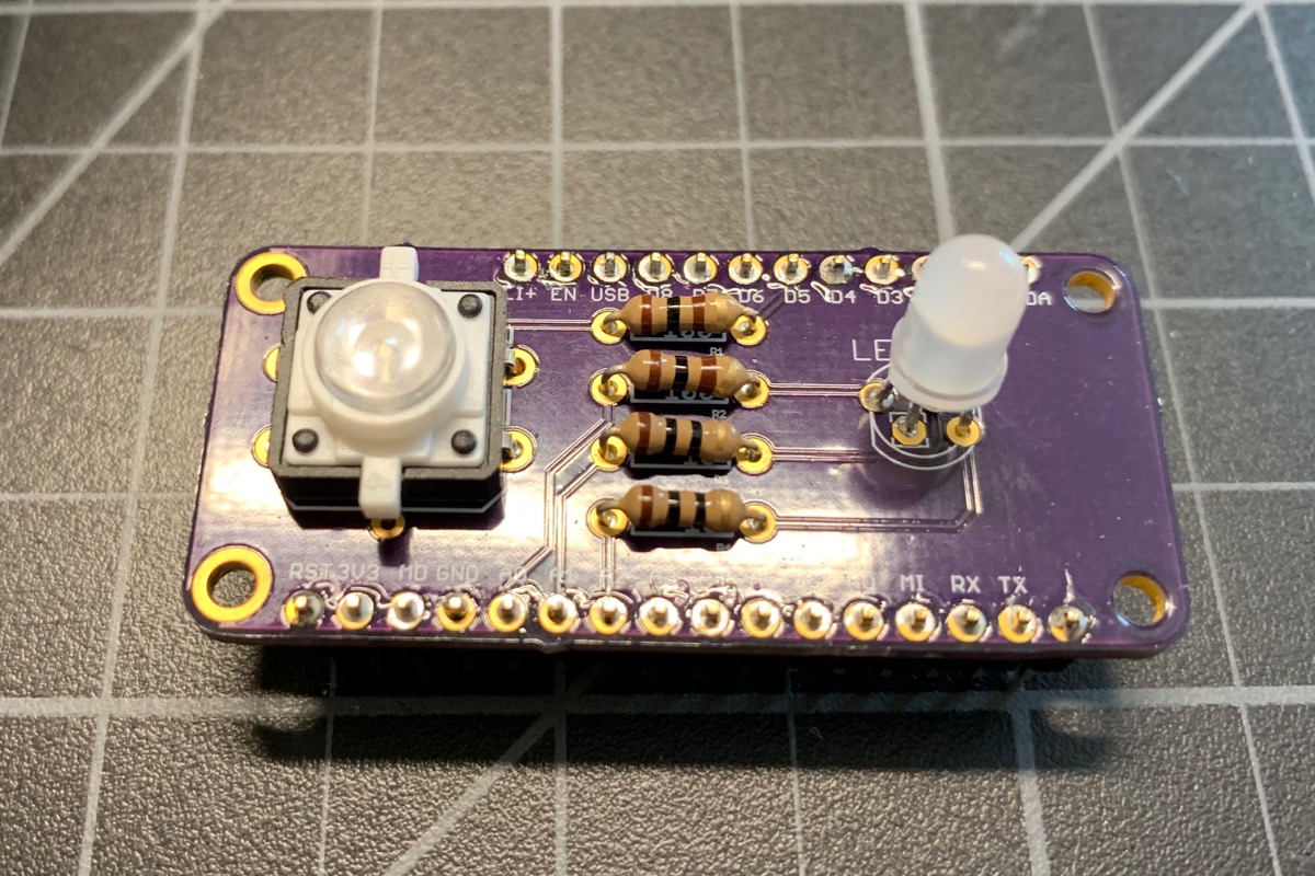
Here are the components soldered in place. It's way faster to solder the components onto a circuit board than mess with all of the individual wires. And it looks so neat and clean!
Feather SMD components board
The next step up is to switch to use SMD (surface mount device) components. The switch button is still through-hole soldered, but the resistors and LED are SMD.
As your designs get more complex, being able to use smaller SMD components saves space and is actually easier than hand soldering once you get the hang of it. Also, many modern ICs are only available in SMD form-factor. The SMD RGB LED in this design is significantly less expensive than the PTH LED used above ($0.19 vs. $2.05).
The SMD LED uses different current-limiting resistors but the schematic is otherwise the same.
In order to assemble a SMD board, you'll use solder paste. I like this kind in a little syringe. This is low-temperature solder paste, which is easy to work with and is lead-free.
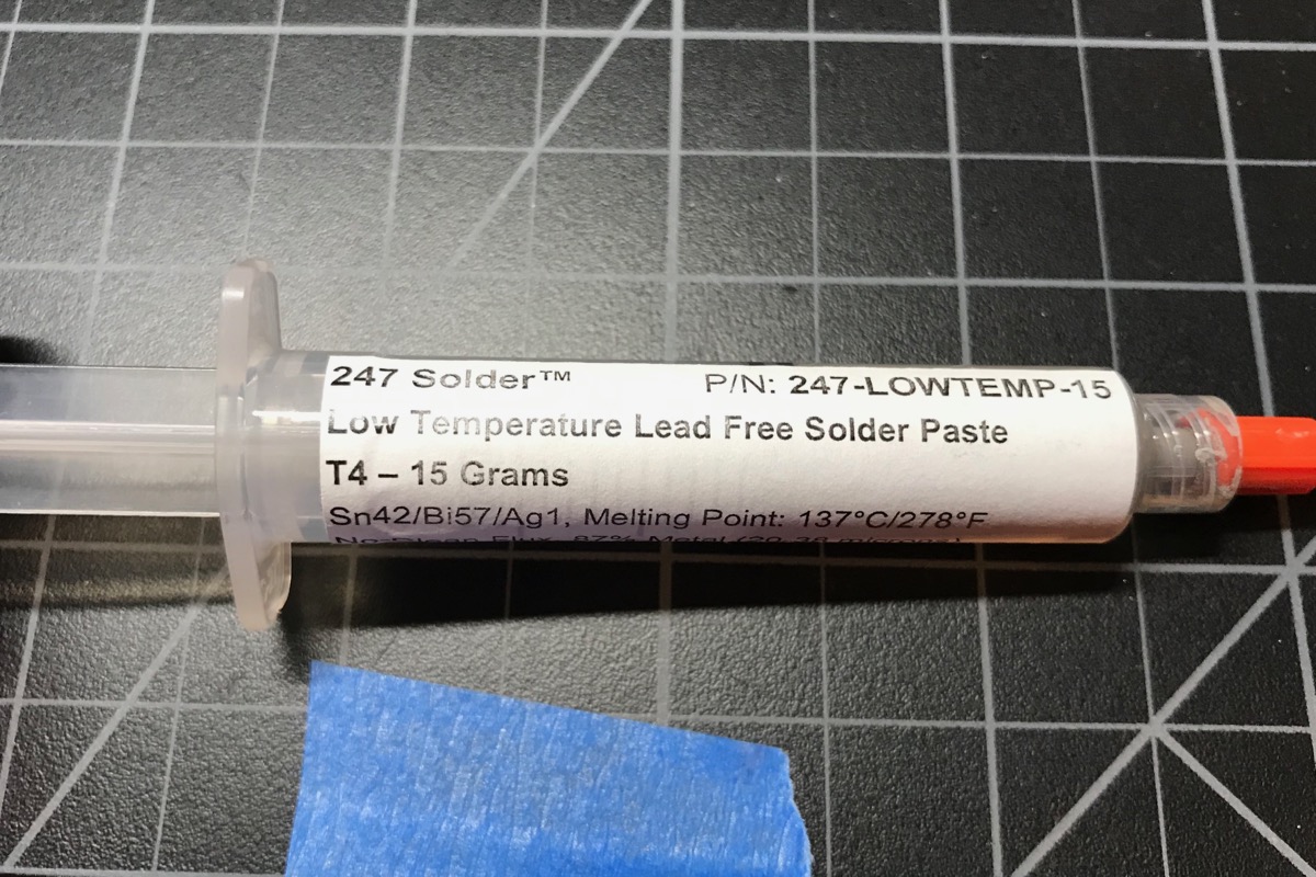
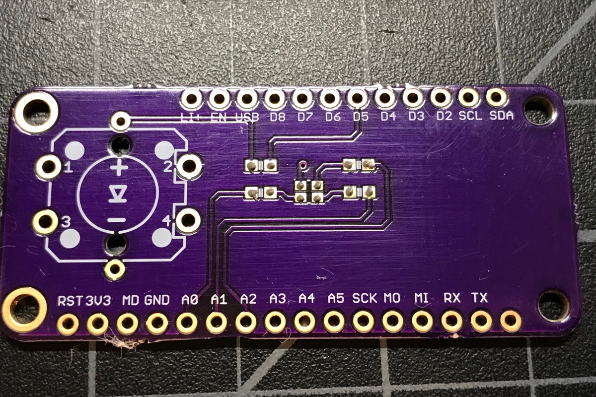
Like the previous board, I ordered it from OshPark. Using the small syringe tip I put a little dot of solder on all of the SMD pads.
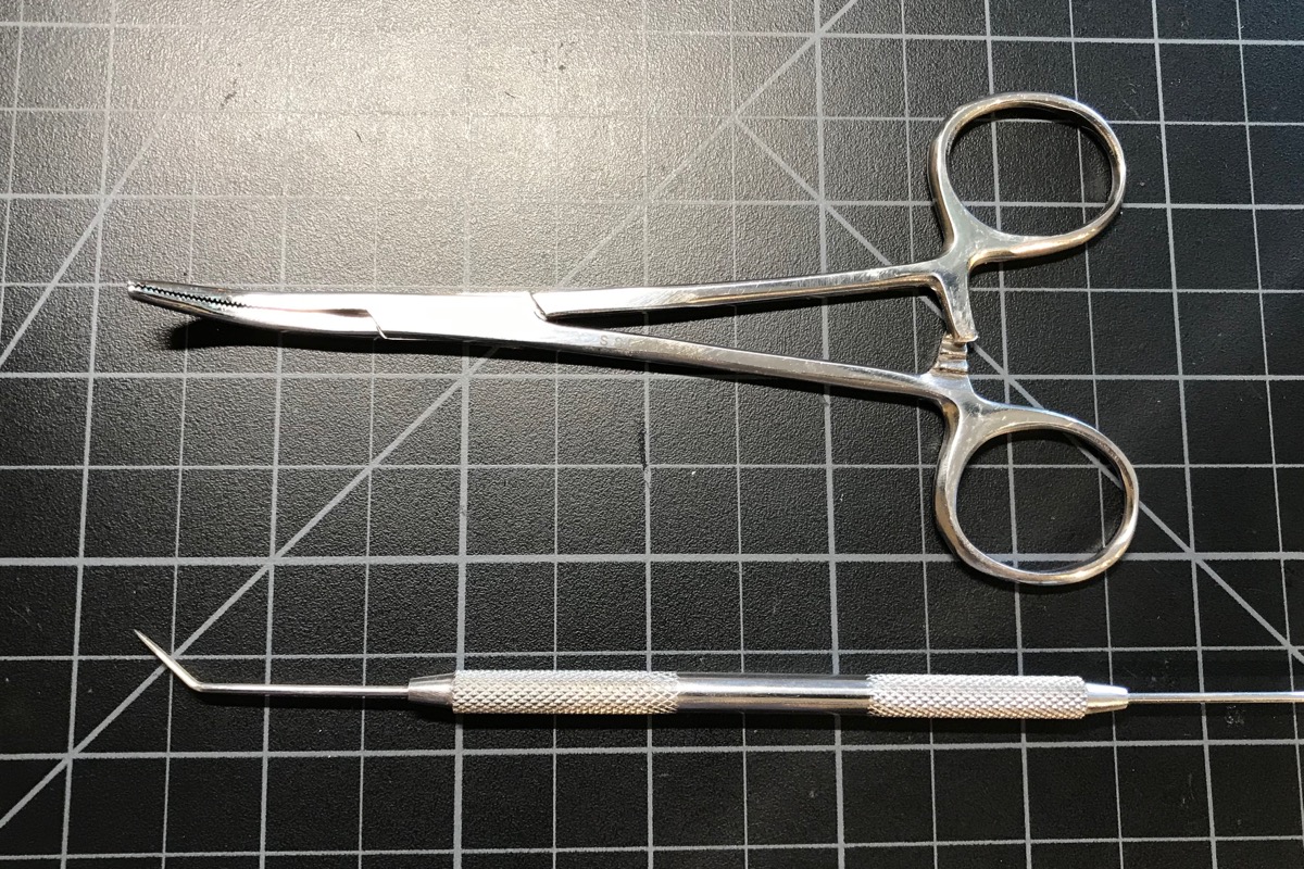
The next step is to place the components on the board. I like to use forceps and a dental pick. Some people prefer tweezers.
The the board goes into the reflow oven. This is an inexpensive T-962 which works fine for simple boards.
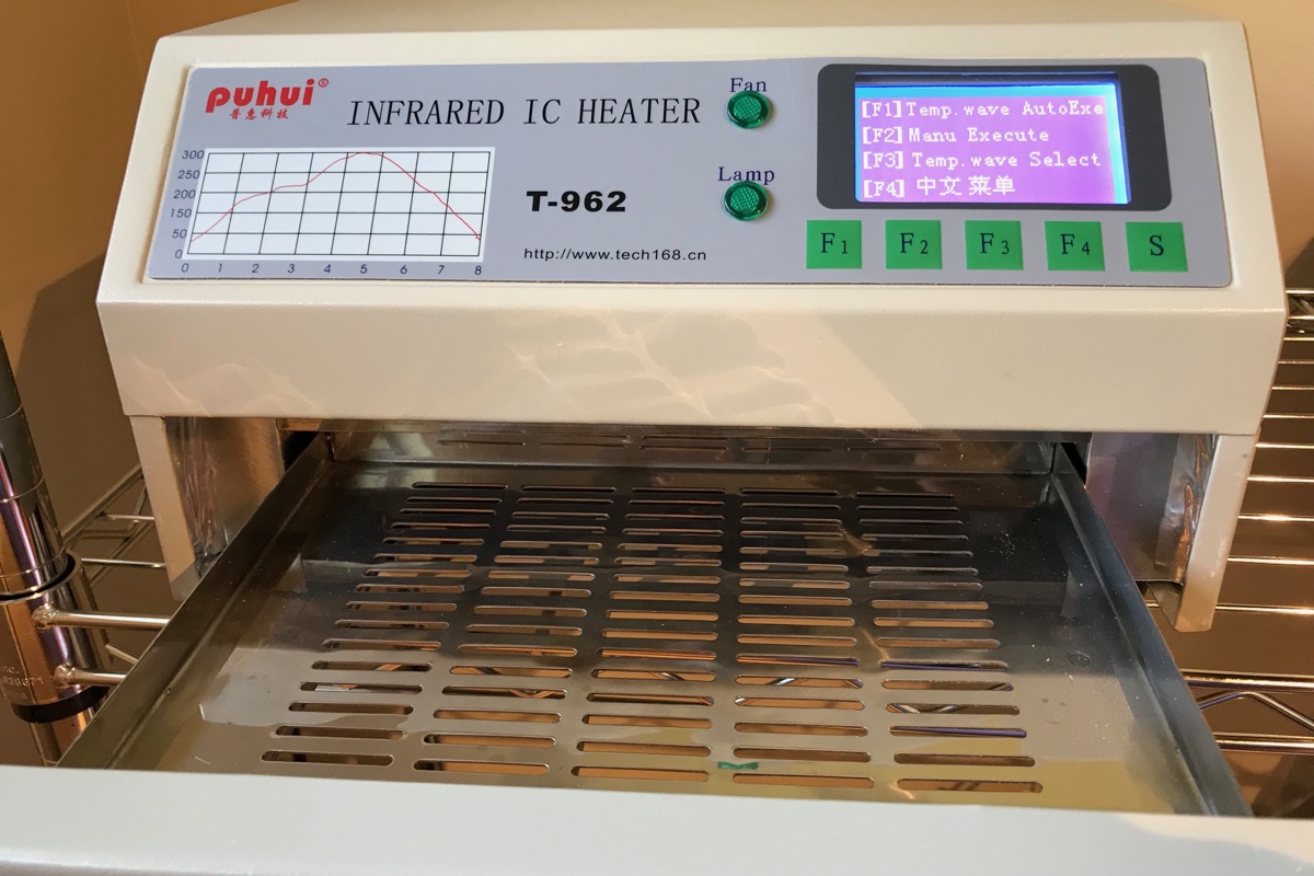
There are a number of DIY techniques including using a skillet or baking them in a toaster oven, but using a real reflow oven is more accurate.
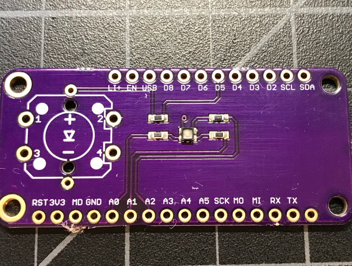
And here's the board after reflow soldering:
The Eagle CAD schematic and board files are in the eagle directory in the GitHub repository.
Bill of Materials (BOM)
| Quan | Item | Example | Price |
|---|---|---|---|
| 1 | LED tactile button | SparkFun | $2.10 |
| 1 | RGB LED | Cree CLMVC-FKA-CL1D1L71BB7C3C3 | $0.19 |
| Male Header Pins | Sullins PRPC040SAAN-RC | ||
| 2 | 33 ohm resistor 0603 | Panasonic | |
| 2 | 68 ohm resistor 0603 | Panasonic |
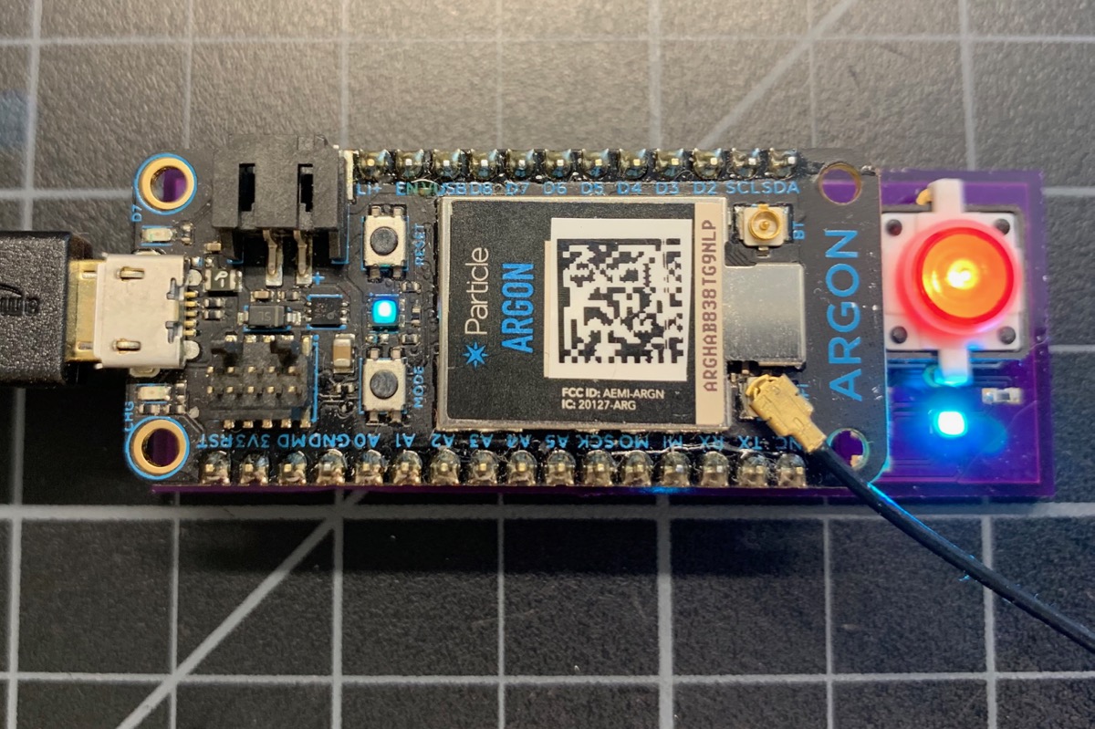
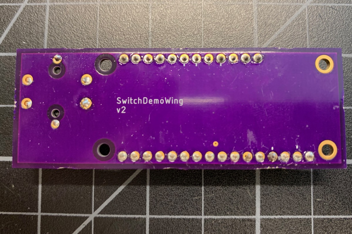
Wing under-mount board
You don't need to make your boards into the actual FeatherWing form-factor. You can make an under-mount board as well. This is handy for larger designs.
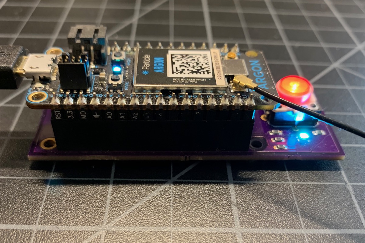
The schematic is the same, but the Eagle board layout is different:
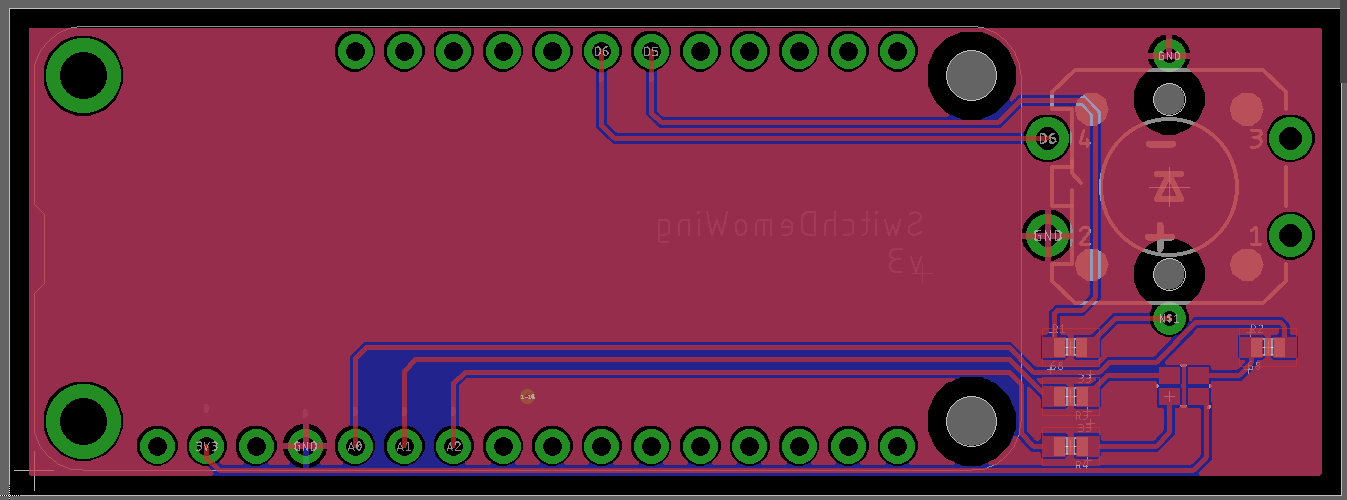
The Eagle CAD schematic and board files are in the eagle directory in the GitHub repository.
Bill of materials (bom)
| Quan | Item | Example | Price |
|---|---|---|---|
| 1 | LED tactile button | SparkFun | $2.10 |
| 1 | RGB LED | Cree CLMVC-FKA-CL1D1L71BB7C3C3 | $0.19 |
| 1 | 12-pin header | Sullins | $0.78 |
| 1 | 16-pin header | Sullins | $0.98 |
| 2 | 33 ohm resistor 0603 | Panasonic | |
| 2 | 68 ohm resistor 0603 | Panasonic |
Photon (Gen 2 Wi-Fi)
The Photon board is a lot like the under-mount FeatherWing board, but it has two 12-pin headers to fit a Photon.
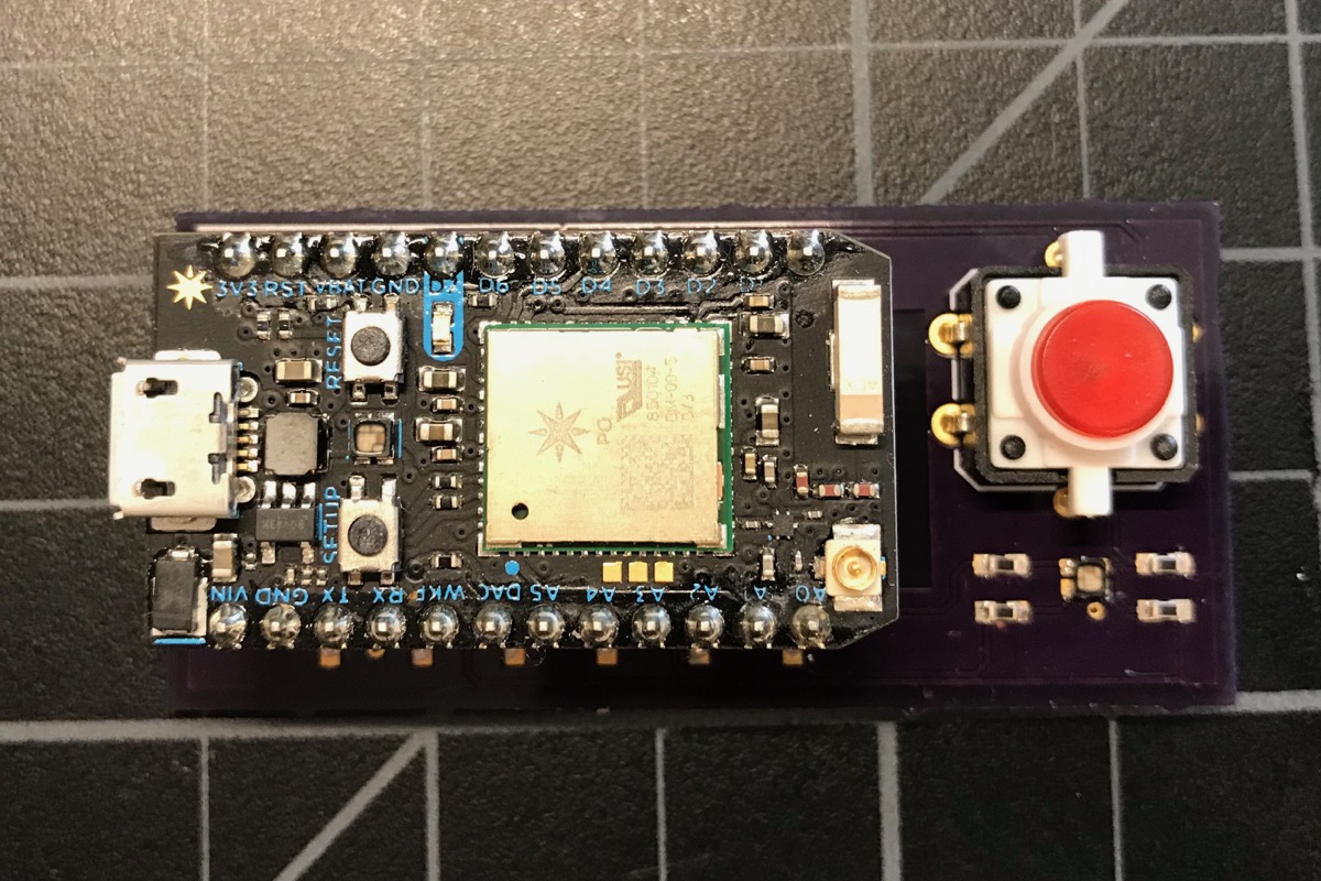
The Gen 2 devices (Photon, P1, Electron, and E-Series) use different pins because the STM32F205 processor supports PWM for the RGB LED on different pins. Thus the schematic is slightly different:
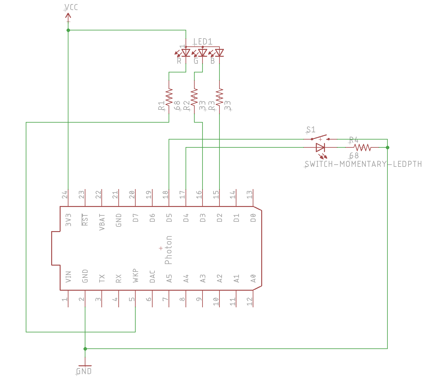
The Eagle CAD schematic and board files are in the eagle directory in the GitHub repository.
Bill of Materials (BOM)
| Quan | Item | Example | Price |
|---|---|---|---|
| 1 | LED tactile button | SparkFun | $2.10 |
| 1 | RGB LED | Cree CLMVC-FKA-CL1D1L71BB7C3C3 | $0.19 |
| 2 | 12-pin header | Sullins | $0.78 |
| 2 | 33 ohm resistor 0603 | Panasonic | |
| 2 | 68 ohm resistor 0603 | Panasonic |
Electron (Gen 2 cellular)
The Electron board is nearly identical to the Photon, except it has 18-pin headers instead of 12-pin. In fact, you can plug in a Photon into the Electron board if you align the pins on the left, leaving the unused socket pins on the right closest to the switch.
The Eagle CAD schematic and board files are in the eagle directory in the GitHub repository.
Bill of Materials (BOM)
| Quan | Item | Example | Price |
|---|---|---|---|
| 1 | LED tactile button | SparkFun | $2.10 |
| 1 | RGB LED | Cree CLMVC-FKA-CL1D1L71BB7C3C3 | $0.19 |
| 2 | 18-pin header | Sullins | $1.10 |
| 2 | 33 ohm resistor 0603 | Panasonic | |
| 2 | 68 ohm resistor 0603 | Panasonic |
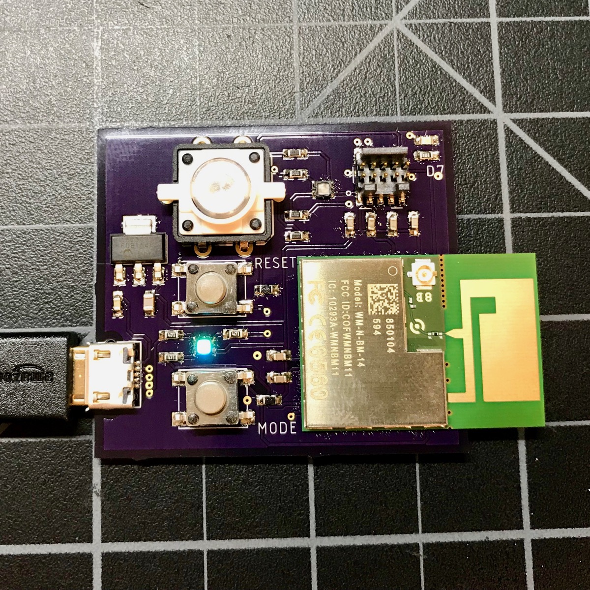
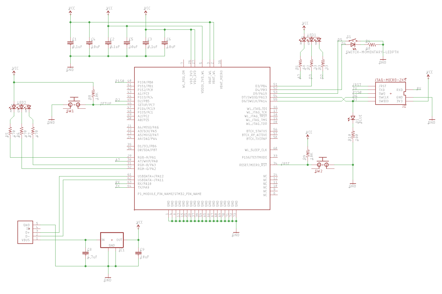
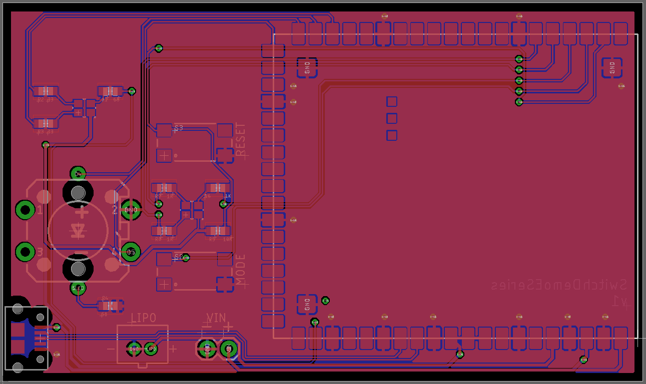
P1 (Gen 2 Wi-Fi SMD)
Making a board for the P1 module is more difficult than the devices we've used so far. It's recommended that you include:
- RGB LED (the status one)
- RESET and MODE buttons
- USB connector
- 3.3V Regulator
To match the other boards, this design includes a second RGB LED and LED button switch. It also includes a 10-pin micro SWD/JTAG connector and the blue D7 LED (optional).
Schematic
Board
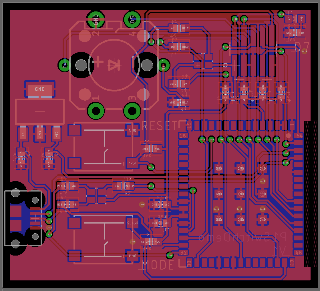
The Eagle CAD schematic and board files are in the eagle directory in the GitHub repository.
Bill of materials (bom)
| Quan | Item | Example | Price |
|---|---|---|---|
| 1 | LED tactile button | SparkFun | $2.10 |
| 2 | RGB LED | Cree CLMVC-FKA-CL1D1L71BB7C3C3 | $0.19 |
| 4 | 33 ohm resistor 0603 | Panasonic | |
| 4 | 68 ohm resistor 0603 | Panasonic | |
| 1 | 100 ohm resistor 0603 | Panasonic | |
| 2 | 10K ohm resistor 0603 | Panasonic | |
| 3 | 0.1uF capacitor 0603 | Panasonic | |
| 1 | 4.7uF capacitor 0603 | Panasonic | |
| 4 | 10uF capacitor 0805 | Panasonic | |
| 1 | MCP1825ST voltage regulator | Microchip | $0.53 |
| 1 | USB Micro B connector | Amphenol FCI 10118194-0001LF | $0.42 |
| 1 | 10-pin JTAG Connector | Samtek SAM8796-ND | $2.90 |
| 2 | Tactile switch | C&K PTS645SH50SMTR92 | $0.21 |
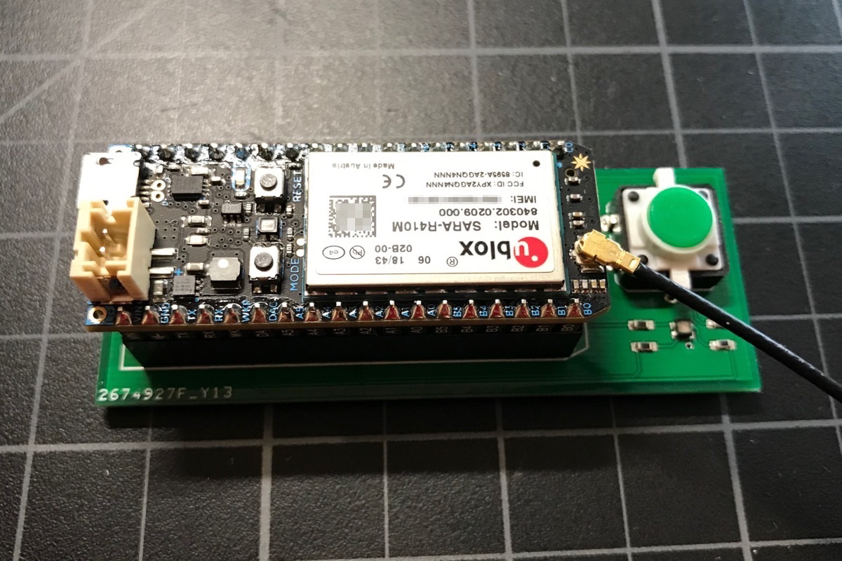
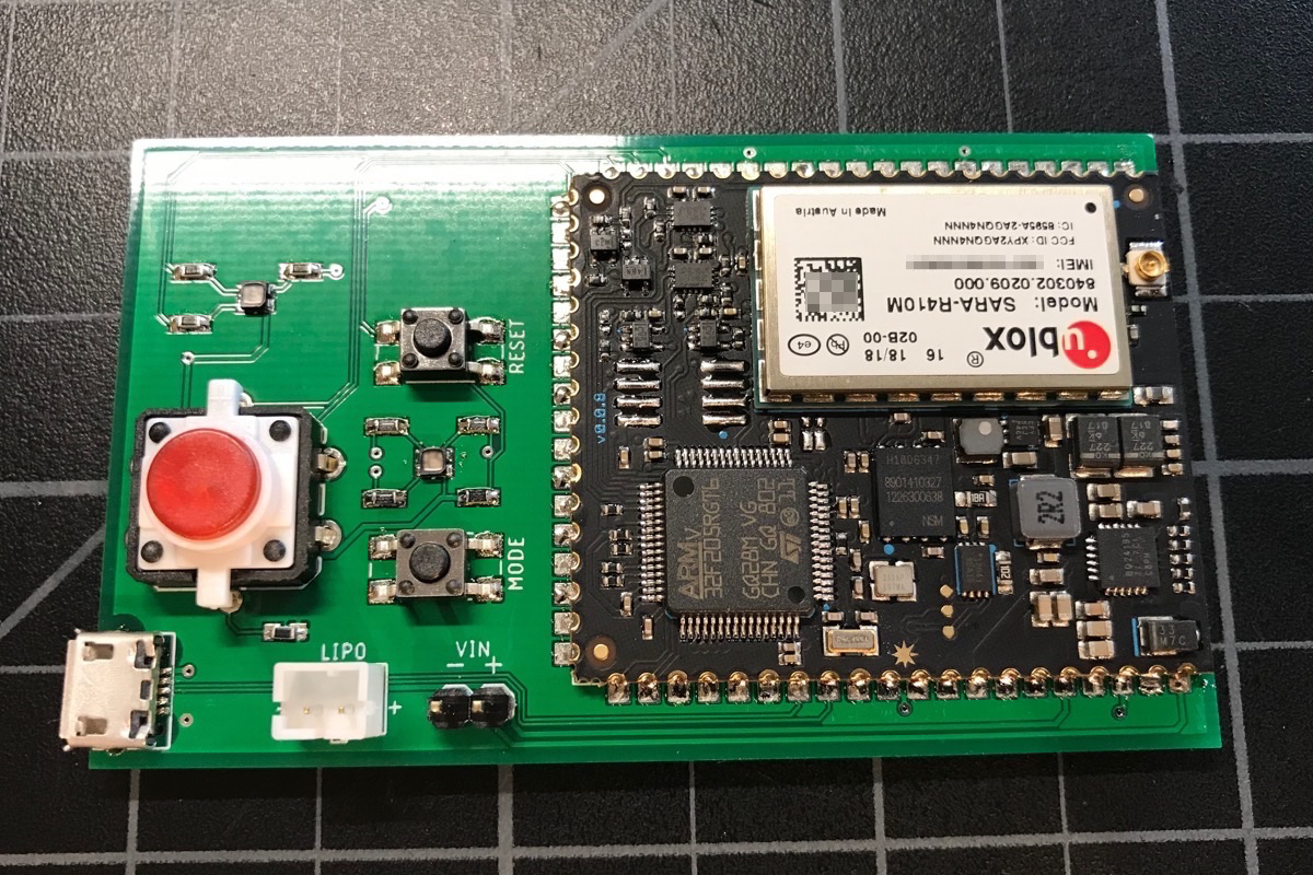
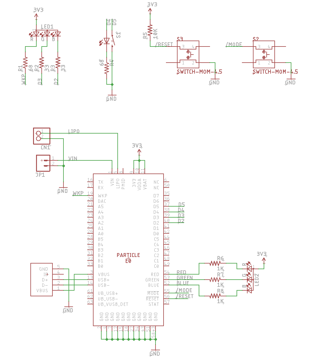
E-Series (Gen 2 cellular SMD)
The E-Series Gen 2 cellular module is about the same level of effort as the P1. It has a built-in voltage regulator and PMIC, but you need to add a battery connector.
- RGB LED (the status one)
- RESET and MODE buttons
- USB connector
- Battery connector
- Charge LED (I forgot to add this in the design here)
Schematic:
Board:
The Eagle CAD schematic and board files are in the eagle directory in the GitHub repository.
Bill of Materials (BOM)
| Quan | Item | Example | Price |
|---|---|---|---|
| 1 | LED tactile button | SparkFun | $2.10 |
| 2 | RGB LED | Cree CLMVC-FKA-CL1D1L71BB7C3C3 | $0.19 |
| 4 | 33 ohm resistor 0603 | Panasonic | |
| 4 | 68 ohm resistor 0603 | Panasonic | |
| 3 | 1K resistor 0603 | Panasonic | |
| 1 | 10K ohm resistor 0603 | Panasonic | |
| 1 | USB Micro B connector | Amphenol FCI 10118194-0001LF | $0.42 |
| 2 | Tactile switch | E-Switch TL3305AF160QG | $0.20 |
| 1 | JST-PH battery connector | JST B2B-PH-K-S-LF-SN | $0.17 |
Publish demo
The publish demo uses publish and subscribe to communicate between demo boards. Each device has its own button color programmed in its device firmware. Pressing the button publishes the color, which shows up on all of the other devices.
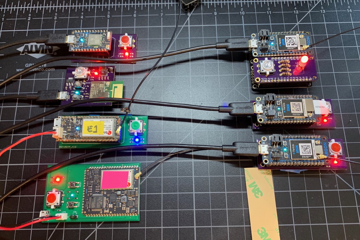
It works between Wi-Fi and cellular devices, across Gen 2 and Gen 3 devices!
#include "Particle.h"

#include "LedSwitchRK.h"

#ifndef SYSTEM_VERSION_v620
SYSTEM_THREAD(ENABLED); // System thread defaults to on in 6.2.0 and later and this line is not required
#endif

SerialLogHandler logHandler;

#if HAL_PLATFORM_MESH
const uint16_t STATUS_RED = A0;
const uint16_t STATUS_GREEN = A1;
const uint16_t STATUS_BLUE = A2;
const uint16_t SWITCH_PIN = D6;
const uint16_t SWITCH_LED_PIN = D5;
#else
const uint16_t STATUS_RED = WKP;
const uint16_t STATUS_GREEN = D3;
const uint16_t STATUS_BLUE = D2;
const uint16_t SWITCH_PIN = D5;
const uint16_t SWITCH_LED_PIN = D4;
#endif

const uint32_t MY_COLOR = 0x00ff00;
// 0xff0000 = red
// 0x00ff00 = green
// 0x0000ff = blue
// 0xFFFF00 = yellow
// 0xFF00FF = magenta
// 0xFFFFFF = white

const char *EVENT_NAME = "switchDemoSet";

LedSwitch ledSwitch(SWITCH_LED_PIN, SWITCH_PIN); // led, switch

void switchDemoHandler(const char *event, const char *data);
void setColor(uint32_t color);

const unsigned long BUTTON_ON_PERIOD = 2000;
unsigned long lastButtonOn = 0;


void setup() {
    pinMode(STATUS_RED, OUTPUT);
    pinMode(STATUS_GREEN, OUTPUT);
    pinMode(STATUS_BLUE, OUTPUT);
    setColor(0x000000); // black/off

    Particle.subscribe(EVENT_NAME, switchDemoHandler, MY_DEVICES);
}

void loop() {
    if (ledSwitch.pressed()) {
        Log.info("button pressed");
        setColor(MY_COLOR);

        lastButtonOn = millis();
        ledSwitch.ledOn();

        char buf[32];
        snprintf(buf, sizeof(buf), "%06lx", MY_COLOR);
        Particle.publish(EVENT_NAME, buf, PRIVATE);
    }

    if (lastButtonOn != 0 && millis() - lastButtonOn >= BUTTON_ON_PERIOD) {
        lastButtonOn = 0;
        ledSwitch.ledOff();
    }

}

void switchDemoHandler(const char *event, const char *data) {
    uint32_t rgbColor;

    if (sscanf(data, "%06lx", &rgbColor) == 1) {
        Log.info("received color 0x%06lx", rgbColor);
        setColor(rgbColor);
    }
    else {
        Log.info("invalid data %s", data);
    }
}

void setColor(uint32_t color) {
    uint8_t red = (uint8_t)((color >> 16) & 0xff);
    uint8_t green = (uint8_t)((color >> 8) & 0xff);
    uint8_t blue = (uint8_t)(color & 0xff);

    // The LED is common anode, so for analogWrite()
    // 0 = full on
    // 128 = half on
    // 255 = off
    //
    // This is opposite of the normal meaning of the LED intensity (0 = off, 255 = full on) so
    // the 255 - factor here.
    analogWrite(STATUS_RED, 255 - red);
    analogWrite(STATUS_GREEN, 255 - green);
    analogWrite(STATUS_BLUE, 255 - blue);
}
The code depends on the LedSwitchRK library.
dependencies.LedSwitchRK=0.0.2
Test firmware
To make it easier to test a single device, I use the test firmware below.
It defaults to fading between colors on the RGB LED. Pressing the button toggles between the various primary RGB colors, and also toggles the LED button on and off.
#include "Particle.h"

#include "LedSwitchRK.h"

#include <cmath>

#ifndef SYSTEM_VERSION_v620
SYSTEM_THREAD(ENABLED); // System thread defaults to on in 6.2.0 and later and this line is not required
#endif

SerialLogHandler logHandler;

//                         red       green     blue      yellow    cyan      magenta   white
uint32_t testColors[7] = { 0xFF0000, 0x00FF00, 0x0000FF, 0xFFFF00, 0x00FFFF, 0xFF00FF, 0xFFFFFF };

#if HAL_PLATFORM_MESH
const uint16_t STATUS_RED = A0;
const uint16_t STATUS_GREEN = A1;
const uint16_t STATUS_BLUE = A2;
const uint16_t SWITCH_PIN = D6;
const uint16_t SWITCH_LED_PIN = D5;
#else
const uint16_t STATUS_RED = WKP;
const uint16_t STATUS_GREEN = D3;
const uint16_t STATUS_BLUE = D2;
const uint16_t SWITCH_PIN = D5;
const uint16_t SWITCH_LED_PIN = D4;
#endif

LedSwitch ledSwitch(SWITCH_LED_PIN, SWITCH_PIN); // led, switch

const unsigned long CHANGE_PERIOD_MS = 10;
unsigned long lastChange = 0;
size_t curColor = -1;
int curDegree = 0;

int ledToggle(String cmd);
void setColor(uint32_t color);
uint32_t HSVtoRGB(int H, double S, double V);

void setup() {
    Wire.begin();

    pinMode(STATUS_RED, OUTPUT);
    pinMode(STATUS_GREEN, OUTPUT);
    pinMode(STATUS_BLUE, OUTPUT);

    Particle.function("led", ledToggle);
}

void loop() {
    if (ledSwitch.pressed()) {
        Log.info("Button pressed");
        ledSwitch.ledToggle();

        if (++curColor >= (sizeof(testColors) / sizeof(testColors[0]))) {
            // -1 = rainbow
            // 0 - n = color in array testColors[curColor]
            curColor = -1;
        }
        else {
            setColor(testColors[curColor]);
        }
    }

    if (curColor == -1) {
        // Rainbows
        if (millis() - lastChange >= CHANGE_PERIOD_MS) {
            lastChange = millis();

            // Use the degrees as the hue in the HSV color space. That's the direction
            // you are pointing on the color wheel.
            //
            // 1.0 is the saturation. 0.0 is at the center of the color wheel (dark) and
            // 1.0 is the outer edge of the color wheel.
            //
            // 0.6 is the value or brightness. 1.0 is the maximum but I turned it down
            // a bit to be less blinding.
            uint32_t color = HSVtoRGB(curDegree, 1.0, 0.6);
            setColor(color);

            if (++curDegree >= 360) {
                curDegree = 0;
            }
        }
    }

}

int ledToggle(String cmd) {

    Log.info("toggling LED from Particle function");
    ledSwitch.ledToggle();

    return 0;
}

void setColor(uint32_t color) {
    uint8_t red = (uint8_t)((color >> 16) & 0xff);
    uint8_t green = (uint8_t)((color >> 8) & 0xff);
    uint8_t blue = (uint8_t)(color & 0xff);

    // The LED is common anode, so for analogWrite()
    // 0 = full on
    // 128 = half on
    // 255 = off
    //
    // This is opposite of the normal meaning of the LED intensity (0 = off, 255 = full on) so
    // the 255 - factor here.
    analogWrite(STATUS_RED, 255 - red);
    analogWrite(STATUS_GREEN, 255 - green);
    analogWrite(STATUS_BLUE, 255 - blue);
}

// Modified from:
// https://gist.github.com/kuathadianto/200148f53616cbd226d993b400214a7f
// H(Hue): 0 - 360 degree (integer)
// S(Saturation): 0 - 1.00 (double)
// V(Value): 0 - 1.00 (double)
uint32_t HSVtoRGB(int H, double S, double V) {
    double C = S * V;
    double X = C * (1 - std::abs(std::fmod(H / 60.0, 2) - 1));
    double m = V - C;
    double Rs, Gs, Bs;

    if(H >= 0 && H < 60) {
        Rs = C;
        Gs = X;
        Bs = 0;
    }
    else if(H >= 60 && H < 120) {
        Rs = X;
        Gs = C;
        Bs = 0;
    }
    else if(H >= 120 && H < 180) {
        Rs = 0;
        Gs = C;
        Bs = X;
    }
    else if(H >= 180 && H < 240) {
        Rs = 0;
        Gs = X;
        Bs = C;
    }
    else if(H >= 240 && H < 300) {
        Rs = X;
        Gs = 0;
        Bs = C;
    }
    else {
        Rs = C;
        Gs = 0;
        Bs = X;
    }

    uint8_t red = (uint8_t)((Rs + m) * 255);
    uint8_t green = (uint8_t)((Gs + m) * 255);
    uint8_t blue = (uint8_t)((Bs + m) * 255);

    return (red << 16) | (green << 8) | blue;
}
The code depends on the LedSwitchRK library.
dependencies.LedSwitchRK=0.0.2