
Mikroe
MikroElektronika has a collection of base boards and small accessory boards, Click, that connect by the mikroBUS.
The mikroBUS connector is has two rows of 8-pin 0.1" pitch headers. The Click boards can be approximately this size, or much longer if more space is needed.
Both the Feather and Gen 3 M.2 SoM Click shields have two mikroBUS sockets.
- SPI (SCK, MOSI, MISO) is shared on both sockets, however each socket has its own CS pin (CS1, CS2).
- I2C is shared on both sockets, but I2C is designed to be used that way.
- Serial is shared on both sockets, but you can generally use only one for serial, unless the serial is unidirectional from the MCU
- Logic levels must be 3.3V to interface with the Argon, Boron or B-Series SoM!
- The mikroBUS socket has both 3.3V and 5V on it.
- The RST1/RST2 pin is used by some click boards to reset the click board. It is unrelated to the nRF52 MCU RST line.
There are a very large number of Click shields available, however there is no set of available libraries like the Sparkfun Qwiic line. One reason is that the Mikroe line is designed around generic ARM processors, not Arduino. While the Arduino library system is different than Particle, the translation is very straightforward and was automated. There currently is no automatic translation of Mikroe libraries to Particle so they need to be done by hand.
For some sensors, for example the TMP102 I2C temperature sensor, there is a library available in the Particle community libraries.
Feather shield
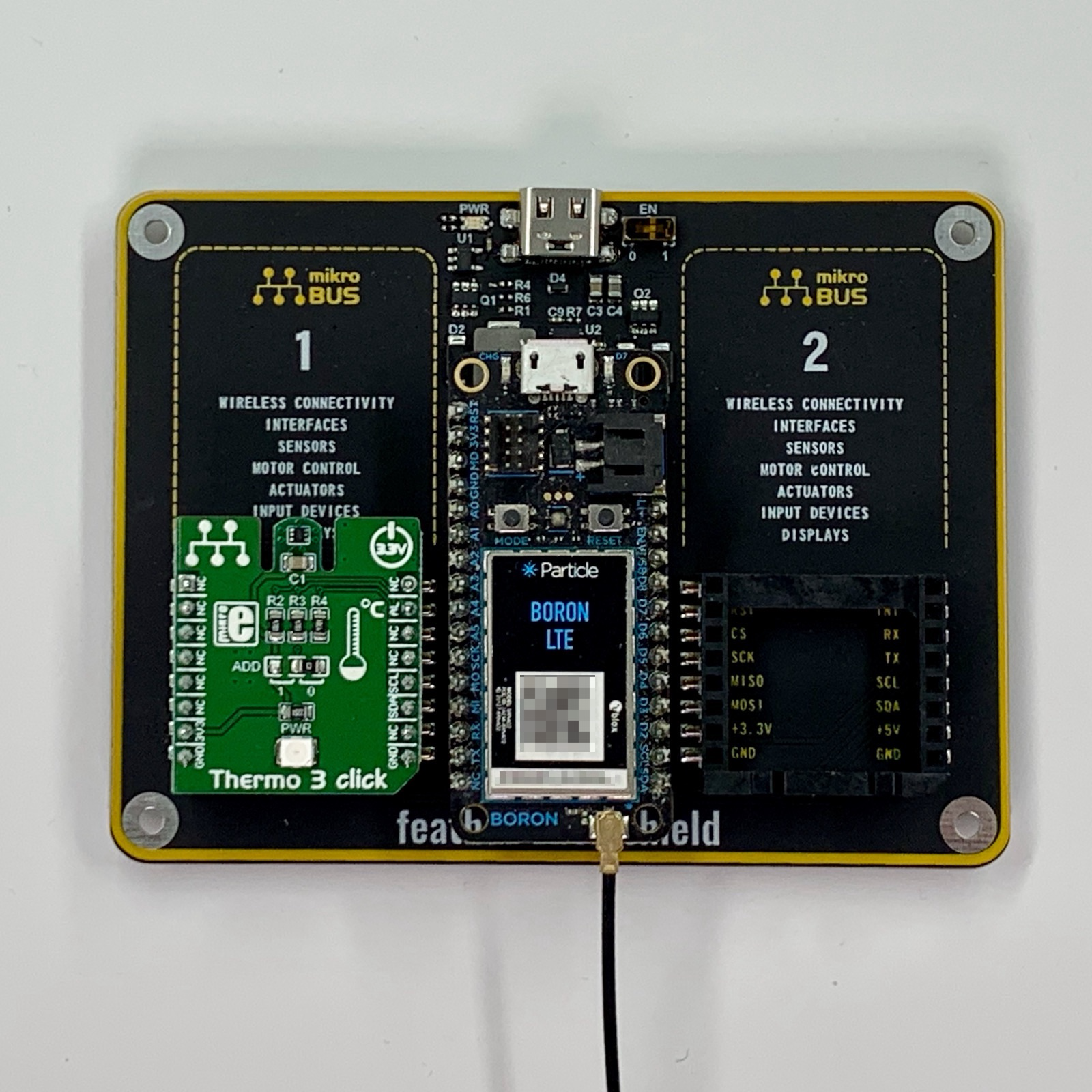
The Feather Click shield has sockets for an Argon or Boron, as well as two Click boards.
Unlike the Adafruit Feather tripler, certain pins (AN, RST, CS, PWM, and INT) are different for each mikroBUS connector.
The Feather pins map to mikroBUS as follows:
| Feather | mikroBUS1 | mikroBUS 2 |
|---|---|---|
| RST | NC | NC |
| 3V3 | +3.3V | +3.3V |
| MD | NC | NC |
| GND | GND | GND |
| A0 | AN1 | NC |
| A1 | NC | AN2 |
| A2 | RST1 | NC |
| A3 | PWM1 | NC |
| A4 | INT1 | NC |
| A5 | CS1 | NC |
| SCK | SCK | SCK |
| MOSI | MOSI | MOSI |
| MISO | MISO | MISO |
| RX | RX | RX |
| TX | TX | TX |
| NC | NC | NC |
| EN | NC | NC |
| USB | +5V | +5V |
| D8 | NC | PWM2 |
| D7 | NC | RST2 |
| D6 | NC | INT2 |
| D5 | NC | CS2 |
| D4 | NC | NC |
| D3 | NC | NC |
| D2 | NC | NC |
| SCL | SCL | SCL |
| SDA | SDA | SDA |
This table just shows the socket-specific pin mapping:
| mikroBUS | Feather |
|---|---|
| AN1 | A0 |
| RST1 | A2 |
| PWM1 | A3 |
| INT1 | A4 |
| CS1 | A5 |
| AN2 | A1 |
| RST2 | D7 |
| PWM2 | D8 |
| INT2 | D6 |
| CS2 | D5 |
Gen 3 SoM shield
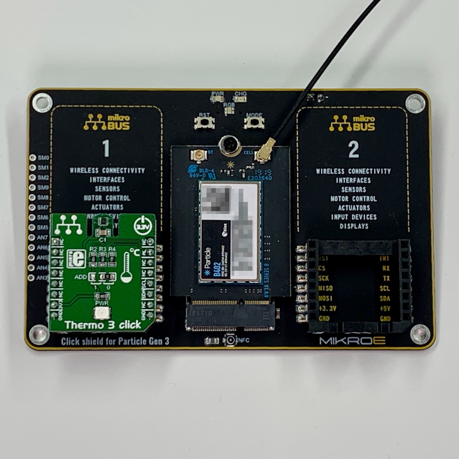
The Gen 3 SoM shield connects a B-Series SoM to mikroBUS Click boards:
| M.2 Pin | Generic SoM | Gen 3 | mikroBUS #1 | mikroBUS #2 |
|---|---|---|---|---|
| 20 | SCL | D1 | SCL | SCL |
| 22 | SDA | D0 | SDA | SDA |
| 23 | ADC0 | A0 | RST2 | |
| 33 | ADC1 | A1 | AN1 | |
| 35 | ADC2 | A2 | AN2 | |
| 36 | TX | TX/D9 | TX | TX |
| 37 | ADC3 | A3 | ||
| 38 | RX | TX/D10 | RX | RX |
| 41 | ADC4 | A4 | ||
| 43 | ADC5 | A5 | ||
| 45 | ADC6 | A6 | ||
| 47 | ADC7 | A7 | ||
| 48 | CS | D8 | CS1 | |
| 50 | MISO | MISO/D11 | MISO | MISO |
| 52 | MOSI | MOSI/D12 | MOSI | MOSI |
| 54 | SCK | SCK/D13 | SCK | SCK |
| 62 | GPIO0 | D22 | INT1 | |
| 64 | GPIO1 | D23 | INT2 | |
| 66 | PWM0 | D4 | CS2 | |
| 68 | PWM1 | D5 | PWM1 | |
| 70 | PWM2 | D6 | PWM2 | |
| 72 | PWM3 | D7 | RST1 |
This table just shows the socket-specific pin mapping:
| mikroBUS | Feather |
|---|---|
| AN1 | A1 |
| RST1 | D7 |
| PWM1 | D5 |
| INT1 | D22 |
| CS1 | D8 |
| AN2 | A2 |
| RST2 | A0 |
| PWM2 | D6 |
| INT2 | D23 |
| CS2 | D4 |
Click boards
CAN
If you wish to implement CAN (controller area network) with the Mikroe system, you should use the MCP2515 CAN SPI click 3.3V, not the MCP25625 click. The Particle library supports both, but the MCP25625 click defaults to 5V IO and you need to move a SMD resistor on the click board to change it. The MCP2515 has 3.3V IO which is required by nRF52 devices and works out of the box. The software is completely compatible so you can prototype with the MCP2515 and seamlessly transition to the MCP25625 on a custom board if desired.
Example
Gen 3 SoM shield with TMP102 temperature sensor
This is a simple example that uses the Thermo-3-click temperature sensor.
- It uses I2C to communicate with TMP102 temperature sensor running at 3.3V
- I2C Address 0x48. Can be reconfigured to 0x49 by moving a 0-ohm resistor
- The INT pin is an output from the TMP102 to indicate a temperature alarm
The INT pin on each Click board is wired separately to the MCU. The Particle pin is as follows:
| Shield | Socket | INT Pin |
|---|---|---|
| M.2 SoM | #1 | D22 |
| M.2 SoM | #2 | D23 |
| Feather | #1 | A4 |
| Feather | #2 | D6 |
Using the INT pin for a temperature alarm is optional, however the example uses this feature.
Here's the code
Be sure to add the SparkFunTMP102 library to your project, such as by using Particle: Install Library in Particle Workbench.
The USB serial debug log might look something like this:
0000080001 [app] INFO: tempF=73.1
0000090001 [app] INFO: tempF=73.1
0000100001 [app] INFO: tempF=73.2
0000104373 [app] INFO: temperature alarm triggered
0000110001 [app] INFO: tempF=75.2
0000120001 [app] INFO: tempF=74.1
0000126260 [app] INFO: temperature alarm cleared
0000130001 [app] INFO: tempF=73.8