Automation HATs
This page covers HATs used in home automation
Pimoroni automation HAT
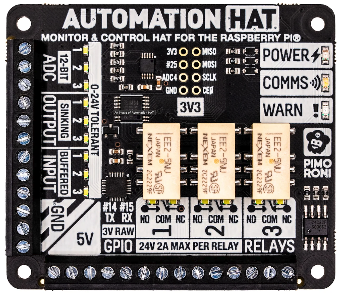
This hat includes a large number of inputs and outputs. (Pimoroni, Adafruit).
- 3 x 24V @ 2A relays (NC and NO terminals)
- 3 x 12-bit ADC @ 0-24V (±2% accuracy)
- 3 x 24V tolerant buffered inputs
- 3 x 24V tolerant sinking outputs
- 15 x channel indicator LEDs
- 1 x 12-bit ADC @ 0-3.3V (not available on Muon!)
- 3.5mm screw terminals

The pinout is as follows:
Note that both 3V3 (for logic) and 5V (for relays and LEDs) are used on this board.
There are two chips connected by I2C on the HAT:
| Chip | Description | I2C Address |
|---|---|---|
| SN3218 | 18-channel LED driver | 0x54 |
| ADS1015 | Analog to digital converter | 0x48 |
The ADS1015 ADC cannot be accessed on the Muon. The problem is that I2C Address 0x48 is used by both the ADS1015 on the automation HAT as well as the TMP112A temperature sensor on the Muon itself. These will conflict with each other, allowing neither to be used.
The LEDs are controlled by a SN3218 LED driver chip. The SN3218_RK library can be used to manage the LEDs.
Sample code
This sample code shows how to set outputs (relay or digital) and get digital input values.
It implements a Particle.function to set the digital and relay output values. In also implements a Particle.variable to get the digital input values.
ADC - Pimoroni automation HAT
ADC inputs 1 - 3 cannot be used on the Muon. The problem is that I2C Address 0x48 is used by both the ADS1015 on the automation HAT as well as the TMP112A temperature sensor on the Muon itself. These will conflict with each other, allowing neither to be used.
Digital inputs - Pimoroni automation HAT
Digital inputs Input 2 and Input 3 can be read using digitalRead(). The value will be HIGH or LOW (1 or 0, respectively).
Digital Input 1 cannot be read with Device OS 5.9.0 as it does not allow reading of pins from the I/O expander (IOEX_PB7) at this time.
When using the sample code above, you can request the variable named input and it will return a JSON object with the input values:
% particle variable get my-muon input
{"input2":0,"input3":0}
You can also request variables from the Particle console in the device view.
Digital outputs - Pimoroni automation HAT
All three digital output can be used. Note that you must set the pinMode once (typically during setup) before you can use digitalWrite.
pinMode(A0, OUTPUT);
digitalWrite(A0, HIGH);
When using the sample code above, you can call the function output and it will allow you to set one or more values:
% particle call my-muon output '{"output1":1}'
% particle call my-muon output '{"output1":0,"output2":1}'
Note that the digital outputs (output1, output2, output3) are low-side sink outputs, meaning they provide the connection to GND when turned on. If you are testing the output using a digital multimeter, put it in resistance (ohm) mode, and measure the resistance between the output and GND. If 0 Ω then the output is turned on (1).
Relays - Pimoroni automation hat
All three relays can be activated using the GPIO in the table above. Note that you must set the pinMode once (typically during setup) before you can use digitalWrite.
pinMode(D4, OUTPUT);
digitalWrite(D4, HIGH);
When using the sample code above, you can call the function output and it will allow you to set one or more values:
% particle call my-muon output '{"relay1":1}'
% particle call my-muon output '{"relay1":0,"relay2":1,"output1":1}'
LEDs - Pimoroni automation hat
The LEDs are controlled by a SN3218 LED driver chip. The SN3218_RK library can be used to manage the LEDs.
When using the sample code above, you can call the function output and it will allow you to set one or more LEDs on or off:
% particle call my-muon output '{"led0":1}'
% particle call my-muon output '{"led0":0,"led3":1}'
You can also set the PWM (brightness) value from 0 - 255. The sample code sets it to 128 during setup.
% particle call my-muon output '{"pwm0":255,"led0":1}'
