RS485 (Modbus) and CAN HAT
There are a number of widely available RS485 (Modbus) and CAN HATs available.
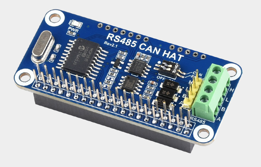
Testing was done with Waveshare RS485 CAN HAT for Raspberry Pi 5/4B/3B+/3B/2B/B+/Zero/Zero W/WH/Zero 2W, Long-Distance Communication via RS485/CAN Function Onboard CAN Controller MCP2515 via SPI Interface Transceiver SIT65HVD230DR (from Amazon, Waveshare) however it should be compatible with most similar devices with the MCP2515 or MCP25625 CAN controller.

This board uses the SIT65HVD230DR CAN transceiver and the SP3485 RS485 transceiver, but the driver software does not depend on the transceiver so you can use generally use boards with any transceiver chips.
The pinout is straightforward and described in more detail below.

This page is divided into two parts because you will generally use RS485 or CAN, but not both, but you could use both if desired
RS485 (Modbus)
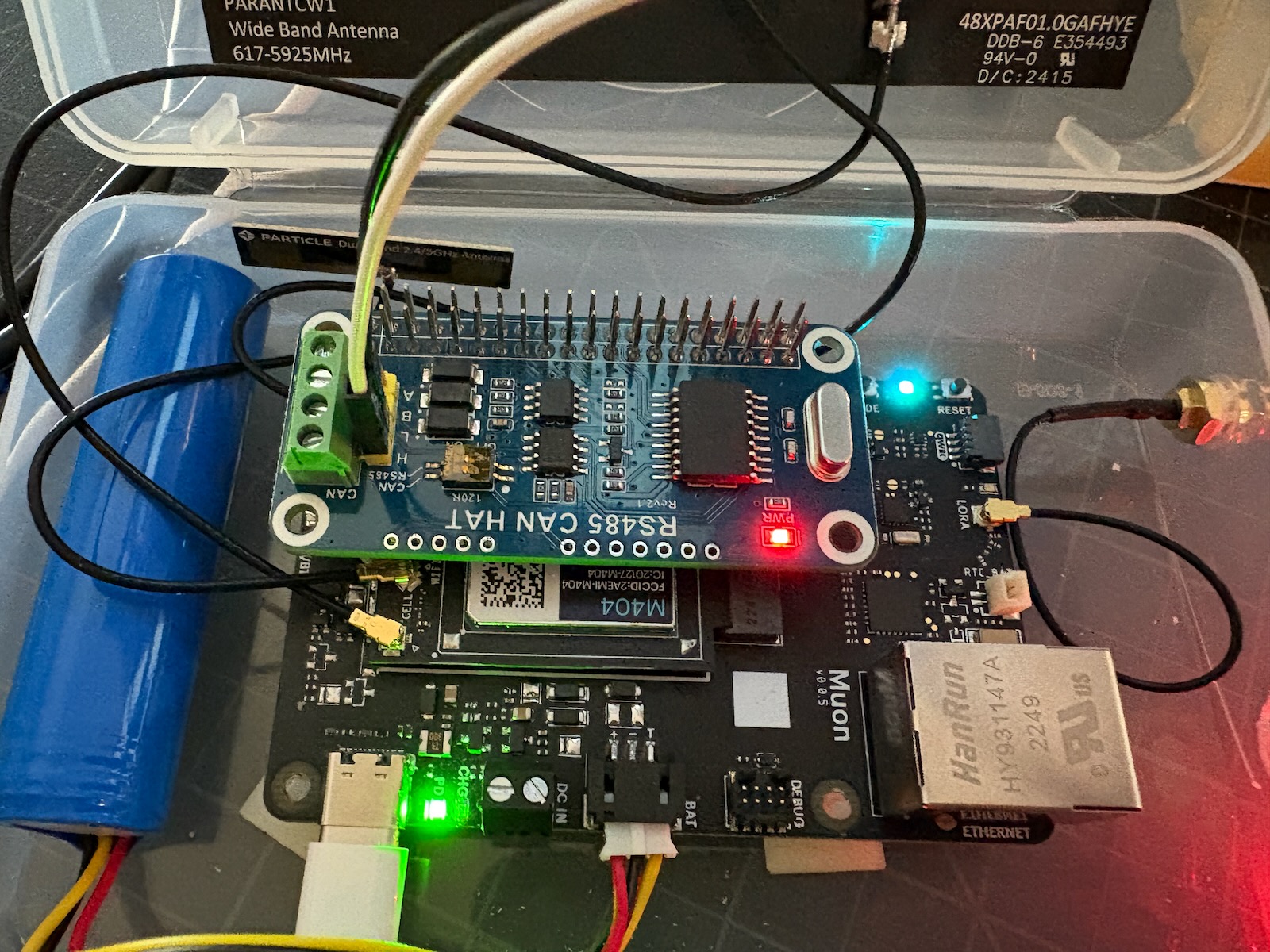
On this board, the RS485 pins are labeled A and B; this is typical for most RS485 implementations. As RS485 is differential, there is no ground connection.
The RX and TX lines are mapped to the expansion connection RX and TX pins, which are Serial1 on the Muon.
This particular board has auto-direction sensing for the RS485 interface, which is recommended. It is possible to configure this board to use manual direction control using Raspberry Pi GPIO, but this requires soldering. It is mapped to expansion pin 7, GPIO4 (GPCKL0). This is Muon IOEX_PA0, which is not directly accessible to Device OS 5.9.0.
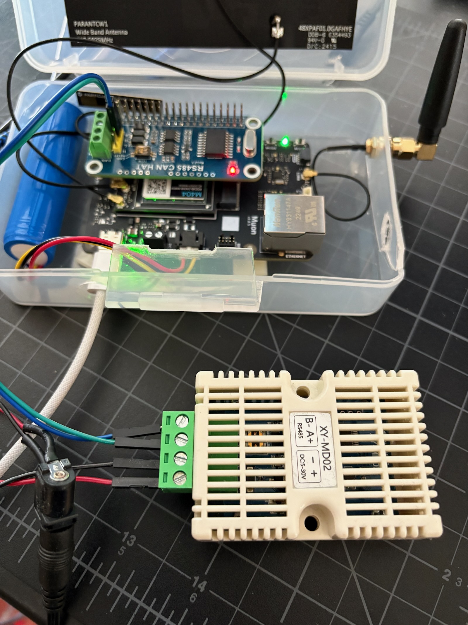
Modbus example project
This is a simple example project that reads a Modbus temperature and humidity sensor.

CAN
On this board, the CAN pins are labeled H and L; this is typical for most CAN bus implementations. As CAN bus is differential, there is no ground connection.
The CAN controller chip connects by SPI (SCK, MOSI, and MISO). It uses expansion connector pin 24, GPIO8 (CE0), which maps to Muon pin A6.
It can optionally use an interrupt output, connected to expansion connector pin 22 (GPIO25). This maps to Muon pin D22.
This board comes with a 12 MHz crystal. You will need to note the frequency of the crystal (generally stamped on the metal can) on your board and configure the software appropriately. 8 MHz, 16 MHz, and 20 MHz are also common.
| Crystal | Constant |
|---|---|
| 20 MHz | MCP_20MHz |
| 16 MHz | MCP_16MHz |
| 12 MHz | MCP_12MHz |
| 8 MHz | MCP_8MHz |
You will also need to select the speed of your CAN bus. OBD-II on vehicles is generally 500 Kbits/sec,
| Speed | Constant |
|---|---|
| 5 Kbits/sec | CAN_5KBPS |
| 10 Kbits/sec | CAN_10KBPS |
| 20 Kbits/sec | CAN_20KBPS |
| 25 Kbits/sec | CAN_25KBPS |
| 31.25 Kbits/sec | CAN_31K25BPS |
| 33 Kbits/sec | CAN_33KBPS |
| 40 Kbits/sec | CAN_40KBPS |
| 50 Kbits/sec | CAN_50KBPS |
| 80 Kbits/sec | CAN_80KBPS |
| 83.3 Kbits/sec | CAN_83K3BPS |
| 95 Kbits/sec | CAN_95KBPS |
| 100 Kbits/sec | CAN_100KBPS |
| 125 Kbits/sec | CAN_125KBPS |
| 200 Kbits/sec | CAN_200KBPS |
| 250 Kbits/sec | CAN_250KBPS |
| 500 Kbits/sec | CAN_500KBPS |
| 666 Kbits/sec | CAN_666KBPS |
| 1000 Kbits/sec | CAN_1000KBPS |
Some less common speeds like 31.25 Kbits/sec are not possible with some crystal frequencies. Standard speeds like 100, 200, 250, 500, and 1000 Kbits/sec. are widely supported.
The can-mcp25x library used for CAN is also used on the Tracker SoM, Tracker One, and Monitor One.
CAN example project
This is a simple example project that reads the engine RPM from OBD-II via CAN.
Viewing the USB serial debug log should yield something like:
0000234192 [app] INFO: engineRPM 0
0000236192 [app] INFO: engineRPM 1500
0000238192 [app] INFO: engineRPM 1500
0000240192 [app] INFO: engineRPM 2508
0000242192 [app] INFO: engineRPM 2504

