B-Series SoM First Board
This tutorial will guide you through some things that may help in making your first SoM base board design.

There are a number of features that are different between the Boron and B-Series SoM:
| Feature | Boron | B-Series SoM | SoM Base Board | E-Series |
|---|---|---|---|---|
| U.FL Antenna Connector | ✓ | ✓ | Optional | ✓ |
| MFF2 SMD Particle SIM | ✓ | ✓ | ✓ | |
| Nano 4FF SIM card connector | ✓ | |||
| USB Connector | ✓ | Optional | ||
| Status LED | ✓ | Optional | ||
| Reset and Mode Buttons | ✓ | Optional | ||
| Battery Connector | ✓ | Optional | ||
| PMIC and Fuel Gauge | ✓ | Optional | ✓ |
In particular, you'll need to handle:
- Voltage regulation
- USB (optional)
- RGB Status LED (optional)
- Reset and Mode Buttons (optional)
Unlike the E-Series module, the B-Series SoM does not include the PMIC (Power Management IC, bq24195) and fuel gauge (MAX17043). There are several reasons for this:
- The PMIC is not necessary for devices that are externally powered, such as by power mains, or a vehicle power supply.
- For specific applications like solar, there are different PMICs with better performance.
- The MAX17043 can only be used for 3.6V LiPo batteries. For other technologies, like LiSOCL2 disposable batteries or lead-acid batteries, different fuel gauge chips are required.
By moving these features off the module, you can more easily customize your design.
Note:
First board and basic design examples are intended to be easily hand-assembled on inexpensive 2-layer circuit boards using easily available parts. They are not intended to be reference examples of best practices for electronic design.
Basic design
The SoM base board in this tutorial is about as simple as you can build. It does not have a fuel gauge or PMIC, and is powered by USB only, with no battery support. There will be other tutorials for more complex power supply designs.
The main part of the design includes the M.2 (NGFF) SoM connector, micro USB connector, RGB LED, RESET and MODE buttons.
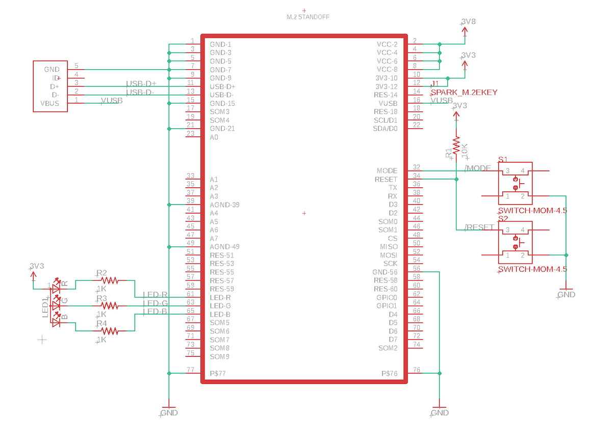
The rest of the design is the power supply. It uses a MP2122A dual voltage regulator to produce 3.3V (for the nRF52840) and 3.8V (for the cellular modem). You can supply it with 3.6V to 6.0V from USB or an external power supply. You can also remove some jumpers to substitute a different power supply for testing.
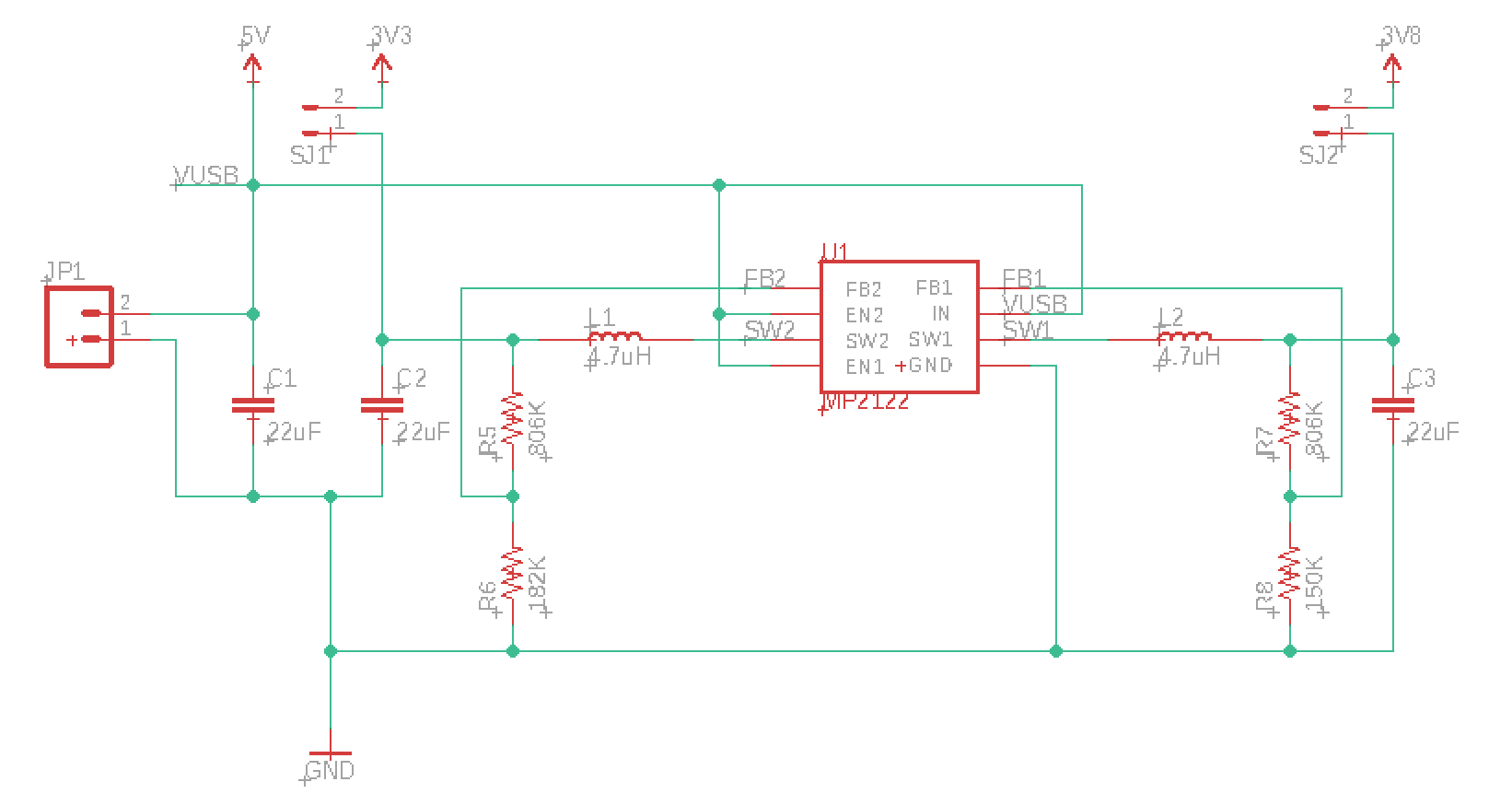
The MP2122A can supply 2A to satisfy all current cellular modules. The B402 only requires 500 mA, but it's best to include enough power in case you want to switch modules in the future.
This is the Eagle board design for the USB SoM base board:
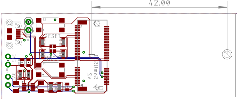
It's a two-layer board so it is easy and inexpensive to manufacture, and you can work with it on the free version of Eagle CAD.
The Eagle CAD design files can be downloaded from:
https://github.com/particle-iot/docs-tutorials
RGB Status LED
We recommend including the RGB status LED as it is very difficult to see what the device is doing without it.
Device OS assumes a common anode RGB LED. This design uses a Cree CLMVC-FKA-CL1D1L71BB7C3C3 which is inexpensive and easily procured.
The design includes 1K current limiting resistors. These are much larger than necessary. They make the LED less blinding but still provide sufficient current to light the LEDs. If you want maximum brightness you should use the calculated values, 33 ohm on red, and 66 ohm on green and blue.
Buttons
The RESET and MODE buttons are highly recommended as well. Even if you don't include the buttons, having a way to trigger them, such as by test points, is beneficial.
The RESET line must have a 10K pull-up resistor to 3V3, but the MODE button does not need one.
This design uses an E-Switch TL3305AF160QG which is a 4.5mm SMD tactile button switch. It's much larger than the switch on the Boron but much easier to manipulate with your fingers.
You may want to use a smaller switch on your boards to save space.
USB Connector
A USB connector is highly recommended for software updates, serial debugging, and low-level operations like resetting keys.
This design uses an Amphenol FCI 10118194-0001LF SMD USB micro B receptacle. This is the same style of USB connector as on all Particle devices and evaluation boards.
Power supply
This design uses a Monolithic Power Systems MP2122AGJ-Z dual 2A adjustable switching regulator, or the older MP2122GJ-Z (no "A").
Each output is controlled by a voltage divider (two resistors), has an inductor (4.7 uH), and an output capacitor (22 uF). There's also a 22 uF input capacitor.
Voltage regulators are currently affected by supply chain issues. There's quite a bit of flexibility to choose a different regulator, but make sure it provides sufficient power, particularly on the 3V7 line (3.7 to 4.2V at 2A).
M.2 Connector
The SoM connector is a M.2 (NGFF) 67-position connector. We recommend the TE Connectivity/AMP Connectors 2199230-4.
Note that there are different key configurations for the M.2 connector. Make sure you use the -4 (E style) key configuration. Computer SSDs (solid-state drives) use a different key style.
The M.2 connector is not designed for repeated insertion and removal so you should avoid removing the SoM too often if possible.
Make sure you don't place any components on the top side of your base board underneath the SoM. Since the B series SoMs are two-sided, the RF shielding may hit components under the SIM, preventing the SoM from seating properly. It fine to put ground plane or traces in that zone, and you could put components on the underside of your base board, if you needed to.
Hold-down screw
The hold-down screw really is required! The M.2 connector does not have integrated locks, so if you don't have the hold-down screw, the module will pop right up again. This also means you cannot make a board that stops at the M.2 connector; it needs to be at least 42mm longer for the hold-down.
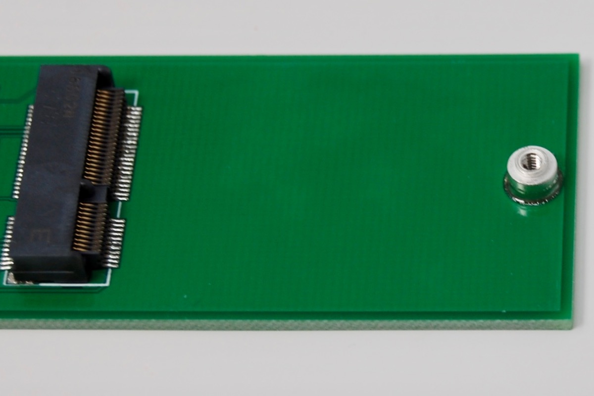
This design uses a JAE SM3ZS067U410-NUT1-R1200 standoff. It's reflow soldered to your base board and has a threaded hole for a M2*3 screw to hold down the SoM.
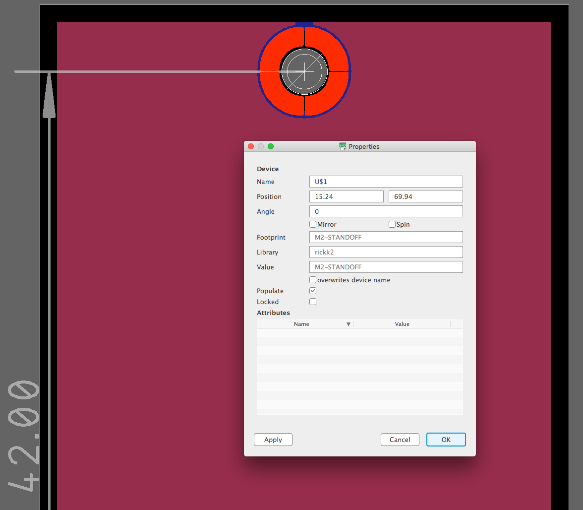
In Eagle, you can position the screw hole on your board as follows:
- Place the M2 Standoff component on your schematic.
- Set the grid to mm on the board layout.
- Right click on the + in the middle of the M.2 connector and select Properties. Note the position (X=12.7mm, Y=27.94mm).
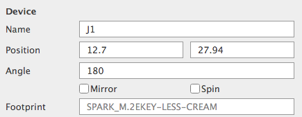
- Set the X position of the standoff to be the same as the M.2 connector (12.7 in this case), and the Y position to be 42mm higher. In this example: 27.94 + 42.0 = 69.94
- Add a dimension line if desired.
- Switch the grid back to inches or mils (if desired).
This is what the standoff looks like soldered to the top side of the base board:
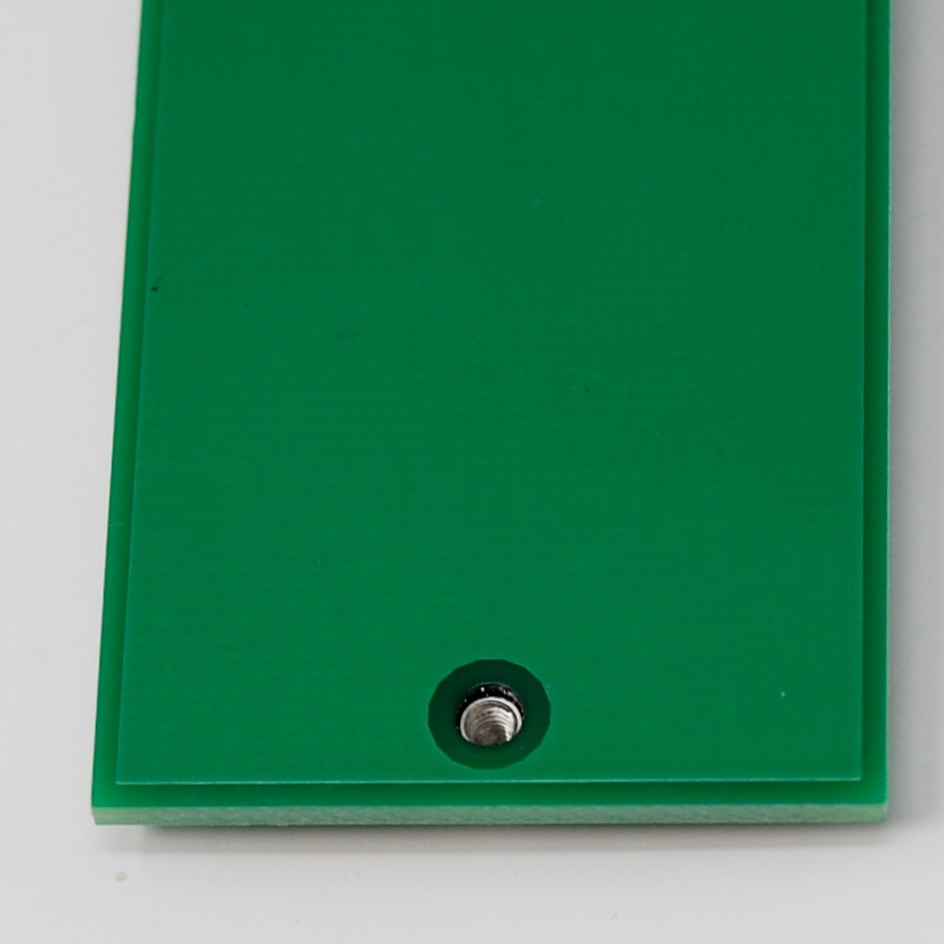
And the bottom:
The best option for the screw is to use a M2*3 (M2 2mm screw, 3mm long) with a 4mm head. This is a larger head screw, commonly used with computer SSD drives.
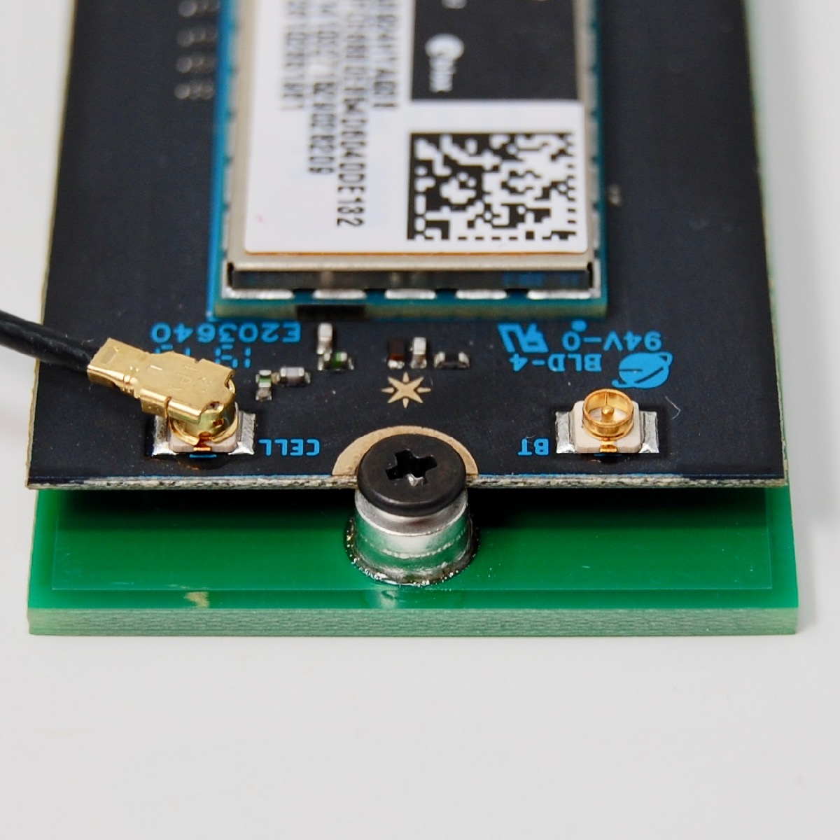
You can use a standard M2*3 screw, but you'll probably want to use a M2 washer as well because the screw head isn't quite large enough to fit securely.
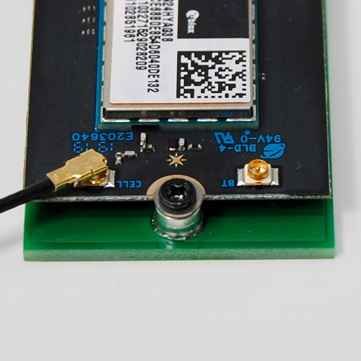
With the proper standoff and screw the SoM will be level with the board and the RF shield on the bottom will not touch the base board.
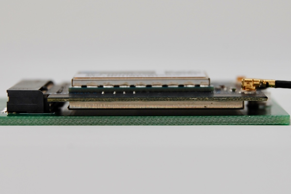
Some of the pictures are taken using a 3mm hole for a M3 x 6mm screw and M3 nut. That will work in a pinch, but the standoff above is much more secure.
BoM (Bill of Materials)
| Quan | Part | Example | Price |
|---|---|---|---|
| 3 | 1K resistor 0603 | Panasonic ERJ-PB3D1001V | |
| 1 | 10K resistor 0603 | Panasonic ERJ-PA3J103V | |
| 1 | 150K resistor 0603 1% | Panasonic ERJ-3EKF1503V | |
| 1 | 182K resistor 0603 1% | Panasonic ERJ-3EKF1823V | |
| 2 | 806K resistor 0603 1% | Panasonic ERJ-3EKF8063V | |
| 3 | 22 uF capacitor 0805 | Murata GRM219R61A226MEA0D | |
| 2 | 4.7 uH inductor 1008 | Bourns CVH252009-4R7M | $0.26 |
| 2 | 4.5mm tactile switch | E-Switch TL3305AF160QG | $0.20 |
| 1 | USB micro B connector | Amphenol FCI 10118194-0001LF | $0.42 |
| 1 | RGB LED 4PLCC | Cree CLMVC-FKA-CL1D1L71BB7C3C3 | $0.19 |
| 1 | MP2122A Regulator | Monolithic Power Systems MP2122AGJ-Z | $2.38 |
| 1 | M.2 connector | TE Connectivity 2199230-4 | $1.42 |
| 1 | M.2 standoff | JAE SM3ZS067U410-NUT1-R1200 | $1.25 |
| 1 | M2*3 screw w/4mm head | example | |
| Male header pins 0.1" | Sullins PRPC040SAAN-RC |
Assembly
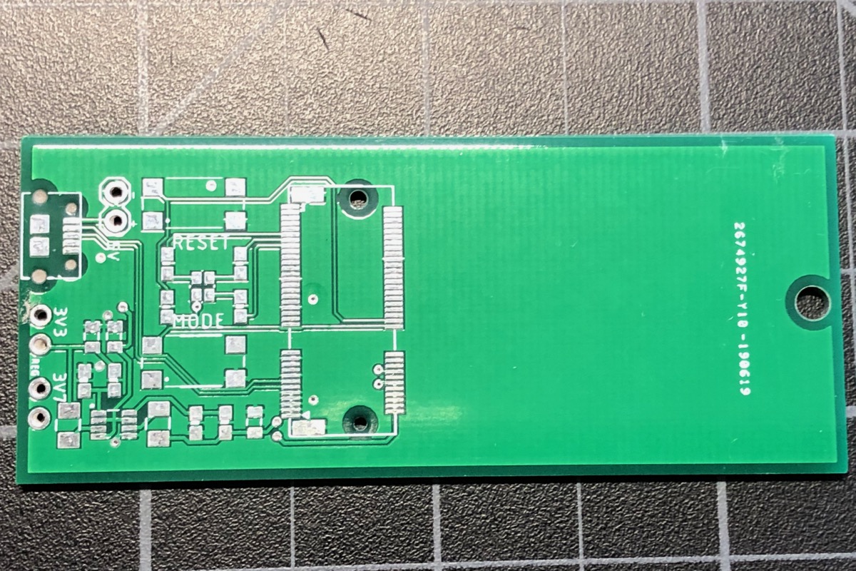
This is the board that I received from JLCPCB. I've also ordered many boards from OshPark; some of the pictures below have purple boards and those are from OshPark.
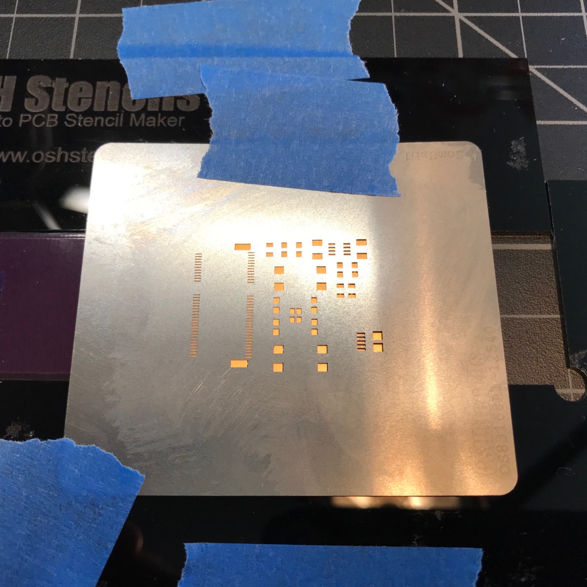
When using the M.2 connector you will almost certainly need a stencil. I ordered mine with my board from JLCPCB, but if you order a board from OshPark you can get the stencil separately from Osh Stencils.
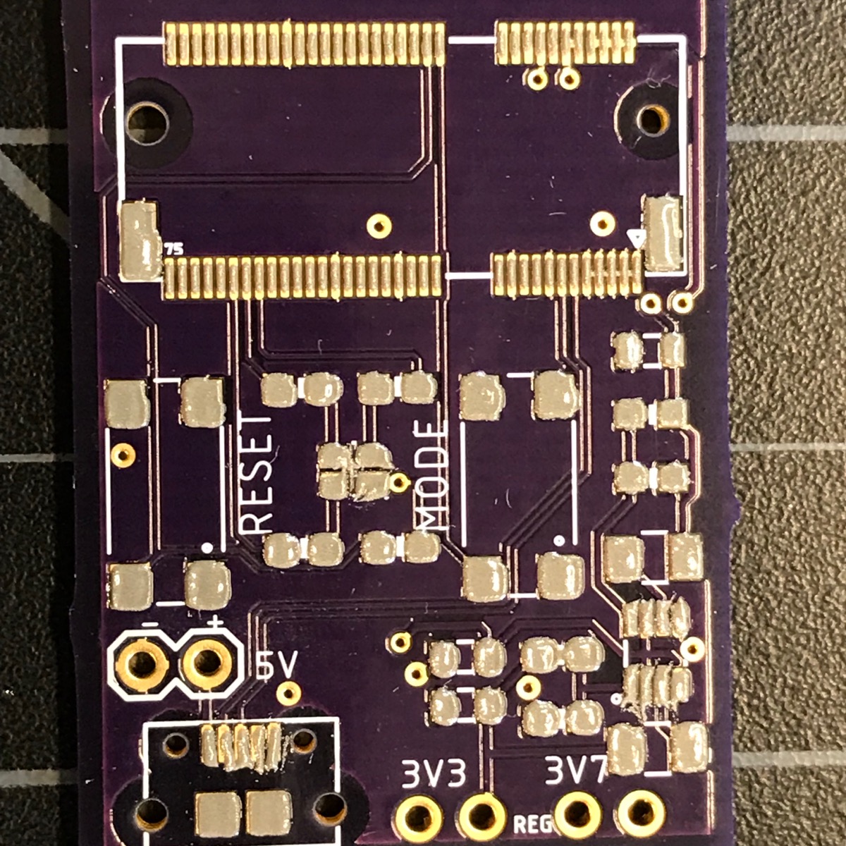
Since I used a 5 mil stainless steel stencil I frequently end up with too much solder paste on some of the tight pins. For example, here on the MP2122A. It's a good idea to clean this up; I use a small dental-style scraper tool for this.
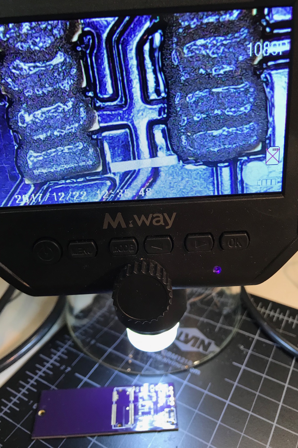
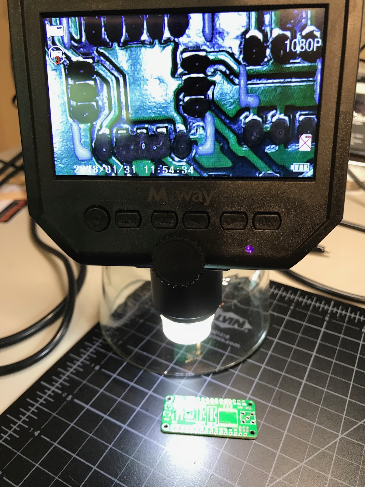
These inexpensive digital microscopes are ideal for assembling boards. I prefer this style with the integrated display vs. the ones that connect to a laptop. There's generally less lag with these, which makes it possible to do assembly and adjustment under the microscope while looking at the screen.
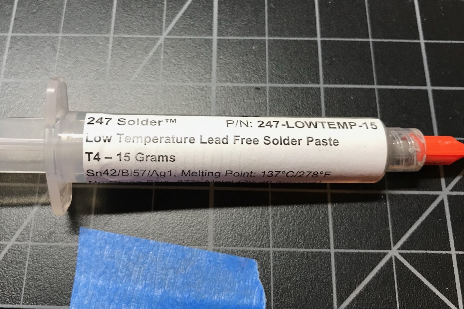
I prefer to use low-temperature lead-free solder paste, in this case Sn42/Bi57/Ag1 with a melting point 137°C (278°F).
Here's the board cleaned up and ready for parts.
This board uses 0603-sized components that are easily placed by hand. I use these two tools, but some prefer tweezers over forceps.

This is my placement guide for the components:
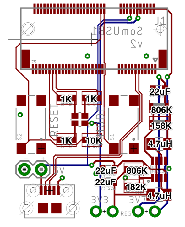
Don't forget to place the M.2 standoff. The rings are not the same size and if you place it upside-down it won't fit flush with the board.
Reflow
I used an inexpensive T962 reflow oven to build this board. It's not the most accurate and there are some hot and cold zones, but works fine here.
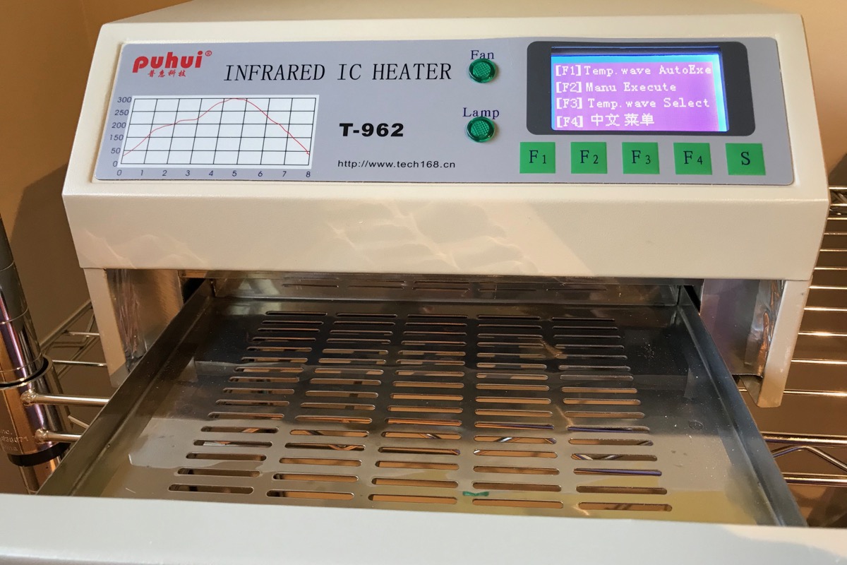
The Sn42/Bi57/Ag1 low-temperature solder paste can be reflowed using Wave 1.
Add the PTH components
There are three two-pin male headers on this board. These get soldered on by hand after the board is reflowed. They're cut from breakable male header pin strips.
The 3V3 and 3V8 connectors will eventually get 2-pin jumpers, but not quite yet.
Testing
Check for solder bridges
The M.2 connector has pins that are very close together and are prone to solder bridges.
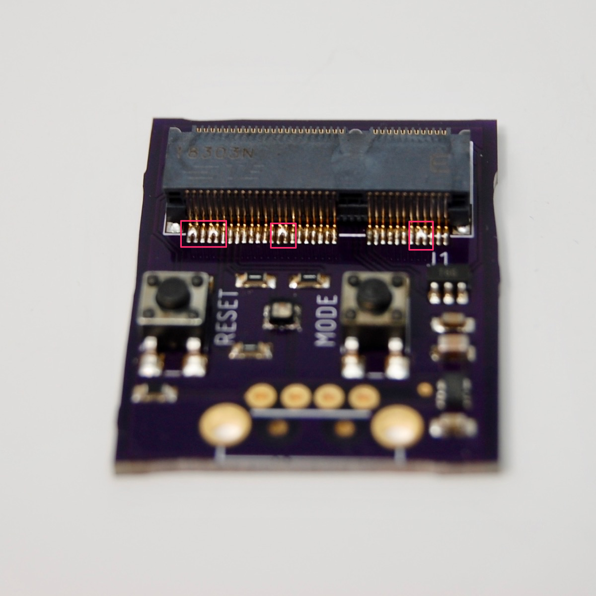
The footprint in this design uses the "-less-cream" version which has a much smaller area of solder paste on the pads of the M.2 connector. This works well for me with 5 mil stainless steel stencils.
If you are using 3 mil polyimide film stencils you may not have enough cream, in which case you might want to try the other version.
Note there are a bunch of power pins that are connected together. It's OK if there are solder bridges there.
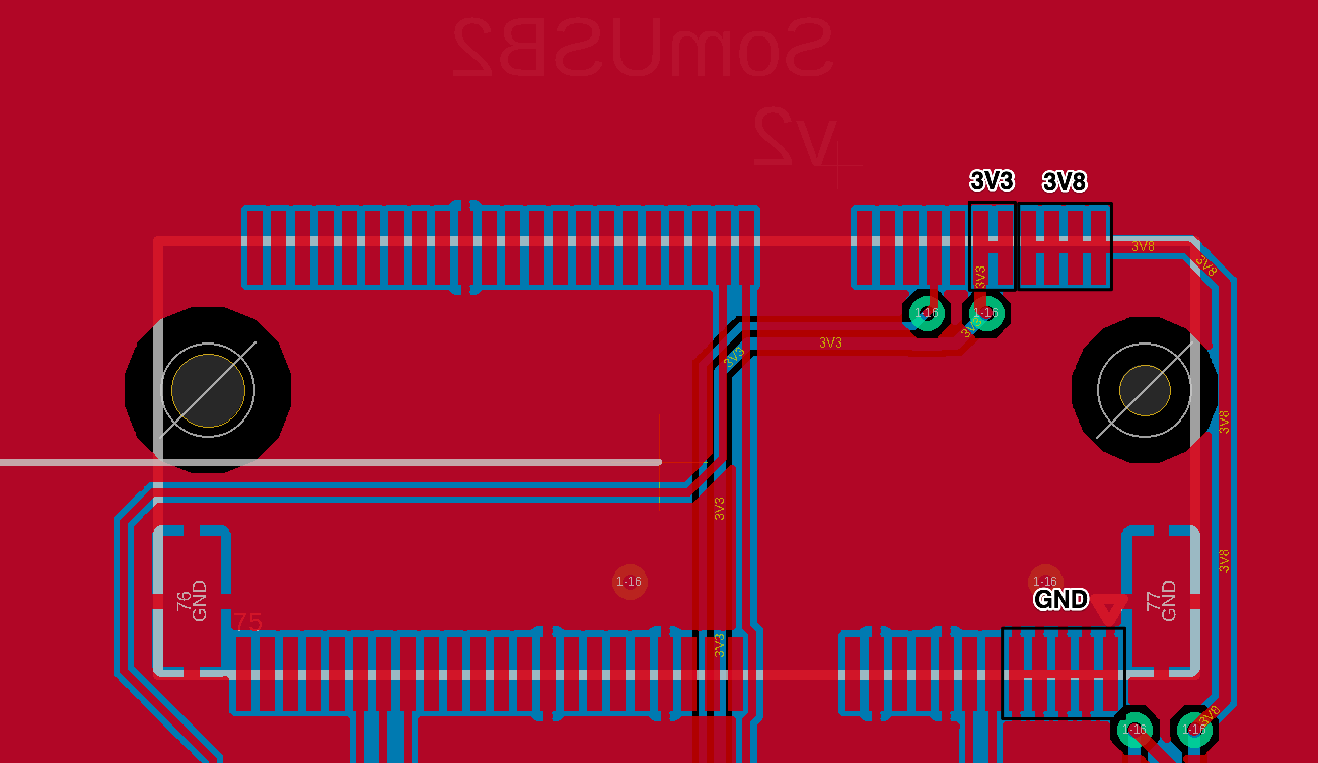
Of course you should do a visual check all of the other components as well; the microscope is handy for that.
Check resistors and capacitors
When you're starting out, it doesn't hurt to check the resistors to make sure they're not shorted and are the right value. Same for capacitors; this can be done with most inexpensive digital multimeters.
Test without SoM
You could jump right in any plug in the USB, but I prefer to use a bench supply since it shows the current and has good over-current protection in case the board has a short.
The 5V header can be used to power the board from a bench supply. I used male-to-female jumper wires, and alligator clips on the bench supply. Note the polarity, there's no reverse polarity protection on this board!
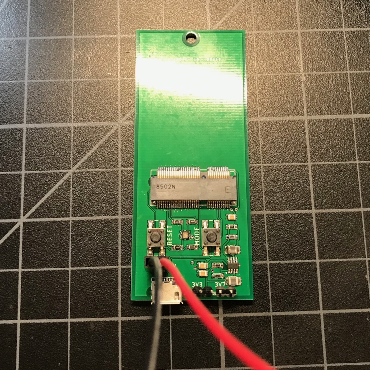
Be careful as even at a few amps, these small switching regulators can get hot enough to melt the solder in seconds in a catastrophic failure scenario.
Assuming the board is not drawing more than 10 mA and does not seem to be catching on fire, on to check the voltage regulator.
Check the voltage on the two indicated pins. The left should be 3.3V and the right should be approximately 3.875V.
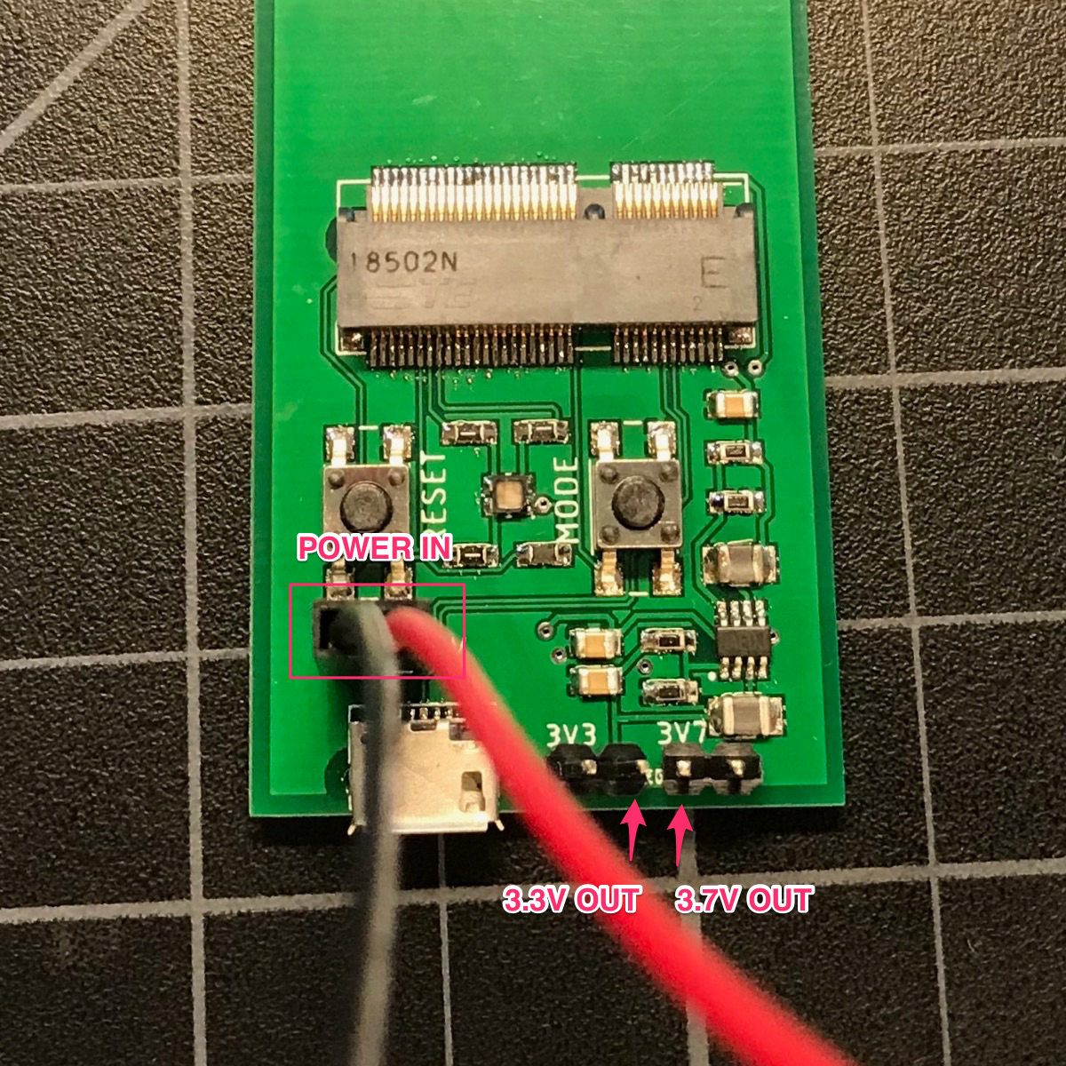
If that checks out, remove the power. Then add two jumpers on 3V3 and 3V8.
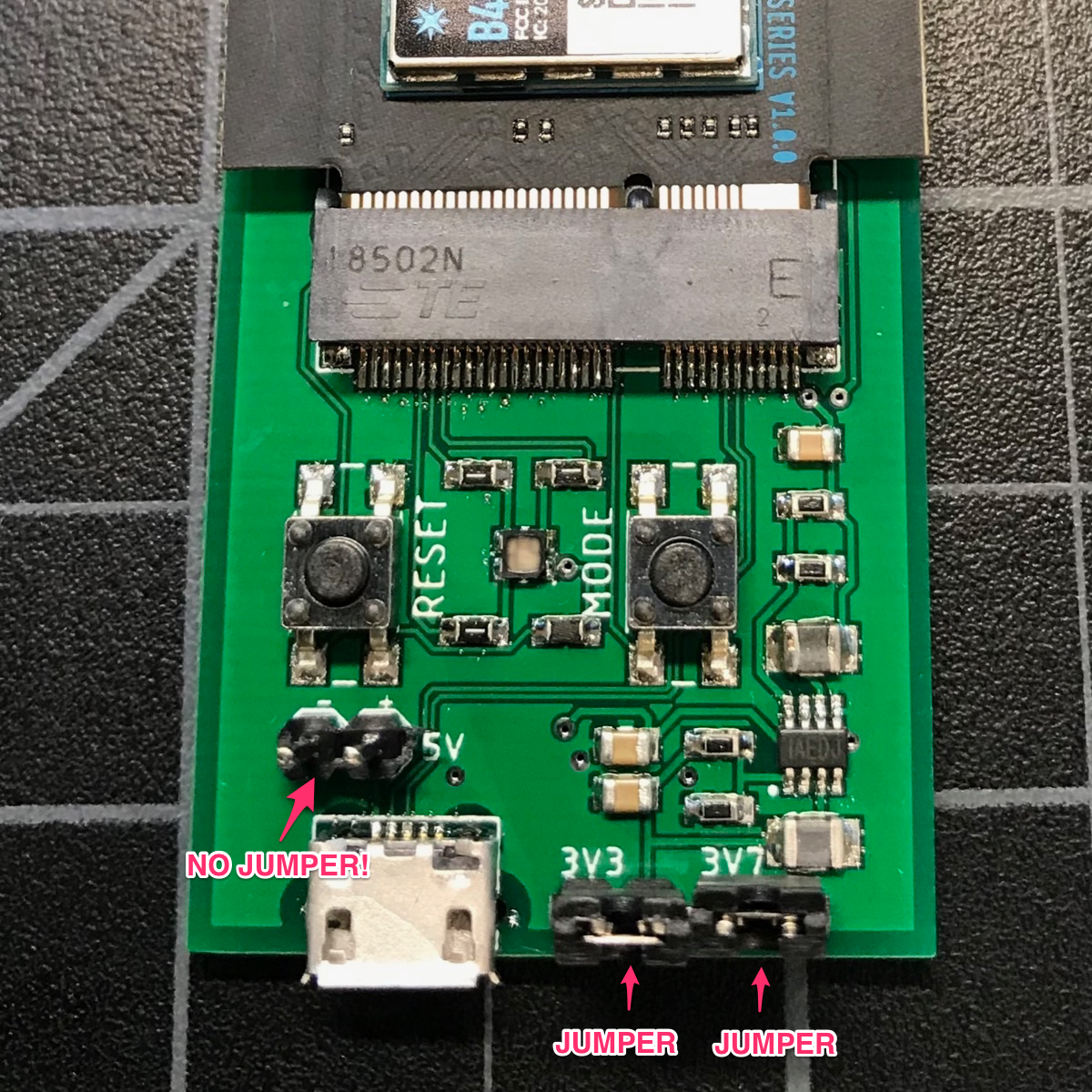
The reason for the jumpers on this particular test board is so you can isolate the power supply if there are issues, also do things like insert an ammeter to measure current. You normally won't add the jumpers on your own boards.
Be sure you don't add a jumper on the 5V! That's the power input and should never have a jumper. Also don't apply 5V and use the USB connector at the same time.
With the two jumpers installed you can now test the power near the M.2 connector.

You can test the LED by connecting the R, G, and B pins to GND.
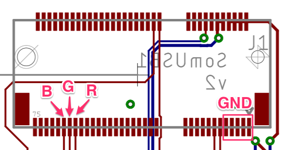
Test USB power. Remove the bench supply and connect the USB to a USB power supply or hub. Check 3V3 and 3V8 and make sure they're good.
Test with the SoM
Now you can test with a SoM! Be sure to use some sort of screw assembly to hold it securely in place. I use a M3 x 6mm screw and nut.


See if the device boots normally and the LED goes through the normal sequence (white, blinking green, blinking cyan, fast blinking cyan, breathing cyan).
Try entering other modes like DFU mode (blinking yellow). With a computer, try listing DFU devices and see if it shows up.
dfu-util -l
Celebrate making your first working SoM base board!
Version history
2024-01-22 (v3)
- M.2 pin 40 should be D3 and M.2 pin 42 should be D2. These were reversed previously, however this sample board does not use the pins.
2020-03-30 (v2)
- Changed R8 from 158K to 150K to change 3V7 to 3V8. The voltage increase to 3.875V adds an extra safety margin for some modem modules.
2019-10-24
- Updated M.2 standoff
2019-05-20
- Initial version
