
Tracker CAN
You can download the files associated with this app note as a zip file.
This application note shows how to use the CAN bus for OBD-II to retrieve engine RPM:
- Setup parameters for CAN bus
- Requesting data via CAN bus
- Parsing CAN response
It also includes a number of techniques that will be useful in many more applications:
- Adding data to location publishes.
- Aggregating data that frequently changes, and upload minimum, average (mean), and maximum with location publishes.
- Adjusting the location publish rate based on criterial (such as when the engine is running faster than idle).
- Using cloud-configurable parameters. In this example, the engine idle speed and frequency to publish when engine is running fast.
This app note uses the Particle CAN library can-mcp25x. The develop version of Tracker Edge firmware and version 9 and later will include this automatically, however you can manually include it in earlier versions if desired.
It is also possible to use MCP_CAN_RK which is a fork of MCP_CAN_lib with some Particle-specific additions. The original version of this application note used that library, and migration instructions are included at the end of this app note.
Since it's a pain to sit in your car with a laptop to experiment with this, there's a design for a simulator in the Simulator directory.
Connecting
- Male J1962 cable ($14.99 for 2)
| Pin | Purpose | Color |
|---|---|---|
| 5 | Signal Ground (optional) | Yellow |
| 6 | CANH | Green |
| 14 | CANL | Brown/White |
Note: There are Green and Green/White and Brown and Brown/White so beware of the white stripe. It's small and easily missed as it's along the length and only on one side.
Note that CAN bus is differential and consists of two lines:
- CANH (high), CAN_P (positive), or CAN+
- CANL (low), CAN_N (negative), or CAN-
As the signals are differential you don't need to connect GND for CAN bus.
Termination resistors
The CAN bus requires termination resistors, typically 120 ohms on each end of the CAN bus to prevent reflection of the signal.
In some cases, you will attach the Tracker One or Tracker SoM in the middle of the CAN bus, so no additional termination will be necessary.
If you are attaching the Tracker to a vehicle OBD-II port, you may not need to add termination as the diagnostic connector may already include termination and be sufficient.
If you are directly connecting another CAN module to the Tracker you will have to add termination resistors on both ends. The Tracker SoM and Tracker One do not contain 120 ohm termination resistors.
Getting the Tracker Edge firmware
You can download a complete project for use with Particle Workbench as a zip file here:
Version:
- Extract tracker-an017.zip in your Downloads directory
- Open the tracker-an017 folder in Workbench using File - Open...; it is a pre-configured project directory.
- From the Command Palette (Command-Shift-P or Ctrl-Shift-P), use Particle: Configure Project for Device.
Manually
The Tracker Edge firmware can be downloaded from GitHub:
https://github.com/particle-iot/tracker-edge
You will probably want to use the command line as there are additional commands you need to run after cloning the source:
git clone https://github.com/particle-iot/tracker-edge
cd tracker-edge
git submodule update --init --recursive
- Open Particle Workbench.
- From the command palette, Particle: Import Project.
- Run Particle: Configure Workspace for Device, select version 2.0.0-rc.3, or later, Tracker, and your device.
- Run Particle: Flash application (local).
Make sure you've used the Mark As Development Device option for your Tracker device in your Tracker product. If you don't mark the device as a development device it will be flashed with the default or locked product firmware version immediately after connecting to the cloud, overwriting the application you just flashed.
CAN support requires Tracker Edge v10 or later, which requires 2.0.0-rc.3 or later.
Full source
Digging in
// Various OBD-II (CAN) constants
const uint8_t SERVICE_CURRENT_DATA = 0x01; // also known as mode 1

// These are the CAN IDs (11-bit) for OBD-II requests to the primary ECU
// and the CAN ID for the response.
const uint32_t OBD_CAN_REQUEST_ID      = 0x7DF;
const uint32_t OBD_CAN_REPLY_ID        = 0x7E8;

// Note: SAE PID codes are 8 bits. Proprietary ones are 16 bits.
const uint8_t PID_ENGINE_RPM          = 0x0C;
const uint8_t PID_VEHICLE_SPEED       = 0x0D;

// This is the request we make by OBD-II. It's always the same and requests the engine RPM.
byte obdRequest[8] = {0x02, SERVICE_CURRENT_DATA, PID_ENGINE_RPM, 0xcc, 0xcc, 0xcc, 0xcc, 0xcc};
This are various parameters specific to using OBD-II to retrieve engine RPM data. If you want to retrieve different data, you'd customize this.
CAN consists of small frames, a maximum of 8 bytes per frame. The data rates vary, typically up to 1 Mbit/sec.. Most vehicles use 500 Kbit/sec for OBD-II. Some use 250 Kbit/sec..
The objRequest is the frame used to request the engine RPM. It's also how you request the vehicle speed by switching to a different PID.
There are several useful articles on Wikipedia:
// How often to request the data by CAN in milliseconds
unsigned long requestLastMillis = 0;
const unsigned long requestPeriod = 100; // in milliseconds (10 times per second)
CAN is always request-response. The engine computer (in the case of OBD-II) does not spontaneously send out information. In this sample, we request the engine RPM 10 times per second. It can go faster than that.
// Various engine stats that we maintain
int lastRPM = 0;
int numSamples = 0;
int offSamples = 0;
int idleSamples = 0;
int nonIdleSamples = 0;
int nonIdleSum = 0;
int nonIdleMin = 0;
int nonIdleMax = 0;
This are the variables we use to accumulate our stats. They're cleared when a location publish is sent out.
We know that the requestPeriod is 100 milliseconds so by keeping track of the number of samples, we know how long we've spent in that state. Specifically:
- How long total (
numSamples) because the publish frequency may vary - How long the engine was off, 0 RPM or CAN not responding (
offSamples) - How long the engine was running at idle speed (
idleSamples) - How long the engine was running at higher speeds (
nonIdleSamples)
We also calculate the minimum non-idle RPM (nonIdleMin) and maximum (nonIdleMax). The average (mean) is calculated by summing the values in nonIdleSum and dividing by nonIdleSamples (if not zero).
// Configuration settings, synchronized with the cloud
int fastPublishPeriod = 0;
int idleRPM = 1600;
These two parameters are cloud configuration parameters. They can be set product-wide or per-device if the device is marked as a development device, as described below.
Not only are they cloud configurable, but the last value is stored in the flash file system, so the last known value can be retrieved before cloud connecting. If the configured value changed while offline, it will be updated automatically after cloud connecting. If the value is changed while online, it's updated immediately, no need to wait to reconnect.
// Object for the CAN library. Note: The Tracker SoM has the CAN chip connected to SPI1 not SPI!
MCP_CAN canInterface(CAN_CS, SPI1);
This is the library interface to the CAN controller chip. Of note:
CAN_CSis the SPI chip selectCAN_INTis the interrupt line- It is connected to
SPI1
// Initialize tracker stuff
Tracker::instance().init();

// Callback to add key press information to the location publish
Tracker::instance().location.regLocGenCallback(myLocationGenerationCallback);
Initialize the Tracker Edge library and register a callback function to be called to add information to location publishes.
// Set up configuration settings
static ConfigObject engineDesc("engine", {
    ConfigInt("idle", &idleRPM, 0, 10000),
    ConfigInt("fastpub", &fastPublishPeriod, 0, 3600000),
});
Tracker::instance().configService.registerModule(engineDesc);
This is how you connect variables (idleRPM and fastPublishPeriod) to the configuration service. You specify a top level key and any sub-keys.
For the idle key, we save the integer value in idleRPM with a range of 0-10000.
For the fastpub key, we save the integer value in fastPublishPeriod with a range of 0-3600000. 0 means don't speed up publishing; use the configuration defaults for the product or device (such as time, radius, etc..).
This is what the JSON configuration object looks like:
{
    "engine":{
        "idle":1600,
        "fastpub":30000
    }
}
When this is loaded from the flash file system or sent from the configuration service, the variables are updated automatically.
// Turn on CAN_5V power
pinMode(CAN_PWR, OUTPUT);
digitalWrite(CAN_PWR, HIGH);

// Set STBY low to enable transmitter and high-speed receiver
pinMode(CAN_STBY, OUTPUT);
digitalWrite(CAN_STBY, LOW);

// Enable the CAN interrupt pin as an input just in case
pinMode(CAN_INT, INPUT);

// Hardware reset the CAN controller. Not really necessary, but doesn't hurt.
pinMode(CAN_RST, OUTPUT);
digitalWrite(CAN_RST, LOW);
delay(100);
digitalWrite(CAN_RST, HIGH);
This is the setup when using CAN. Make sure you set CAN_PWR and CAN_STBY to the correct state!
// Most vehicles use 500 kbit/sec for OBD-II
// Make sure the last parameter is MCP_20MHZ; this is dependent on the crystal
// connected to the CAN chip and it's 20 MHz on the Tracker SoM.
byte status = canInterface.begin(MCP_SIDL, CAN_500KBPS, MCP_20MHZ);
if(status == CAN_OK) {
    Log.info("CAN initialization succeeded");
}
else {
    Log.error("CAN initialization failed %d", status);
}
You occasionally need to change the CAN bus speed (for example to CAN_250KBPS), but make sure you leave the last parameter as MCP_20MHZ. That speed is determined by the crystal connected to the interface chip on the Tracker SoM.
If you were making a real product, you might even make the CAN bus speed a cloud configurable parameter.
// Change to normal mode to allow messages to be transmitted. If you don't do this,
// the CAN chip will be in loopback mode.
canInterface.setMode(MCP_MODE_NORMAL);
Make sure you always set the CAN mode to MCP_MODE_NORMAL, otherwise it will stay in loopback mode and not send any data to other devices!
// Must call this on every loop
Tracker::instance().loop();
Make sure you call Tracker::instance().loop() on every call to loop().
// Handle received CAN data
if (!digitalRead(CAN_INT)) {
    long unsigned int rxId;
    unsigned char len = 0;
    unsigned char rxBuf[8];

    canInterface.readMsgBufID(&rxId, &len, rxBuf);      // Read data: len = data length, buf = data byte(s)

    if ((rxId & 0x80000000) == 0x00000000) {
        // Standard frame

        // Log.info("%.3lx: %02x %02x %02x %02x %02x %02x ", rxId, rxBuf[0], rxBuf[1], rxBuf[2], rxBuf[3], rxBuf[4],rxBuf[5]  );
        if (rxId == OBD_CAN_REPLY_ID && rxBuf[0] == 0x04 && rxBuf[1] == 0x41 && rxBuf[2] == PID_ENGINE_RPM) {
            lastRPM = (rxBuf[3] << 8) | rxBuf[4];
            lastRPM /= 4;

            // Log.info("rpm=%d", lastRPM);

            // We don't process the RPM here, it's done below (with an explanation why)
        }
    }

}
This is how you receive data via CAN. Note that you will typically only receive data when you request it, and the request code is below.
When reading the CAN_INT GPIO and the signal is LOW, digitalRead(CAN_INT) returns false, there's data waiting.
CAN data is never longer than 8 bytes to we can easily fit the data in a stack-based variable (rxBuf).
canInterface.readMsgBufID(&rxId, &len, rxBuf); // Read data: len = data length, buf = data byte(s)
This does the actual read from the CAN bus queue.
if (rxId == OBD_CAN_REPLY_ID && rxBuf[0] == 0x04 && rxBuf[1] == 0x41 && rxBuf[2] == PID_ENGINE_RPM)
This checks to see if this is the data we are expecting:
rxId == OBD_CAN_REPLY_IDfor a reply to our requestrxBuf[0]is the length, and the engine RPM reply is 4 bytes (always)rxBuf[1]is the 0x41, which is the code for response toSERVICE_CURRENT_DATA. It's that becauseSERVICE_CURRENT_DATAis 0x01, and the response adds 0x40 to make the response code.
lastRPM = (rxBuf[3] << 8) | rxBuf[4];
lastRPM /= 4;
The RPM data is big-endian 16-bit (MSB first in byte rxBuf[3], LSB in rxBuf[4]).
The unit is quarter of an RPM, so we divide by 4 and ignore the fractional part rather than using a float here.
if (millis() - requestLastMillis >= requestPeriod) {
    requestLastMillis = millis();
This block of code is executed 10 times per second as requestPeriod is 100 milliseconds. Note that when you structure a test for millis() exactly like this it works correctly even when millis() rolls over back to 0 every 49 days.
// Log the last RPM information. We do this here because it simplifies the logic
// for when the send failed (vehicle off)
numSamples++;
if (lastRPM == 0) {
    // Engine was off or send failed
    offSamples++;
}
else
if (lastRPM < idleRPM) {
    // The engine is idling, store that as a separate counter
    idleSamples++;
}
else {
    // Engine was faster than idle. Note the min, max, and mean.
    nonIdleSamples++;
    nonIdleSum += lastRPM;

    if (lastRPM < nonIdleMin || nonIdleMin == 0) {
        nonIdleMin = lastRPM;
    }
    if (lastRPM > nonIdleMax) {
        nonIdleMax = lastRPM;
    }
}
This is just how we calculate the samples. Note that we do it here, in the every 10 milliseconds test, rather than inside the CAN response handler. This allows the code to work even when a request fails (such as vehicle turned off).
// Send a request for engine RPM via OBD-II (CAN)
byte sndStat = canInterface.sendMsgBuf(OBD_CAN_REQUEST_ID, 0, 8, obdRequest);
if(sndStat == CAN_OK) {
    errorFlag = false;
}
else {
    if (!errorFlag) {
        Log.error("Error Sending Message %d", sndStat);
        errorFlag = true;
    }
}
This is where we send the request out over the CAN bus. obdRequest is a static buffer as the request is the same on every call.
// Print engine info to the serial log to help with debugging
if (engineLogPeriod != 0 && millis() - lastEngineLog >= engineLogPeriod) {
    lastEngineLog = millis();

    int nonIdleMean = nonIdleSamples ? (nonIdleSum / nonIdleSamples) : 0;

    Log.info("engineOff=%d engineIdle=%d engineNonIdle=%d engineMin=%d engineMean=%d engine<Max=%d",
        (int)(offSamples * requestPeriod / 1000),
        (int)(idleSamples * requestPeriod / 1000),
        (int)(nonIdleSamples * requestPeriod / 1000),
        nonIdleMin, nonIdleMean, nonIdleMax
    );
}
Publishes don't happen that often, but we don't want to log to debug serial on every request as that happens so frequently the logs get unruly. This prints out some information every 2 seconds, which is more manageable.
if (Particle.connected() && lastRPM >= idleRPM) {
    // If connected to the cloud and not off or at idle speed, we may want to speed up
    // publishing. This is done by settings engine.fastpub (integer) to a non-zero
    // value, the number of milliseconds between publishes.
    if (fastPublishPeriod > 0 && millis() - lastFastPublish >= (unsigned long) fastPublishPeriod) {
        lastFastPublish = millis();

        Log.info("manual publish lastRPM=%d idleRPM=%d period=%d", lastRPM, idleRPM, fastPublishPeriod);
        Tracker::instance().location.triggerLocPub();
    }
}
When cloud connected and engine above idle speed, we do some extra stuff:
If the fastPublishPeriod is non-zero and that time period has expired, do a manual location publish. This is how you:
- Can boost publish speed on certain on-device criteria (cloud connected and RPM)
- Period is cloud-configured, not part of the user firmware, so you can reset it easily.
Setting cloud configuration
The configuration data that is sent between the device and cloud is described by a schema. Not only does this define valid values for the fields, but it also describes the presentation of the data in the console user interface. You can add new elements to the schema and you can edit the values of your custom fields directly from the console!
Setting a custom schema
These are the fields that will be added. This not only describe the data, but match the configuration data in the user firmware, and are also used to describe the console user interface.
The easiest way to set the schema is using the control here.
| Product | |
| Device | |
You can also set the schema manually using curl:
curl -X PUT 'https://api.particle.io/v1/products/:productId/config/:deviceId' -H "Authorization: Bearer :access_token" -H 'Content-Type: application/schema+json' -d @engine-schema.json
Be sure to update:
:productIdwith your product ID:deviceIdwith your Device ID that is set as a development device. If you want to change the setting across your whole product leave off the slash and device ID.:accessTokenwith a product access token, described above.
To remove the Engine panel and restore the default schema use the Restore Default Schema button:
Using the console
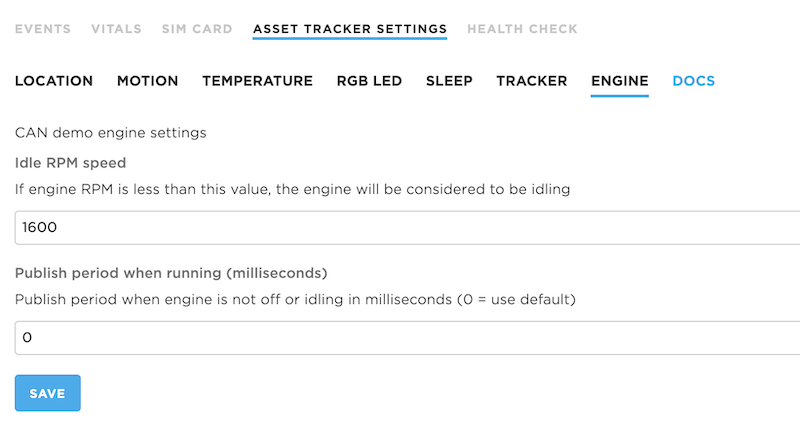
With the schema set, you can now go into configuration (either device or product-wide, depending on what you set), and there will be a new tab, ENGINE!
There is a pretty obvious mapping from the JSON above to the fields in the console. And you can now manipulate the engine settings from the console.
Setting values using the API
You can also set the values using the API directly, such as by using curl:
curl -X PUT 'https://api.particle.io/v1/products/:productId/config/:deviceId' -H "Authorization: Bearer :access_token" -H "Content-Type: application/json" -d "{\"engine\":{\"idle\":1550,\"fastpub\":30000}}"
Be sure to update:
:productIdwith your product ID:deviceIdwith your Device ID that is set as a development device. If you want to change the setting across your whole product leave off the slash and device ID.:accessTokenwith a product access token, described above.
This sets this configuration object:
{
    "engine":{
        "idle":1550,
        "fastpub":30000
    }
}
If successful and the device is online, you should see something like:
{"message":"The device has been updated"}
And if you are monitoring the USB debug serial on the device, you should see something like:
0000398762 [app] INFO: cloud received: {"cmd":"set_cfg","cfg":{"engine":{"idle":1550,"fastpub":30000}}}
0000398764 [app] INFO: manual publish lastRPM=4987 period=30000
0000399000 [app] INFO: cloud sent: {"cmd":"cfg","time":1595260557,"cfg":{"engine":{"idle":1550,"fastpub":30000}}}
0000399003 [app] INFO: saving config engine: {"version":1,"hash":"22C59270DD3925B37E24D4657E24D465","engine":{"idle":1550,"fastpub":30000}}
0000400296 [app] INFO: cloud received: {"cmd":"ack","req_id":3,"src_cmd":"loc","status":0}
0000400672 [app] INFO: engineOff=0 engineIdle=0 engineNonIdle=0 engineMin=4987 engineMean=4989 engine<Max=4991
Migrating from MCP_CAN_RK
The original version of this library used MCP_CAN_RK which is a fork of MCP_CAN_lib with some Particle-specific additions. If you used this library and want to migrate to the official can-mcp25x library you'll need to make a few minor source changes:
MCP_CAN Constructor
The MCP_CAN_RK library takes a pointer to the SPI interface. Change to a reference:
Before:
MCP_CAN canInterface(CAN_CS, &SPI1);
After:
MCP_CAN canInterface(CAN_CS, SPI1);
mcp.begin constants like MCP_STD and MCP_ANY
Before:
byte status = canInterface.begin(MCP_STD, CAN_500KBPS, MCP_20MHZ);
After:
byte status = canInterface.begin(MCP_SIDL, CAN_500KBPS, MCP_20MHZ);
| Before | After | Numeric |
|---|---|---|
| MCP_STDEXT | MCP_SIDH | 0 |
| MCP_STD | MCP_SIDL | 1 |
| MCP_EXT | MCP_EID8 | 2 |
| MCP_ANY | MCP_EID0 | 3 |
setMode values
Before:
canInterface.setMode(MCP_NORMAL);
After:
canInterface.setMode(MCP_MODE_NORMAL);
| Before | After | Numeric |
|---|---|---|
| MCP_NORMAL | MCP_MODE_NORMAL | 0x00 |
| MCP_SLEEP | MCP_MODE_SLEEP | 0x20 |
| MCP_LOOPBACK | MCP_MODE_LOOPBACK | 0x40 |
| MCP_LISTENONLY | MCP_MODE_LISTENONLY | 0x60 |
readMsgBuf
Calls to readMsgBuf() must be changed to readMsgBufID().
Before:
canInterface.readMsgBuf(&rxId, &len, rxBuf)
After:
canInterface.readMsgBufID(&rxId, &len, rxBuf)