
Tracker keypad LCD
You can download the files associated with this app note as a zip file.
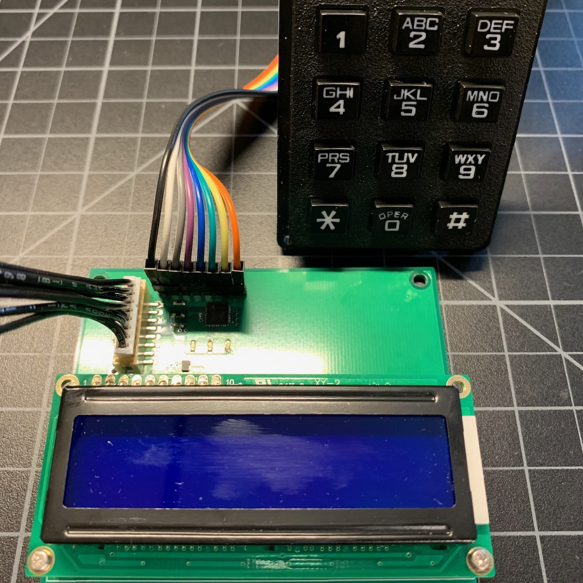
This project demonstrates adding a keypad, LCD character display, DAC, and cloud configuration to the Tracker One using the M8 connector. You probably wouldn't build one of these as is, as it's just a demonstration board, but it is an example of the kinds of things you can add using the M8 connector.
- Using a MAX7360 to read matrix keypads and drive LEDs
- Using a character LCD display with an I2C interface
- Interfacing to 5V I2C devices
- Using an I2C DAC (digital to analog converter), used to handle the contrast for the LCD
- Implementing cloud-configurable settings (contrast)
- Adding data to location events (keypad digits)
- Showing GNSS lock and cloud connection status with custom LEDs
Connecting
The M8 (8mm) 8-pin connector on the Tracker One is standard, however it's not common. Some other connectors like M12 are more common, however, the 12mm connector would have required a taller enclosure to fit the larger connector. To simplify designs, Particle will provide a M8 female-to-wires cable, similar to this. This is for illustration only and the design may vary in the future.
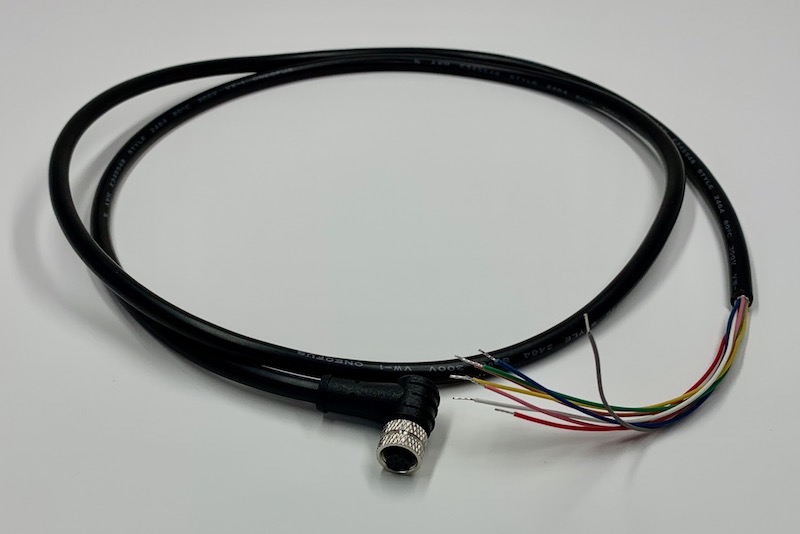
The common use case will be to include a cable gland in your expansion enclosure, pass the wires through the gland, and terminate them on your custom expansion board.
You'd typically connect those wires to your custom expansion board using one of several methods:
- Terminate with pins in a PHR-8 to mate with a B8B-PH on your expansion board
- Terminate with screw terminals on your board
- Terminate by soldering the wires to your board
This example can be used three different ways:
It can use the same B8B-PH connector that is inside the Tracker One on the Tracker Carrier board. This connector is inexpensive and can be attached directly to the Tracker One Carrier Board.
Or you can populate a 8x0.1" screw terminal header. This is good for connecting to the M8 to flying leads.
Or you can populate 0.1" male header pins, which are handy for use with male-to-female Dupont wires for connecting directly to the Tracker SoM evaluation board.
Hardware
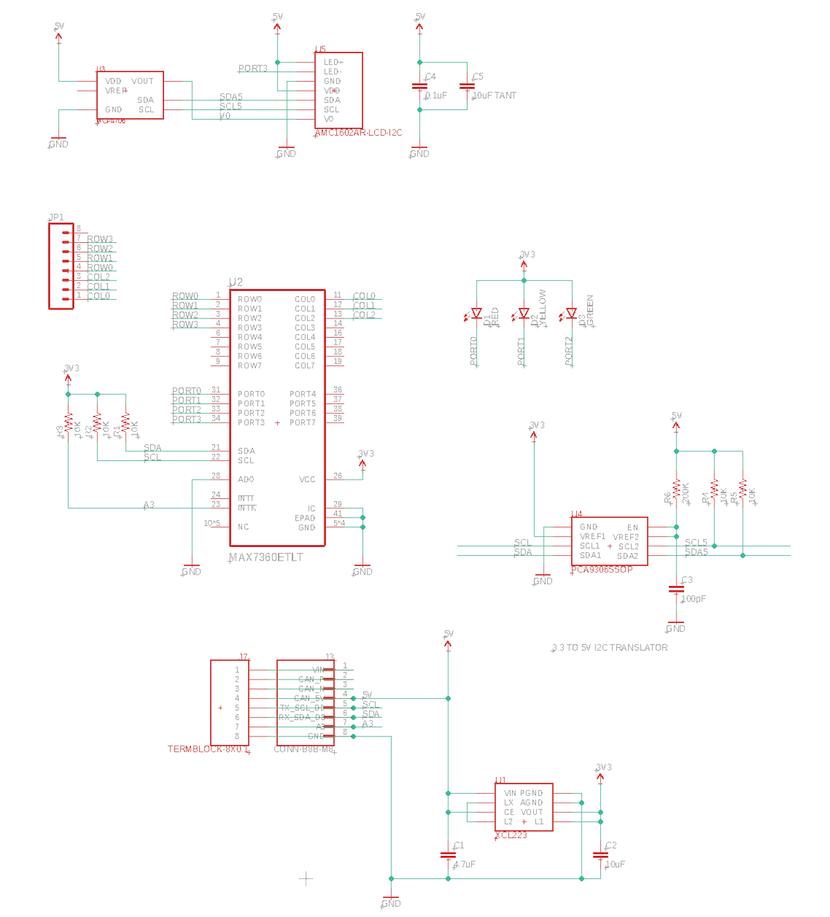
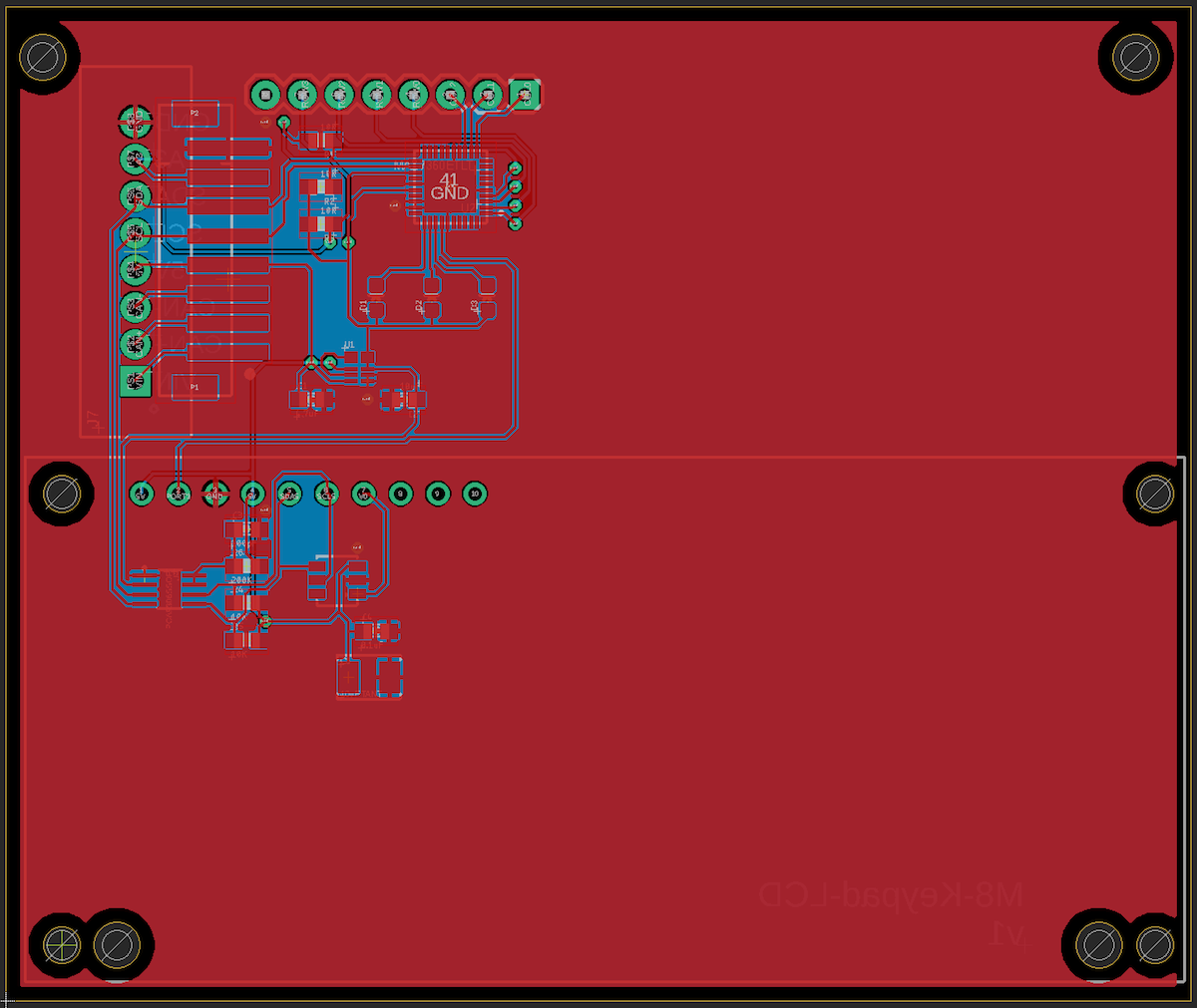
Schematic and board
Power and M8 connection
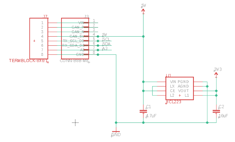
This board is intended to be powered by the M8 connector, which includes the 5V CAN_PWR. This is a controllable boost power supply that supplies 5V at 370 mA even off battery.
Since much of the logic including the nRF52840 GPIO and I2C run only at 3.3V, a 3.3V regulator (XCL224) is included in this design. This regulator is a tiny switching regulator and is nice because it does not require an external inductor, saving space and cost.
MAX7360
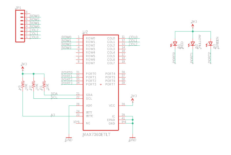
The MAX7360 is a super-useful keypad, GPIO expander, and LED driver with an I2C interface. The chip is tiny (40TQFN) and a bit expensive ($5.22), but it can do a lot:
- Support for passive matrix keypads up to 8x8. It's perfect for 3x4 phone-style keypads and 4x4 small keypads.
- Built-in debounce (with programmable delay) and FIFO queue for keypad press and release.
- 8 GPIO pins with PWM support.
- Built-in constant-current driver so you don't need current-limiting resistors for LEDs.
- Additional open-drain output ports if you're not using all of the columns.
- Built-in support for LED blink and fade in or out.
- Individual PWM control for up to 8 LEDs.
- Rotary encoder support.
- Debounce support for switches attached to GPIO with programmable delay.
- I2C interface. Addressing support for up to 4 MAX7360 on a single I2C bus.
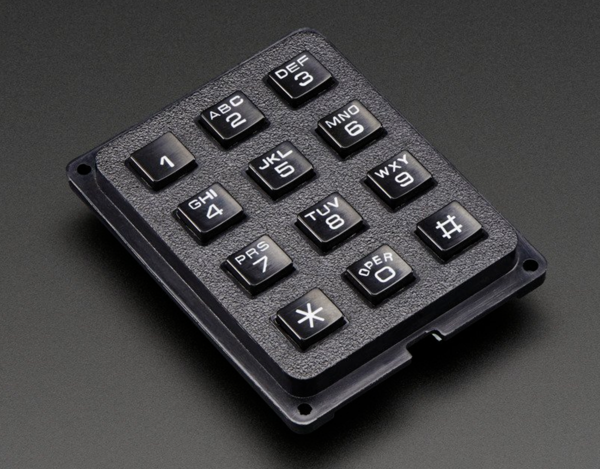
I use a 3x4 phone matrix keypad in this example. It's a completely passive keypad. One of the advantages of using it with the MAX7306 is that the MAX7306 handles debounce and queueing of keys in hardware so you can press buttons as fast as you want and presses won't be lost even if the MCU is busy.
There are also three LEDs in this design: red, yellow, and green connected to PORT0 - PORT3. One of the nice things about the MAX7360 is that it can directly drive LEDs as it has a built-in constant current source (programmable), PWM, and even supports blink and fade in hardware. These LEDs are 5 mA SMD 0603 LEDs.
Display and DAC
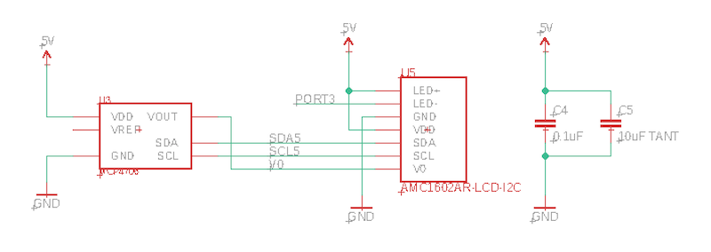
The LCD display is a Orient Display AMC1602AR-B-B6WTDW-I2C ($7.49). It's 16 column x 2 line character LCD display with a 5V I2C interface, 80mm x 36mm. Power consumption is 1.2 mA (typical) plus 30 mA for the backlight at 5V.
The advantage of the character LCDs is much lower code flash and RAM usage than bitmap displays like the SSD1306.
Displays of this type need a contrast control voltage from 0-5V. Normally a potentiometer is used, but I added a Microchip Technology MCP4706A0T-E/CH. It's an inexpensive ($0.71) 8-bit DAC in a tiny SOT-23-6 package.
As a further illustration, the contrast is cloud-configurable!
Level shifter
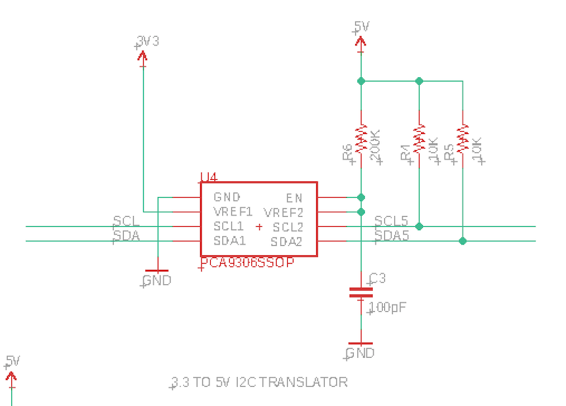
This example uses both 3.3V and 5V I2C. The nRF52840 and MAX7360 both require 3.3V I2C. However the LCD display and DAC require 5V. A PCA9306 I2C level shifter is used.
Since I2C is bidirectional on both SDA and SCL, you can't just use a simple level shifter.
BoM (Bill of Materials)
| Quantity | Part | Description | Example | Cost |
|---|---|---|---|---|
| 1 | C1 | Capacitor Ceramic 4.7uF 6.3V 0603 | Murata GRM188R60J475KE19J | |
| 1 | C2 | Capacitor Ceramic 10uF 16V 0805 | Murata GRM21BR61C106KE15L | |
| 1 | C3 | Capacitor Ceramic 100pF 50V 0603 | Kemet C0603C101J5GACTU | |
| 1 | C4 | Capacitor Ceramic 0.1uF 0603 | Panasonic GRM188R71C104KA01D | |
| 1 | C5 | Capacitor Tantalum 10 uF | Murata GRM21BR61C106KE15L | $0.21 |
| 5 | R1-R5 | Resistor 10K 5% 1/4W 0603 | Panasonic ERJ-PA3J103V | |
| 1 | R6 | Resistor 200K 1% 1/10W 0603 | Panasonic ERJ-3EKF2003V | |
| 1 | U1 | XCL224 3.3V regulator | Torex XCL224A333D2-G | $ 2.43 |
| 1 | U2 | MAX7360 IC CTRLR KEY-SW I2C 40TQFN | MAX7360ETL-T | $5.22 |
| 1 | U3 | 8-bit I2C DAC | Microchip MCP4706A0T-E/CH | $ 0.71 |
| 1 | U4 | PCA9306SSOP | TI | $0.67 |
| 1 | U5 | LCD display 16x2 I2C | Orient Display AMC1602AR-B-B6WTDW-I2C | $7.49 |
| 1 | U5 | 10-pin female header PTH | Sullins PPTC101LFBN-RC | $0.65 |
| 1 | D1 | Red LED 5mA 0603 | Lite-On LTST-C193KRKT-5A | $0.41 |
| 1 | D2 | Yellow LED 5mA 0603 | Lite-On LTST-C193KSKT-5A | $0.41 |
| 1 | D3 | Green LED 5mA 0603 | Lite-On LTST-C193KGKT-5A | $0.41 |
| 1 | 3x4 Matrix Keypad | Adafruit 1824 | $7.50 |
Choose one of:
| Quantity | Part | Description | Example | Cost |
|---|---|---|---|---|
| 1 | J3 | Conn SMD 8 position 2.00mm | JST B8B-PH-SM4-TB(LF)(SN) | $1.00 |
| 1 | J7 | Male Header Pins (8x0.1") | Sullins PRPC040SAAN-RC | |
| 1 | J7 | Screw Terminal Block 8x0.1" PTH | On Shore OSTVN08A150 | $2.36 |
Firmware
Firmware features
LEDs
- The red LED (left) indicates the GNSS fix/lock status. When lit, there is a GNSS lock.
- The yellow LED (middle) is not currently used
- The green LED (right) indicates the cloud connection status. When lit, the device is cloud connected.
Display
- The top line of the LCD display shows your GNSS coordinates (when there is a lock).
- The bottom line of the LCD display shows the digits you typed on the keypad.
- The display contrast can be set from the cloud.
Keypad
When you press buttons on the keypad the second line of the display will update. On the next location publish they are included in the keys within the location event. These show up in the Custom Data section in the console.
After 5 seconds of no button pressing, the next time you press a digit the keys will be cleared so you can start over with new digits.
Getting the Tracker Edge firmware
You can download a complete project for use with Particle Workbench as a zip file here:
Version:
- Extract tracker-an016.zip in your Downloads directory
- Open the tracker-an016 folder in Workbench using File - Open...; it is a pre-configured project directory.
- From the Command Palette (Command-Shift-P or Ctrl-Shift-P), use Particle: Configure Project for Device.
- If you are building in the cloud, you can use Particle: Cloud Flash or Particle: Cloud Compile.
- If you are building locally, open a CLI window using Particle: Launch CLI then:
particle library copy
Manually
The Tracker Edge firmware can be downloaded from GitHub:
https://github.com/particle-iot/tracker-edge
You will probably want to use the command line as there are additional commands you need to run after cloning the source:
git clone https://github.com/particle-iot/tracker-edge
cd tracker-edge
git submodule update --init --recursive
- Open Particle Workbench.
- From the command palette, Particle: Import Project.
- Run Particle: Configure Workspace for Device, select version 1.5.4-rc.1, 2.0.0-rc.3, or later, Tracker, and your device.
- Run Particle: Flash application (local).
Make sure you've used the Mark As Development Device option for your Tracker device in your Tracker product. If you don't mark the device as a development device it will be flashed with the default or locked product firmware version immediately after connecting to the cloud, overwriting the application you just flashed.
Add the libraries
From the command palette in Workbench, Particle: Install Library then enter MAX7360-RK. Repeat for MAX47x6-RK and AMCLCD-RK.
If you prefer to edit project.properties directly, add these:
The full source
Explanation
#include "MAX7360-RK.h"
#include "MAX47x6-RK.h"
#include "AMCLCD-RK.h"
These are the three additional libraries needed for the three I2C devices used in this example. They are the keyboard/LED controller (MAX7360), DAC for contrast control (MAX4706), and character LCD driver (AMCLCD).
// MAX7360 Keypad and LCD driver, connected by I2C
MAX7360 keyDriver(0x38, Wire3);
MAX7360KeyMappingPhone keyMapper;

// MAX4706 DAC for contrast control
MAX47x6 dac(MAX47x6::Model::MAX4706, 0x60, Wire3);

// Orient Displays AMC1602 16x2 character LCD connected by I2C
AMCLCD_Model_AMC1602 lcdModel;
AMCLCD lcd(lcdModel, 0x3C, Wire3);
Initialization of the I2C devices and libraries.
// Turn on CAN power
pinMode(CAN_PWR, OUTPUT);
digitalWrite(CAN_PWR, HIGH);
This board is powered by the CAN_5V on the M8 connector. It must be turned on, as it defaults to off.
// Set up configuration settings
static ConfigObject contrastDesc("lcdkeypad", {
    ConfigInt("contrast", &contrast, 0, 255),
});
Tracker::instance().configService.registerModule(contrastDesc);
This adds new settings to the configuration manager. The registers a new object lcdkeypad that contains a key/value pair of contrast and an integer in the range of 0-255. When the configuration is sent, it might looks like this in JSON:
{
    "lcdkeypad":{
        "contrast":24
    }
}
// Callback to add key press information to the location publish
Tracker::instance().location.regLocGenCallback(myLocationGenerationCallback);
This adds a location generation callback. This is how we add the keys to the location publishes.
MAX7360Key key = keyDriver.readKeyFIFO();
if (!key.isEmpty()) {
    Log.info("rawKey=0x%02x readable=%c", key.getRawKey(), key.getMappedKey());
In loop() we check the key FIFO on the MAX7360 to see if a key has been pressed. If it has, it's added to the display.
memset(gnssBuf, ' ', sizeof(gnssBuf) - 1);

LocationPoint point;

Tracker::instance().locationService.getLocation(point);
if (point.locked) {
    snprintf(gnssBuf, sizeof(gnssBuf), "%.4f,%.4f", point.latitude, point.longitude);
}

lcd.setPosition(0, 0);
lcd.print(gnssBuf);
This block of code gets the current location from the GNSS, and if locked, updates the LCD display with the new coordinates. If there is no lock, the top display line is cleared, removing the old location (if any).
LocationStatus locStatus;
Tracker::instance().locationService.getStatus(locStatus);
if (wasGnssLocked != locStatus.locked) {
    wasGnssLocked = locStatus.locked;
    keyDriver.setPortPwmRatio(PORT_LED_RED, wasGnssLocked ? 255 : 0);
}
When the fix status changes, we turn the red LED on or off.
if (lastContrast != contrast) {
    Log.info("contrast updated to %d", contrast);
    lastContrast = contrast;
    dac.updateSettings(MAX47x6::VREF_VDD, MAX47x6::GAIN_1X, (uint8_t)contrast, false);
}
If the contrast changes from the cloud, update the DAC to set the new value
void myLocationGenerationCallback(JSONWriter &writer, LocationPoint &point, const void *context)
{
    // keyBuf is always 16 characters long filled with spaces and null terminated for updating the LCD.
    // Make a copy of it so the string will only contain the keys with no trailing spaces.
    char keysCopy[sizeof(keyBuf)];
    strcpy(keysCopy, keyBuf);
    char *cp = strchr(keysCopy, ' ');
    if (cp) {
        *cp = 0;
    }
    writer.name("keys").value(keysCopy);
}
Append the current keys that have been pressed to the location event. This is what's on the second line of the display, without the trailing spaces.
Cloud configuration
The cloud configuration cannot be set from the console, but you can set it from the CLI using curl.
curl -X PUT https://api.particle.io/v1/products/:productId/config/:deviceId -H "Authorization: Bearer :access_token" -H "Content-Type: application/json" -d "{\"lcdkeypad\":{\"contrast\":10}}"
Be sure to update:
:productId with your product ID
:deviceId with your Device ID that is set as a development device. If you want to change the contrast across your whole product leave off the slash and device ID.
:accessToken with a product access token. An easy way to get a temporary
One easy way to get a temporary access token is to:
- Open the console.
- Open your Tracker product.
- Click on Devices.
- Open your device.
- In the Events tab, click on View events from a terminal (it's a button).
- Copy and paste the access token from the end of the command that is displayed.
- This token is invalidated when your close the console.
This sets the lcdkeypad configuration object with a key/value pair of contrast and a value of 10.
If you monitor the USB serial log while you execute that command, you'll see something like::
0000027000 [app] INFO: cloud sent: {"cmd":"cfg","time":1595242046,"cfg":{"lcdkeypad":{"contrast":10}}}
0000027003 [app] INFO: saving config lcdkeypad: {"version":1,"hash":"93D3A4F5AB7167C594B14FDEE70D0FF7","lcdkeypad":{"contrast":10}}
0000027214 [comm.protocol] TRACE: Reply recieved: type=2, code=0
0000027216 [comm.protocol] TRACE: message id 249 complete with code 0.00
0000027218 [comm.protocol] TRACE: rcv'd message type=13
0000028000 [app] INFO: saving config lcdkeypad: {"version":1,"hash":"0C700355869AF65B6BE3CB82B278CB83","lcdkeypad":{"contrast":10}}
0000044208 [comm.protocol] TRACE: rcv'd message type=2
0000044208 [app] INFO: cloud received: {"cmd":"set_cfg","cfg":{"lcdkeypad":{"contrast":10}}}
0000044213 [app] INFO: contrast updated
If you reset the device, you can see the saved configuration value get loaded during Tracker initialization:
0000002075 [app] INFO: loading config lcdkeypad: {"version":1,"hash":"93D3A4F5AB7167C594B14FDEE70D0FF7","lcdkeypad":{"contrast":10}}
If you change the cloud configuration while the device is offline, it will get the updated configuration sent to it when it reconnects to the cloud.