
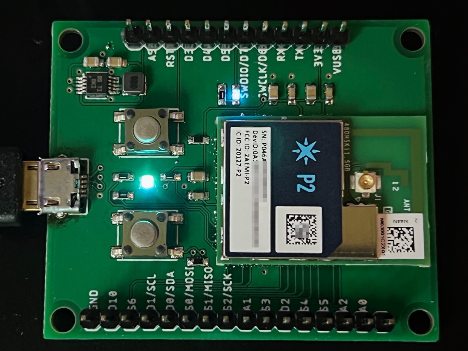
P2 First Board
This tutorial will guide you through some things that may help in making your first P2 base board design.
This board includes basic features needed for P2 designs, including:
- USB connector
- RGB status LED
- RESET and MODE buttons
- Voltage regulator
- Breakout pins for GPIO and ports
Another option is the P2 reference design which is a full breakout board with additional Feather sockets that are compatible with the Photon 2.
Note:
First board and basic design examples are intended to be easily hand-assembled on inexpensive 2-layer circuit boards using easily available parts. They are not intended to be reference examples of best practices for electronic design.
Basic design
The P2 base board in this tutorial is about as simple as you can build. It does not have a fuel gauge or PMIC, and is powered by USB only, with no battery support. There will be other tutorials for more complex power supply designs.
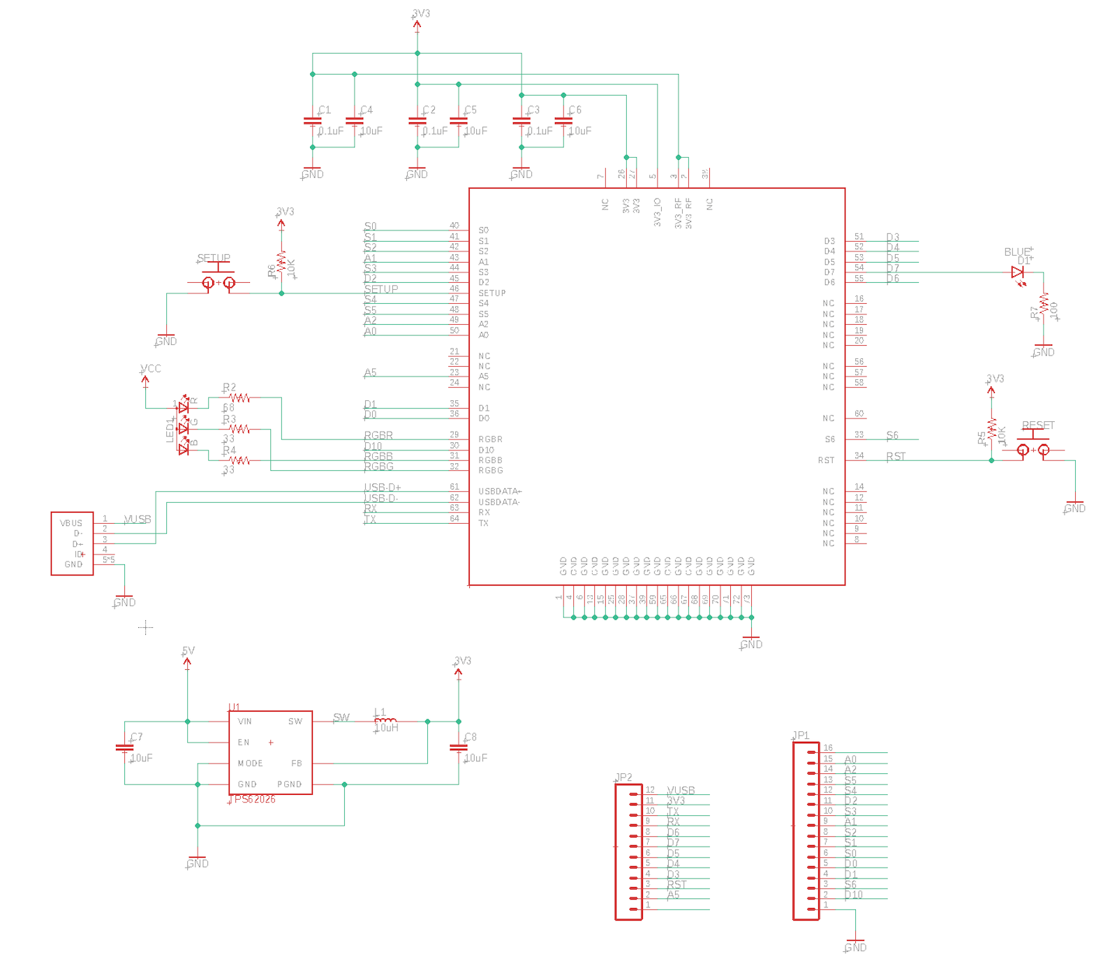
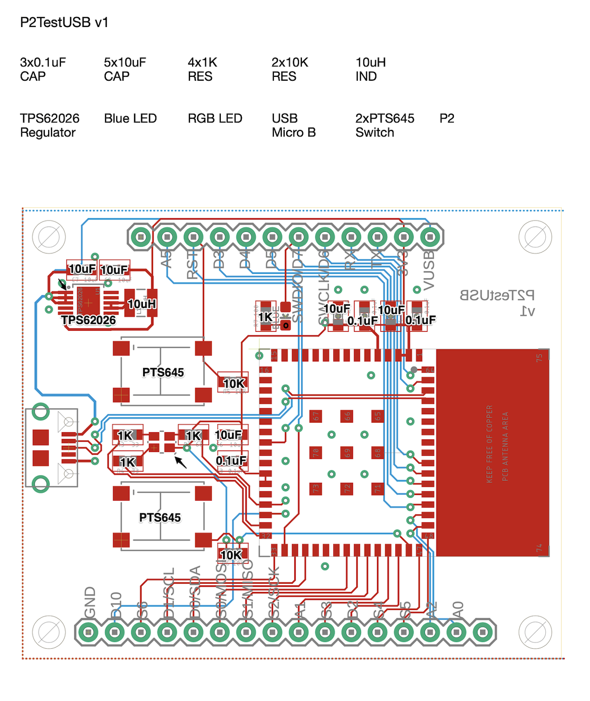
This is the Eagle board design for the USB SoM base board:
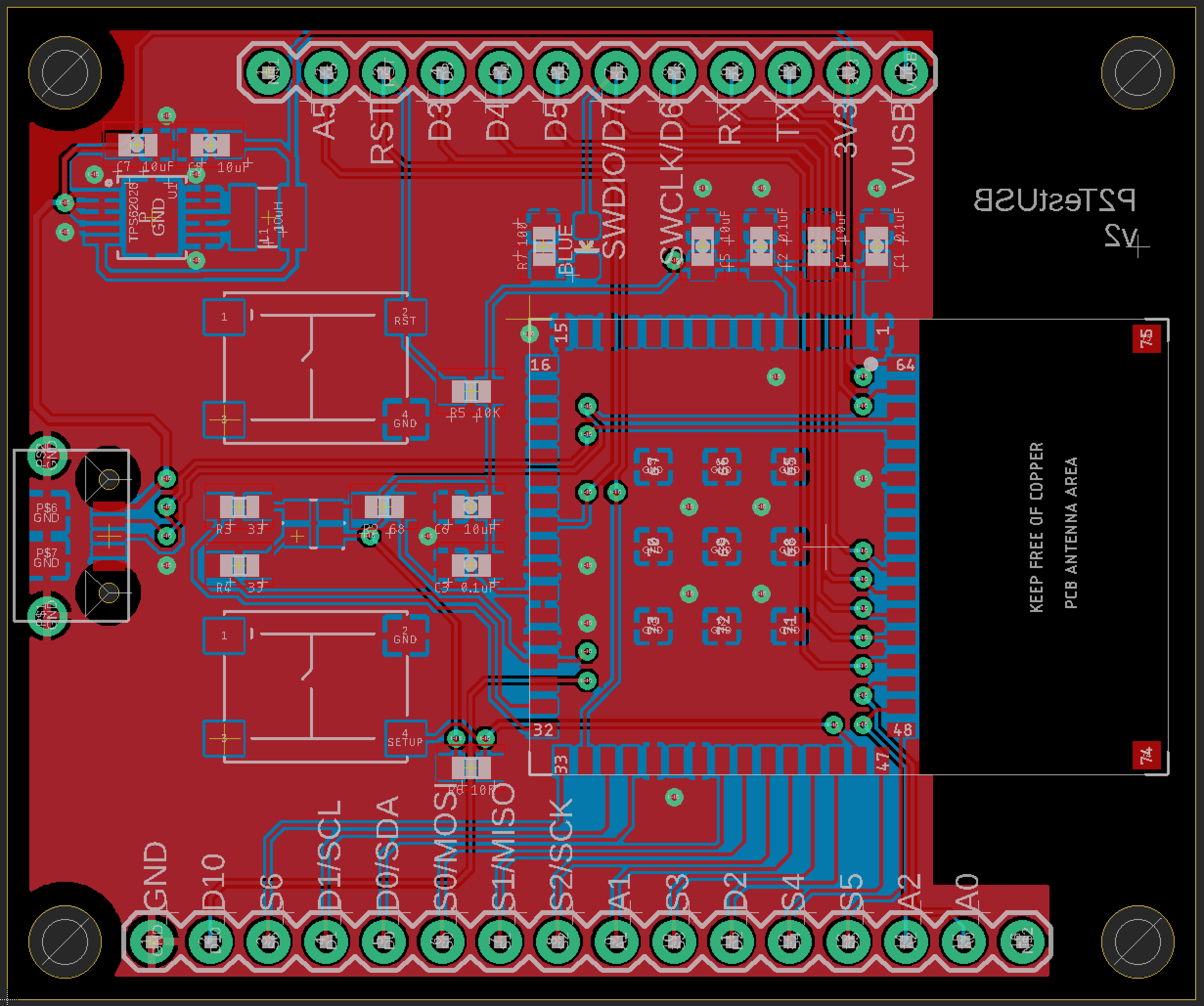
It's a two-layer board so it is easy and inexpensive to manufacture, and you can work with it on the free version of Eagle CAD.
The Eagle CAD design files can be downloaded as a zip file here. The files include:
- P2PlugTestUSB.sch EagleCAD schematic.
- P2PlugTestUSB.brd EagleCAD board layout file. This can also be submitted to OshPark.
- P2PlugTestUSBV1.zip Gerber files. This is what you submit to JLCPCB.
- P2PlugTestUSB.lbr Library file with all components in the schematic
- P2PlugTestUSB.cam Configuration file for generating the Gerber files.
RGB Status LED
We recommend including the RGB status LED as it is very difficult to see what the device is doing without it.
Device OS assumes a common anode RGB LED. This design uses a Cree CLMVC-FKA-CL1D1L71BB7C3C3 which is inexpensive and easily procured.
The design includes 1K current limiting resistors. These are much larger than necessary. They make the LED less blinding but still provide sufficient current to light the LEDs. If you want maximum brightness you should use the calculated values, 33 ohm on red, and 66 ohm on green and blue.
Buttons
The RESET and MODE buttons are highly recommended as well. Even if you don't include the buttons, having a way to trigger them, such as by test points, is beneficial.
The RESET and MODE lines have 10K pull-up resistors to 3V3.
This design uses a C&K PTS645SH50SMTR92 which is a 6.0mm SMD tactile button switch. It's much larger than the switch on the Boron but much easier to manipulate with your fingers.
You may want to use a smaller switch on your boards to save space.
USB Connector
A USB connector is highly recommended for software updates, serial debugging, and low-level operations like resetting keys.
This design uses an Amphenol FCI 10118194-0001LF SMD USB micro B receptacle. This is the same style of USB connector as on all Particle devices and evaluation boards.
Power supply
This design uses a Texas Instruments TPS62026DGQR 3.3V fixed voltage regulator. It supplies 600 mA at 3.3V from a 3.6V to 6V supply, which is perfect for USB power (5V).
It requires 10 uF input and output capacitors and a 10 uH inductor.
BoM (Bill of Materials)
| Quan | Part | Example | Price |
|---|---|---|---|
| 4 | 1K resistor 0603 | Panasonic ERJ-PB3D1001V | |
| 2 | 10K resistor 0603 | Panasonic ERJ-PA3J103V | |
| 3 | CAP CER 0.1UF 25V X7R 0603 | Samsung CL10B104KA8NNNC | |
| 5 | CAP CER 10UF 16V X5R 0805 | Murata GRM21BR61C106KE15L | |
| 1 | FIXED IND 10UH 1A 276 MOHM SMD | Bourns Inc. SRN3015-100M | $0.46 |
| 2 | 6.0mm tactile switch | C&K PTS645SH50SMTR92 | $0.21 |
| 1 | USB micro B connector | Amphenol FCI 10118194-0001LF | $0.42 |
| 1 | RGB LED 4PLCC | Cree CLMVC-FKA-CL1D1L71BB7C3C3 | $0.19 |
| 1 | LED Blue 0603 | Lite-On LTST-C193TBKT-5A | $0.47 |
| 1 | IC REG BUCK 3.3V 600MA 10MSOP | TI TPS62026DGQR | $2.36 |
| 1 | P2 Module | ||
| Male header pins 0.1" | Sullins PRPC040SAAN-RC |
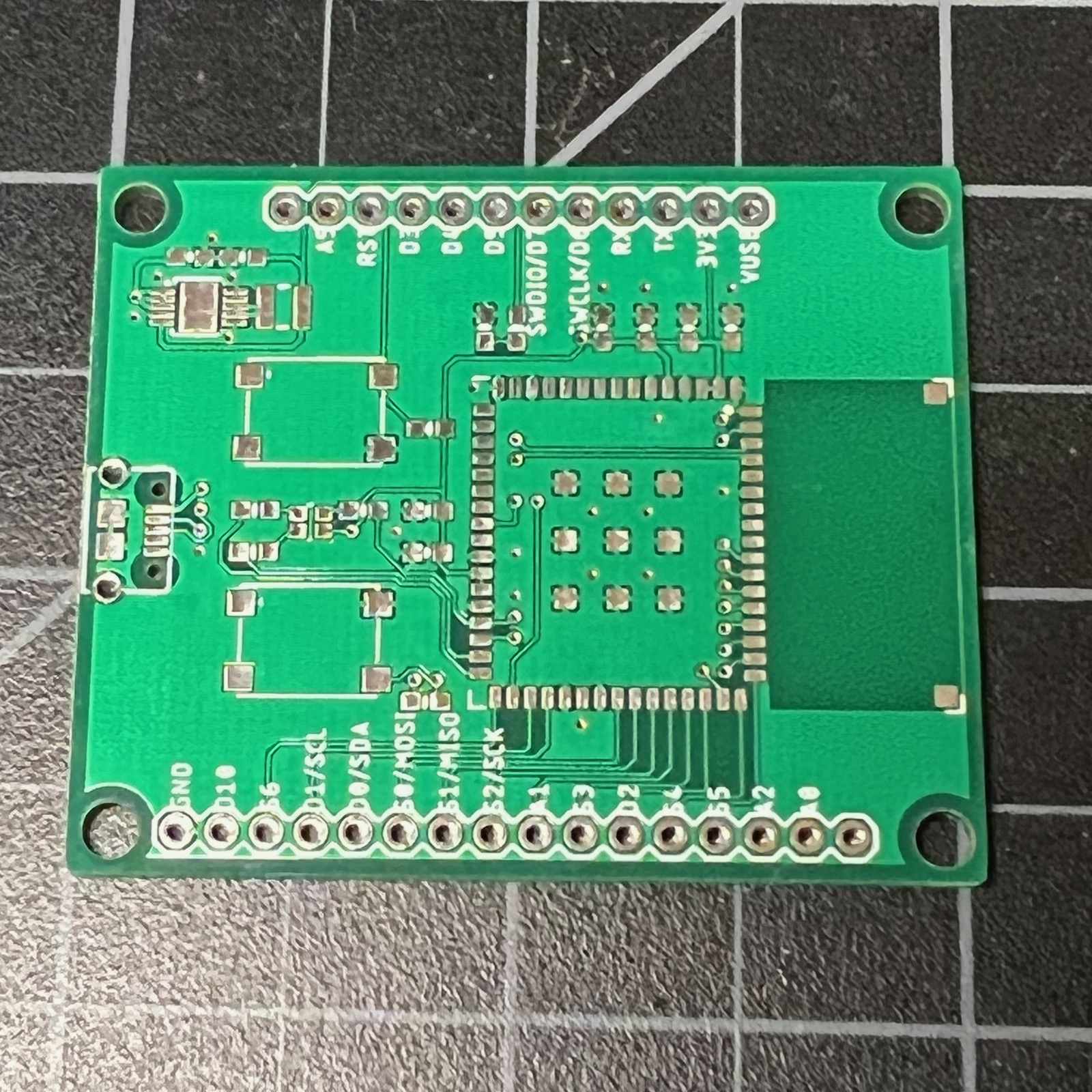
Assembly
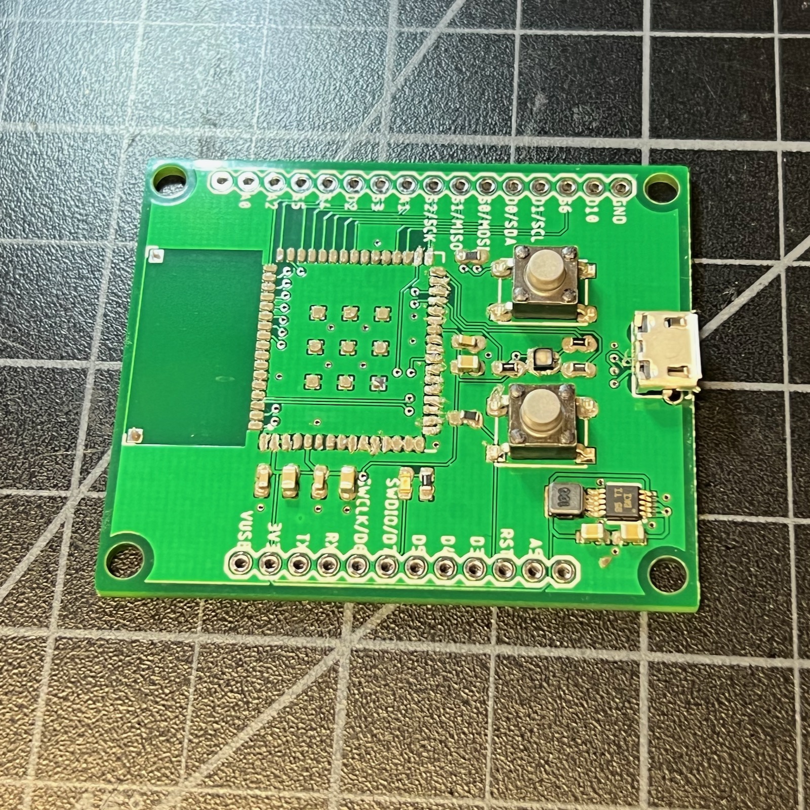
This is the board that I received from JLCPCB. I've also ordered many boards from OshPark.
The P2 has a lot of pins and it's a pain to apply solder paste by hand, though it can be done. Using a solder stencil will make your life much easier.
I ordered my stencil with my board from JLCPCB, but if you order a board from OshPark you can get the stencil separately from Osh Stencils.
I used a single stencil for the P2 first battery board and P2 first USB board, since the battery board only adds additional components; this is why you can see green (solder mask) through some of the stencil holes.
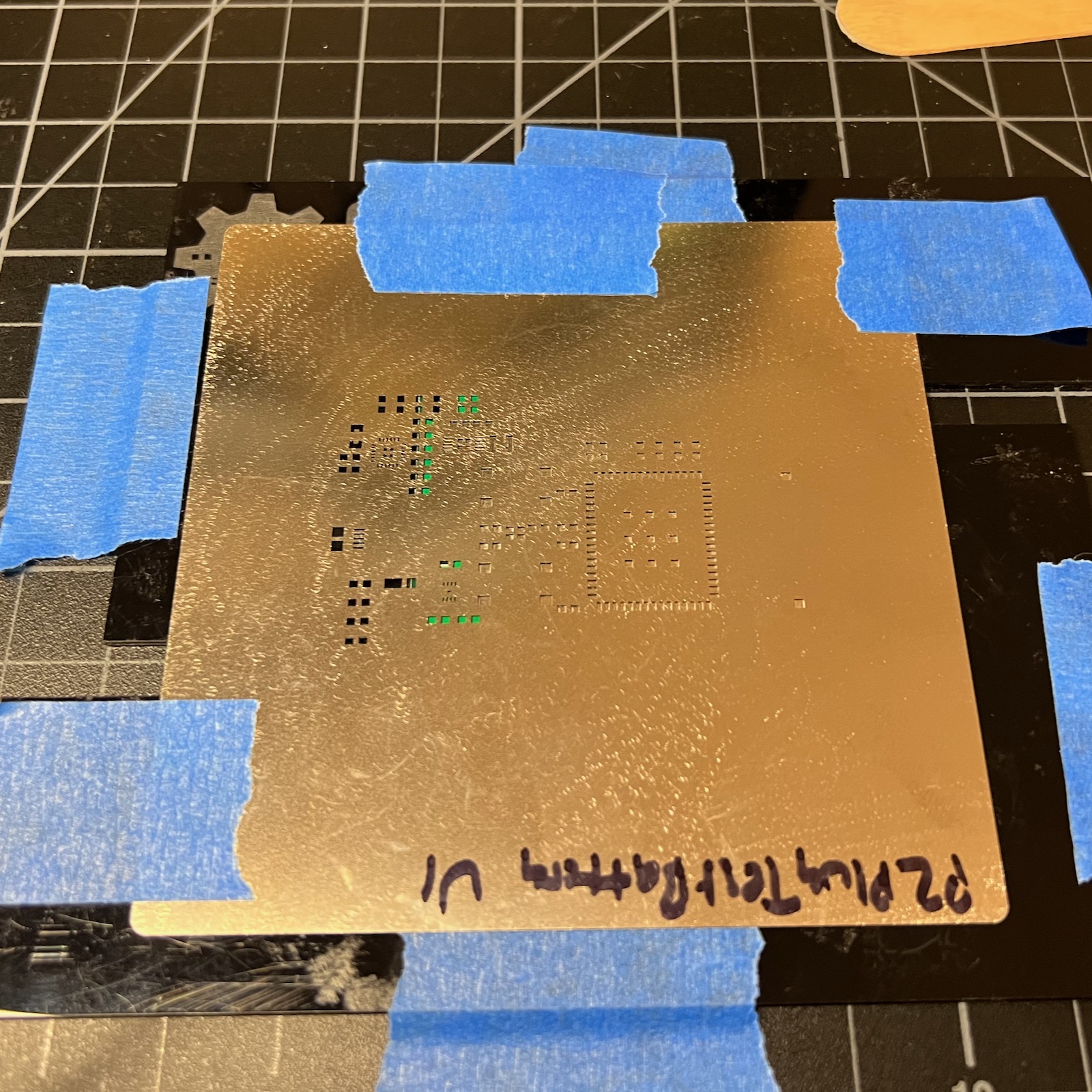
Since I used a 5 mil stainless steel stencil I frequently end up with too much solder paste on some of the tight pins. It's a good idea to clean this up; I use a small dental-style scraper tool for this.
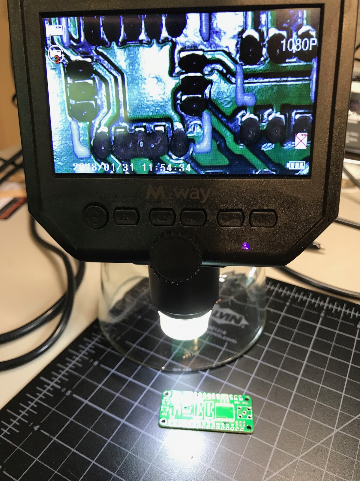
These inexpensive digital microscopes are ideal for assembling boards. I prefer this style with the integrated display vs. the ones that connect to a laptop. There's generally less lag with these, which makes it possible to do assembly and adjustment under the microscope while looking at the screen.
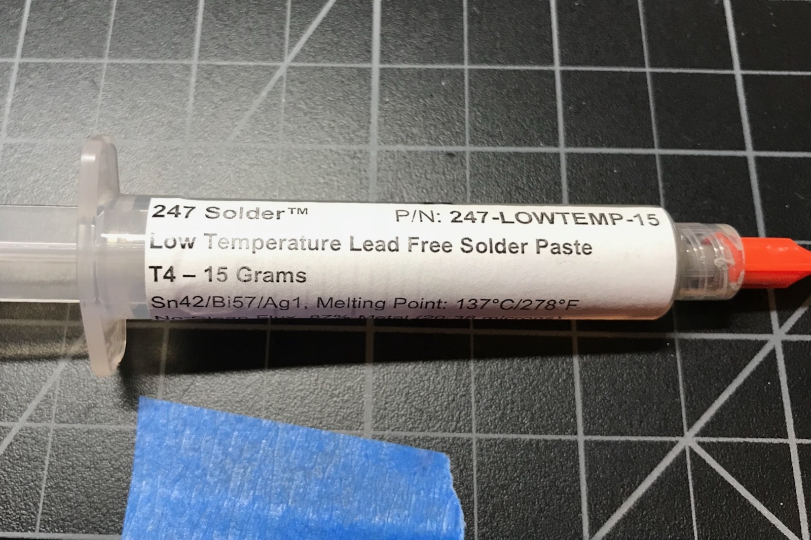
I prefer to use low-temperature lead-free solder paste, in this case Sn42/Bi57/Ag1 with a melting point 137°C (278°F).
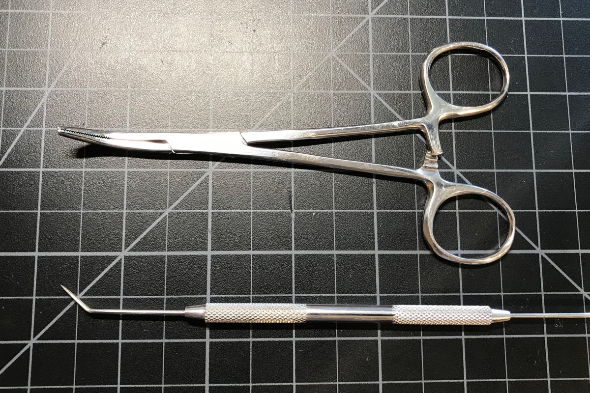
This board uses 0603-sized components that are easily placed by hand. I use these two tools, but some prefer tweezers over forceps.
This is my placement guide for the components:
And the board with most of the components (except the P2) roughly placed.
Reflow
I used an inexpensive T962 reflow oven to build this board. It's not the most accurate and there are some hot and cold zones, but works fine here.
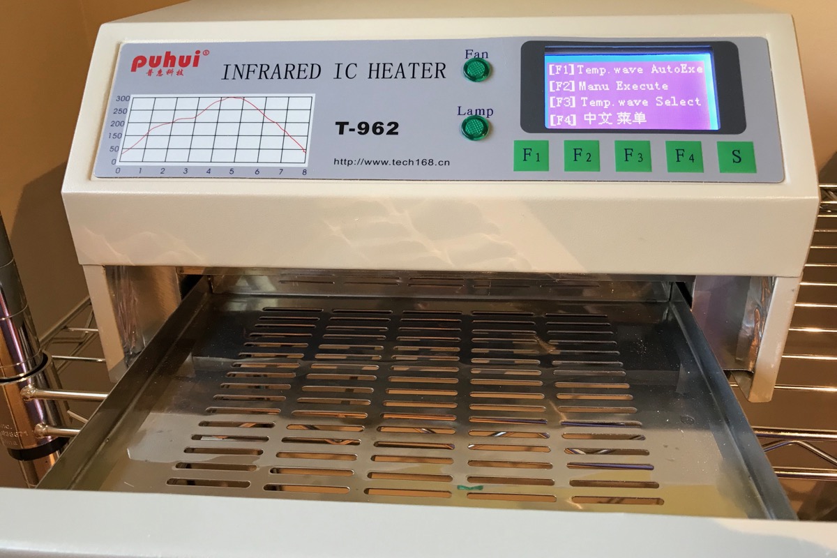
The Sn42/Bi57/Ag1 low-temperature solder paste can be reflowed using Wave 1.
Add the PTH components
There are three two-pin male headers on this board. These get soldered on by hand after the board is reflowed. They're cut from breakable male header pin strips.
Testing
You may want to first test the board by connecting a bench power supply to VUSB and GND at 5V. This is handy because you can set a reasonable current limit and see if the board is drawing current. This is optional, however, and you can always just throw caution to the wind and plug it into USB.
If all goes well, the status LED should light up white and then go to blinking dark blue (listening mode).
Try getting information about the board:
particle identify
And set Wi-Fi credentials so you can connect to the cloud:
particle serial wifi
Try entering other modes like DFU mode (blinking yellow). Try listing DFU devices and see if it shows up.
dfu-util -l
Celebrate making your first working P2 base board!
2022-05-02 (v2)
- Expanded the tRestrict and bRestrict around the antenna area. For best results remove as much copper GND plane from this area as well, and avoid GND loops around the antenna if at all possible.
2021-05-04
- Initial version