
Edge ML kit
The Edge ML kit provides a number of accessories that can be used with your Particle Photon 2 device. While the parts in the kit can be used with other Particle devices, the Edge ML features will only work on the P2 and Photon 2 at this time because of the limited amount of flash and RAM on older devices.
Your kit may be labeled Edge AI, and it has the same contents as described here.
Kit components
ADXL362 (GY362) accelerometer breakout
This breakout board allows you to detect motion and orientation. Using Edge ML you can filter for certain types of motion. It can also be used for wake-on-motion to wake from sleep.
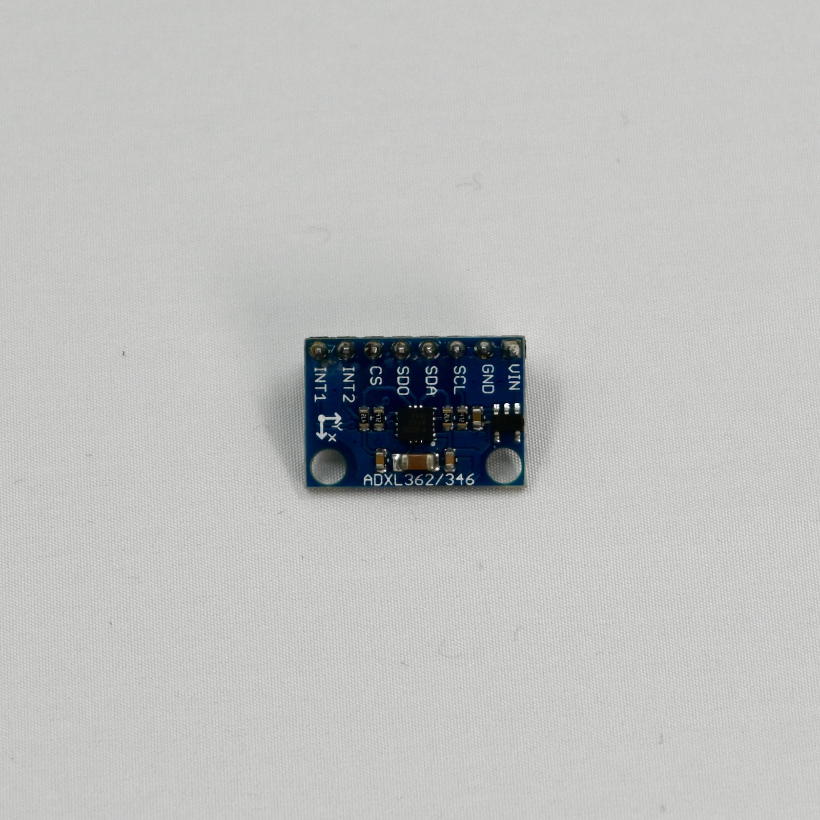
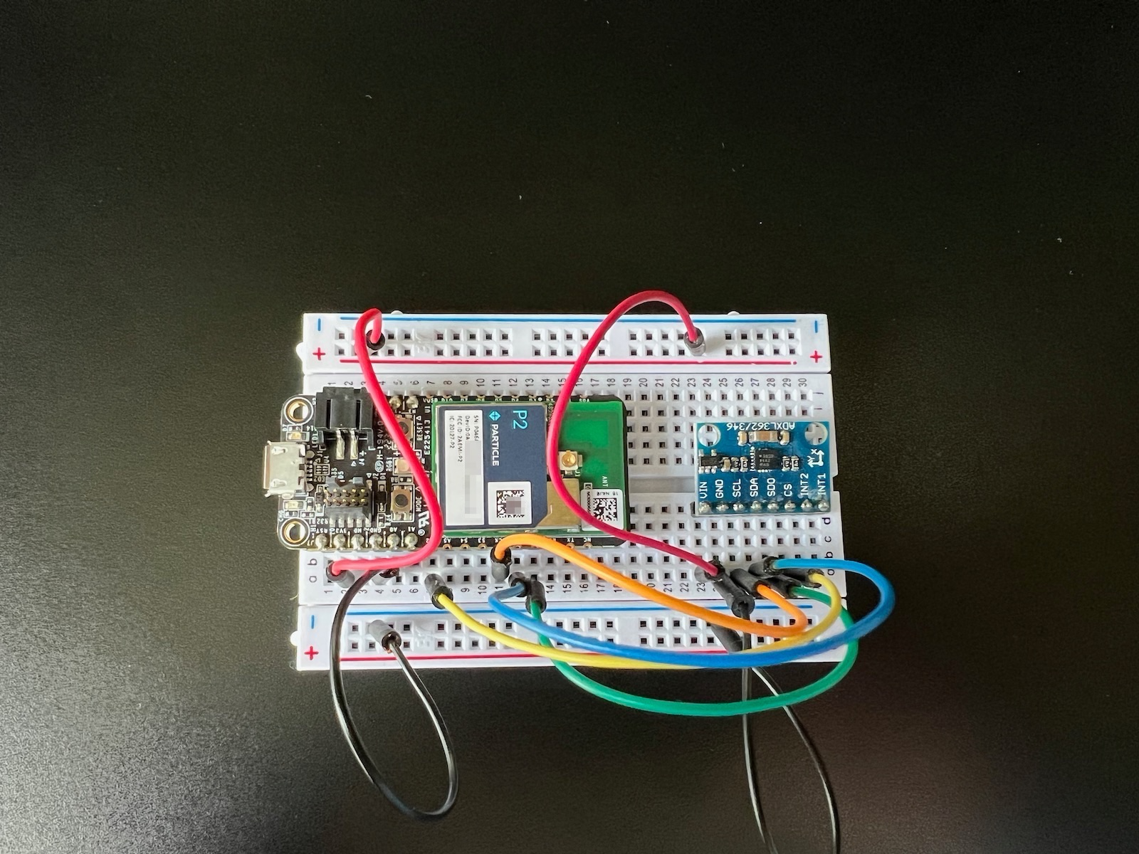
The connections on the breakout are:
| Breakout | Color | Connect To | Details |
|---|---|---|---|
| INT1 | Any | Any available GPIO if using interrupt 1 (optional) | |
| INT2 | Any | Any available GPIO if using interrupt 2 (optional) | |
| CS | Yellow | Any | SPI Chip Select. Use any available GPIO (required) |
| SDO | Green | MISO | SPI MISO (required) |
| SDI | Blue | MOSI | SPI MOSI (required) |
| SCL | Orange | SCK | SPI SDK (required). Not I2C SCL (D1)! |
| GND | Black | GND | Ground |
| VIN | Red | V3 | 3.3V power |
Use the ADXL362DMA library, or other compatible library. The library includes the full API definitions, as well as example code for getting raw accelerometer data and for doing simple orientation calculation.
PDM MEMS microphone
This breakout board is a digital microphone. It's intended for voice applications, not high-fidelity recording. Using Edge ML you cam implement similar voice commands using the microphone. It can also be used to detect specific sounds, such as an alarm siren.
There are machine learning tutorials using this microphone on the machine learning page.
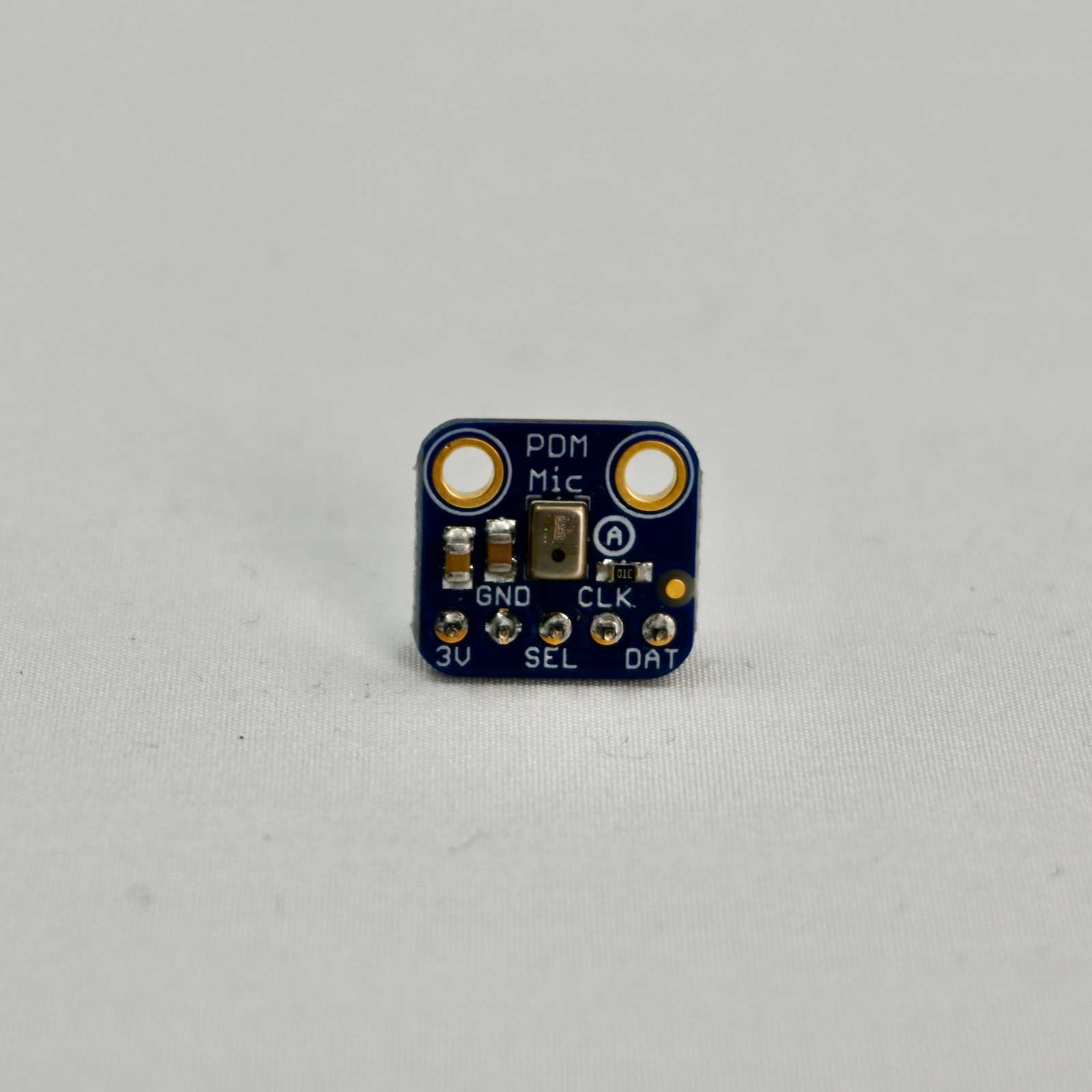
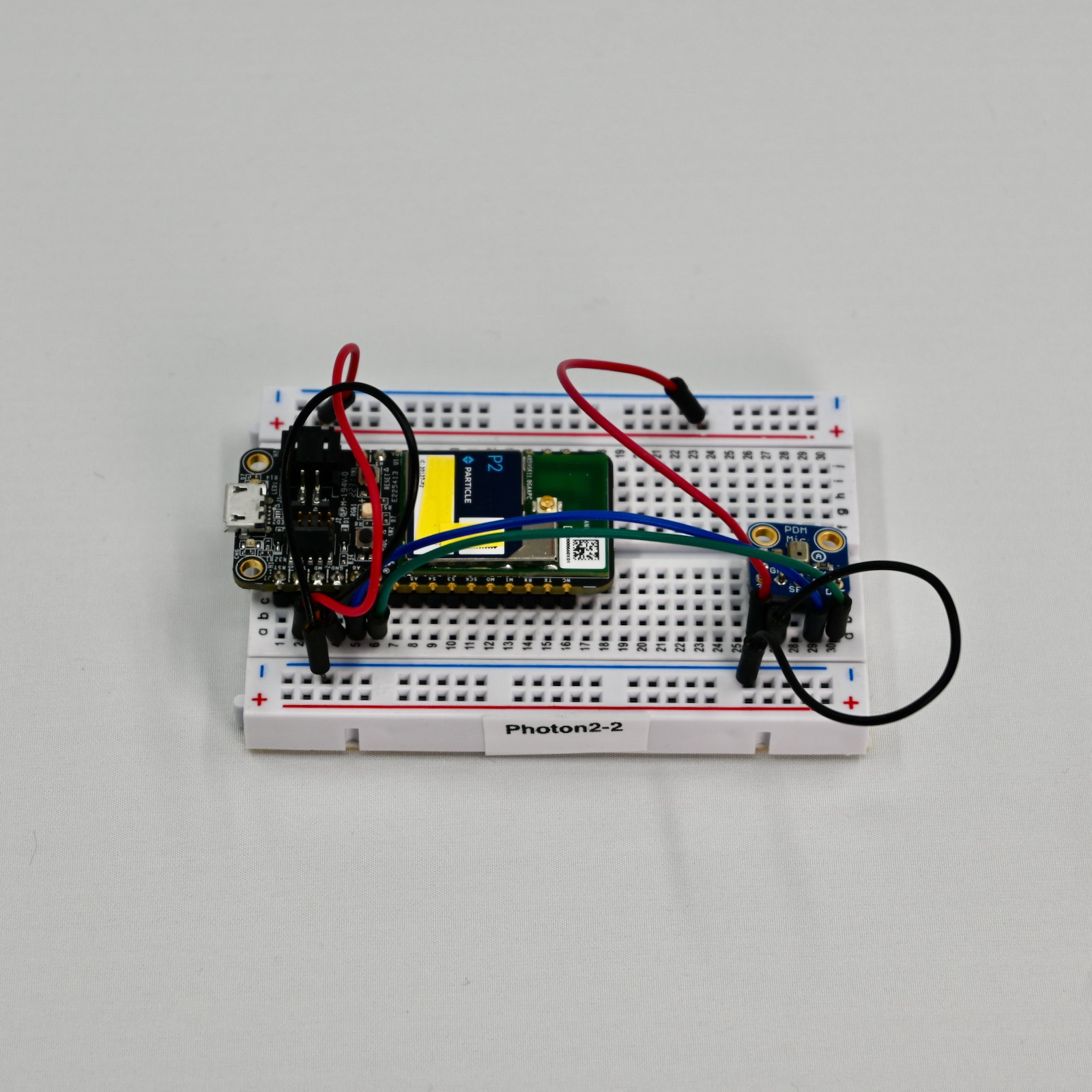
The connections on the breakout are:
| Breakout | Color | Connect To | Details |
|---|---|---|---|
| 3V | Red | 3V3 | 3.3V power |
| GND | Black | GND | Ground |
| SEL | NC | Typically leave unconnected, left/right select | |
| CLK | Blue | A0 | PDM Clock |
| DAT | Green | A1 | PDM Data |
Use the Microphone_PDM library. The library can be used for RTL872x (P2, Photon 2) and nRF52 (Boron, B-Series SoM, Tracker SoM, Argon). It does not support Gen 2 devices (Electron, E-Series, Photon, P1). The library includes sample code for capturing audio samples and additional information.
On the nRF52 you can use other GPIO for PDM clock and data, but using A0 and A1 will assure compatibility with the Photon 2.
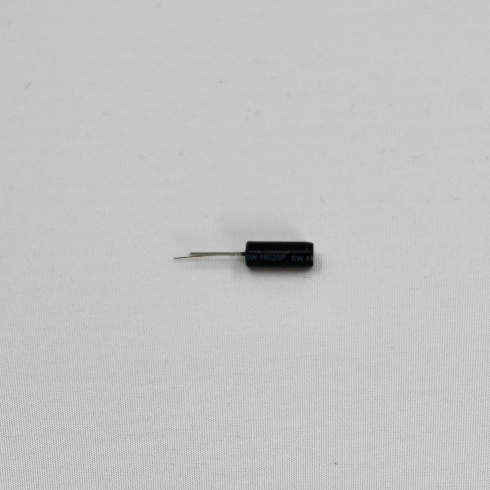
SW18020P vibration sensor
The vibration sensor a simple digital output that detects motion. This is simpler to use than the accelerometer, but less flexible. It is a two-terminal device that looks like an electrolytic capacitor.
We recommend that you connect one terminal to 3V3 and the other to an available GPIO, typically a D pin but an A pin can also be used.
Set the pin mode, for example if using D2:
pinMode(D2, INPUT_PULLDOWN);
To read the vibration status, use:
bool vibrating = (digitalRead(D2) == HIGH);
- Max voltage: 12V
- Max current: 50mA
- Conductive time: ~2ms
- Closed resistance <10 ohm
- Open resistance: >10M ohm
- Operating temperature range: -40 to 80 C
- Pull force of terminal: 500gf for 1 min
- Operating lifespan: up to 200,000 cycles
- Dimensions (excluding pin): 4.77mm (0.19in) diameter x 11.18mm (0.44in) length
- Dimensions (including pin): 21.5mm (0.85") length
- Weight: 0.22g (.008oz)
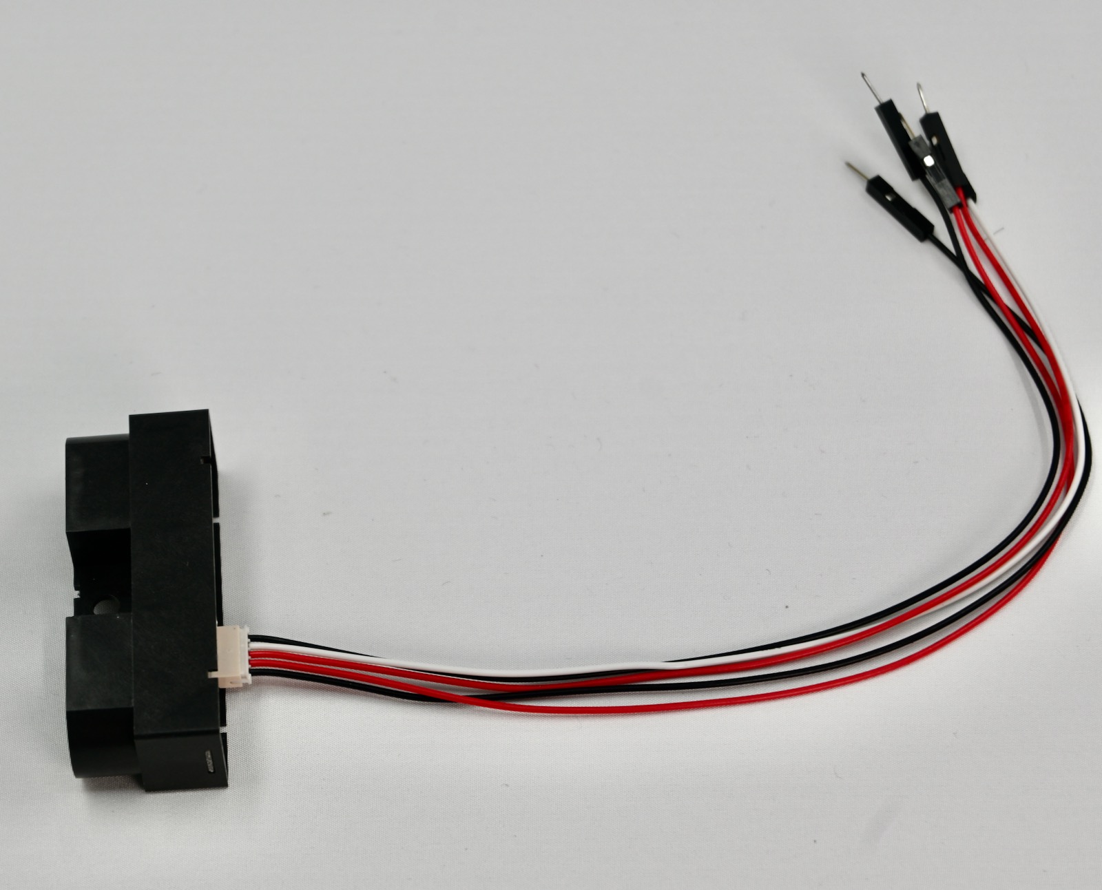
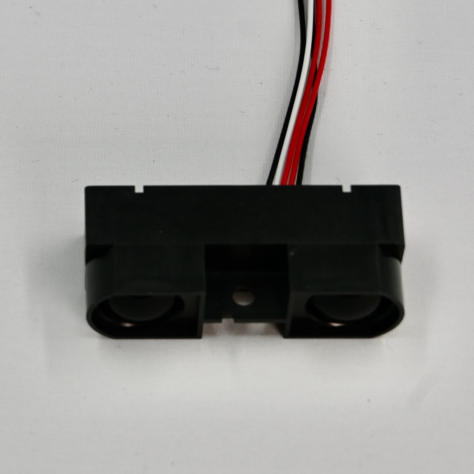
GP2Y0A710K0F 100-550cm IR Distance sensor
This sensor measures distance, and provides an analog output that is proportional to distance that you can connect to an A pin and use analogRead() to read. Note that this sensor requires 5V so you cannot use it when powered by a LiPo battery but it will work when connected to USB. The analog output is a maximum of 3V so it's safe to connect to an analog input, which supports a maximum of 3.3V.
| Pin | Color | Connect To | Description |
|---|---|---|---|
| 1 | Black | GND | Ground |
| 2 | Red | VUSB | 5V Supply |
| 3 | Red | VUSB | 5V Supply |
| 4 | White | A pin |
Output voltage |
| 5 | Black | GND | Ground |
The sensor has 5 output pins, but the red and black (power) lines are duplicated.
The white wire should be connected to an available analog input (A) pin.
Note that the analog value is inverse from the voltage, and not linear. See the datasheet for more information.
| Distance | Voltage | Value |
|---|---|---|
| 100cm | 2.5V | 3102 |
| 200cm | 1.8V | 2233 |
| 550cm | 0.25V | 310 |
- Distance measuring range: 100cm to 550cm
- Supply voltage: 4.5V to 5.5V
- Operating current: 30 mA
- Sensor datasheet
Loudness sensor with LM2904 opamp
The loudness sensor provides an analog output that is proportional to the loudness. This is easier to use than the microphone, but of course only detects that there is sound, not its specific characteristics. This sensor requires 3.6V minimum, so it's best to use it powered by VUSB, but this means that you will not be able to use it when powered by a LiPo battery.
Care should be used when setting the adjustable gain - if you set it to maximum gain and it is very loud, the output could exceed the recommended maximum of 3.3V on analog inputs.
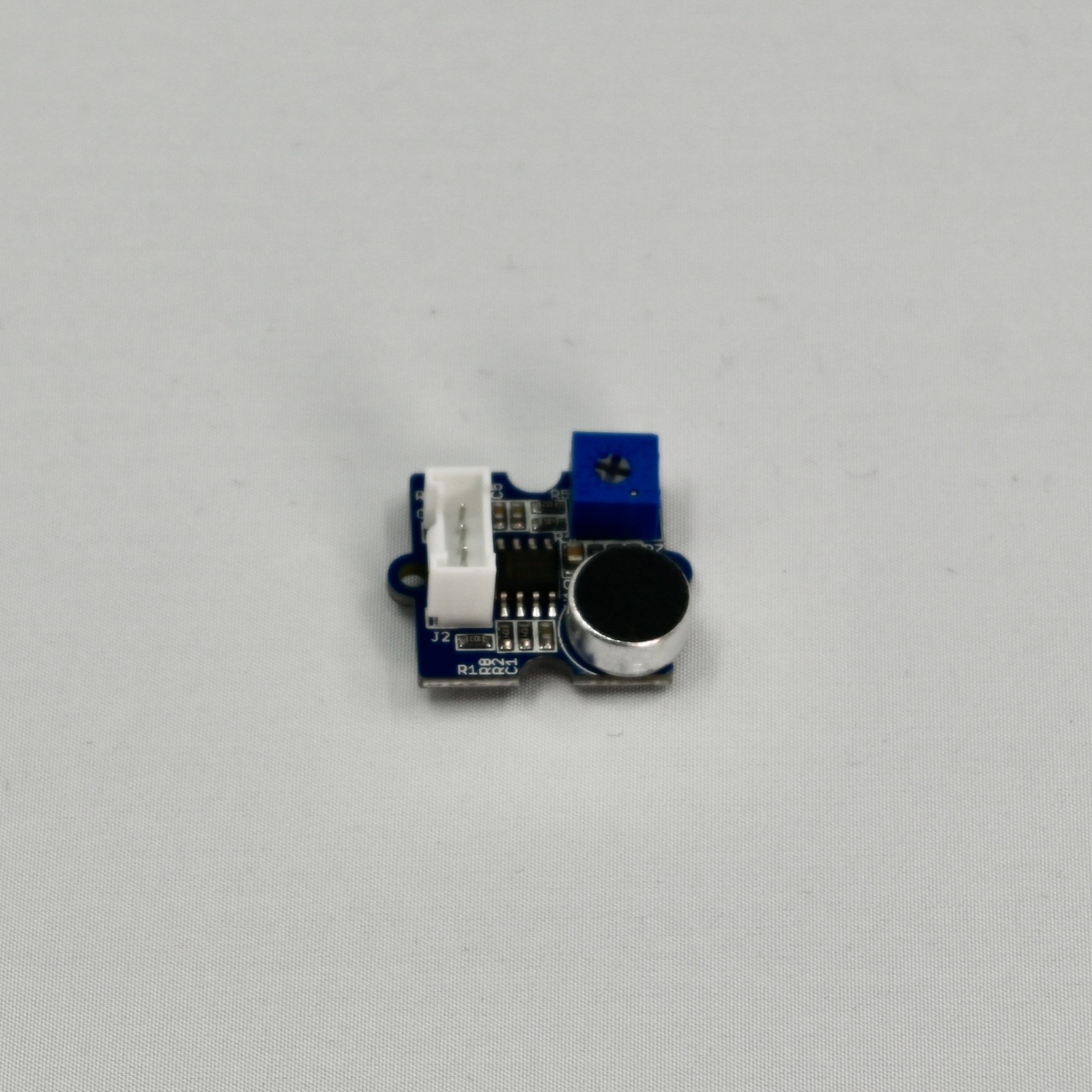
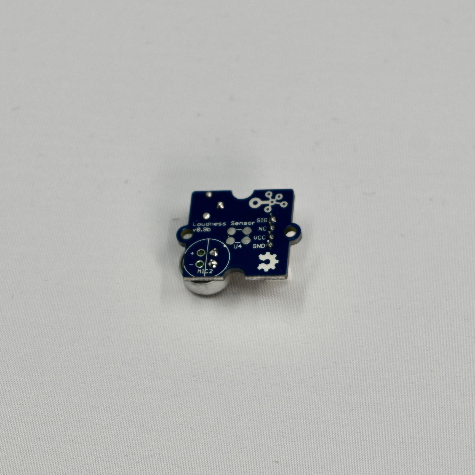
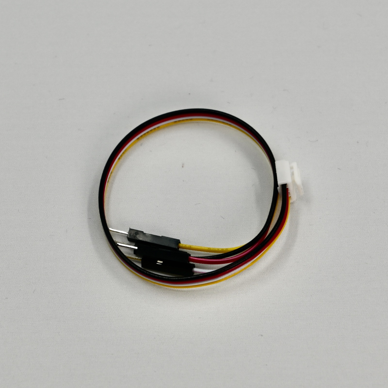
The breakout includes a Grove connector to flying leads cable. It's also possible to use a 4-pin Grove-to-Grove cable if you have a board with a Grove connector and a Grove Feather Adapter.
| Breakout | Color | Connect To | Details |
|---|---|---|---|
| GND | Black | GND | Ground |
| 3V | Red | 3V3 | 3.3V power |
| NC | White | Not used | |
| SIG | Yellow | Any A |
Connect to an analog input pin |
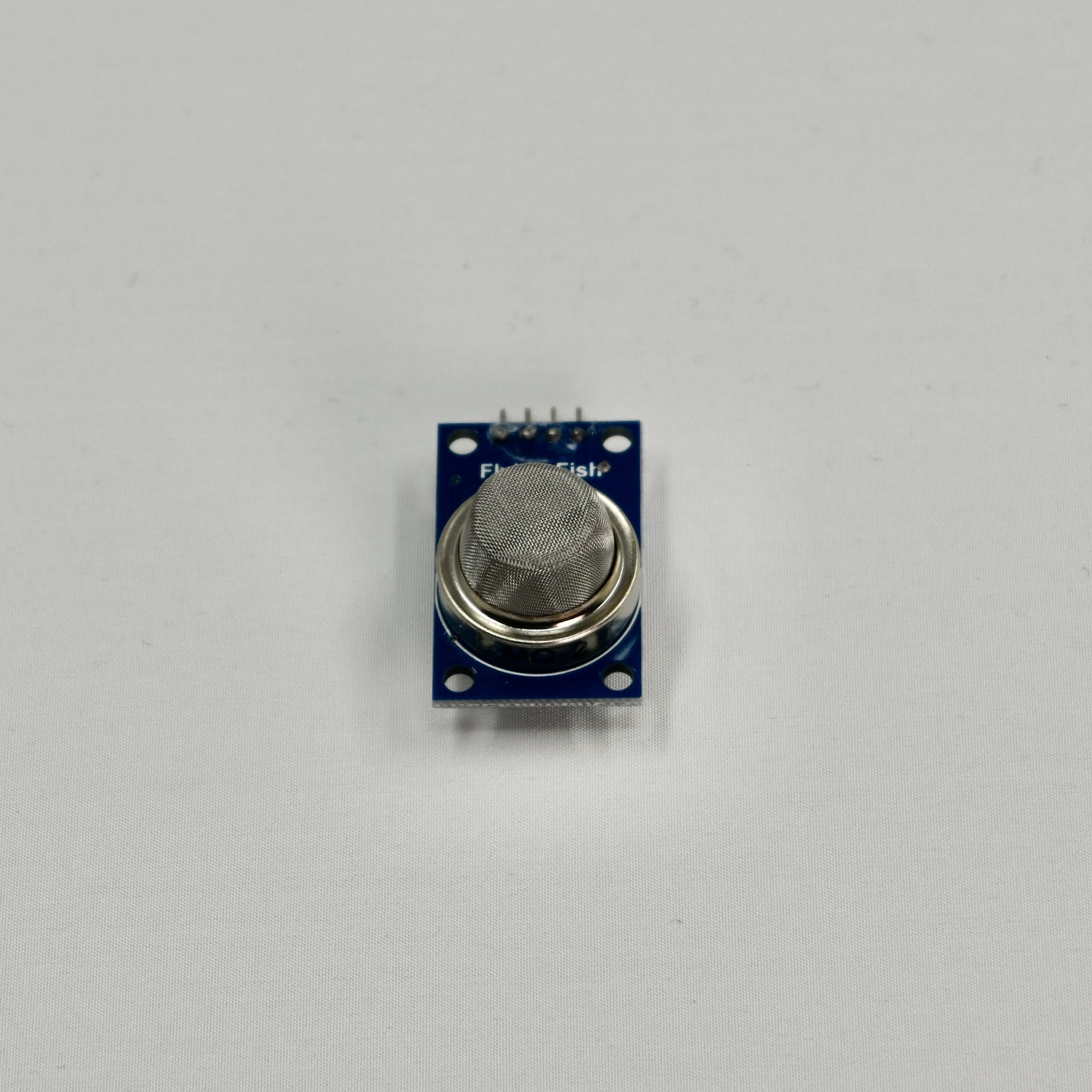
MQ2 gas sensor for LPG, i-butane, propane, methane, alcohol
This is a sensor for detecting the presence of various combustible gasses. It requires 5V so you cannot use it when powered by a LiPo battery but it will work when connected to USB. Also, this type of sensor has a small heater inside, which is not well suited for being battery powered.
The potentiometer determines the threshold for the digital output.
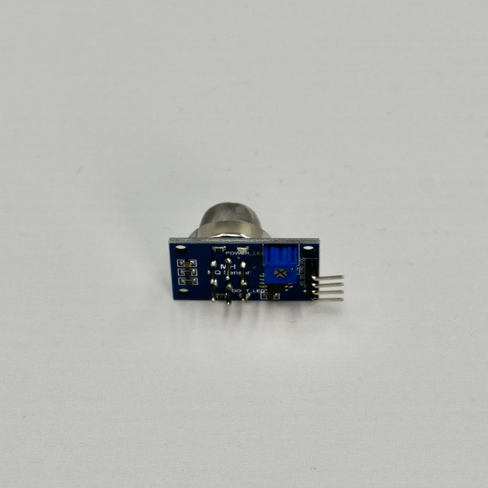
You don't need to connect both D0 and A0, you can use just one of them.
- D0 can be connected to any digital (
D) or analog (A) input on your Particle device. - A0 can be connected to any analog (
A) input on your Particle device.
When reading the analog input, low concentration of gas will result in values closer to 0. Values closer to 4095 (the maximum) indicate high levels of detectable gasses. By using the analog output, you can adjust the sensitivity in software.
The potentiometer controls the gas level level that switches D0 on and off.
There are also other members of the MQ sensor family (not included in this kit):
- MQ3 alcohol vapor
- MQ5 LP gas and natural gas
- MQ9 Carbon monoxide
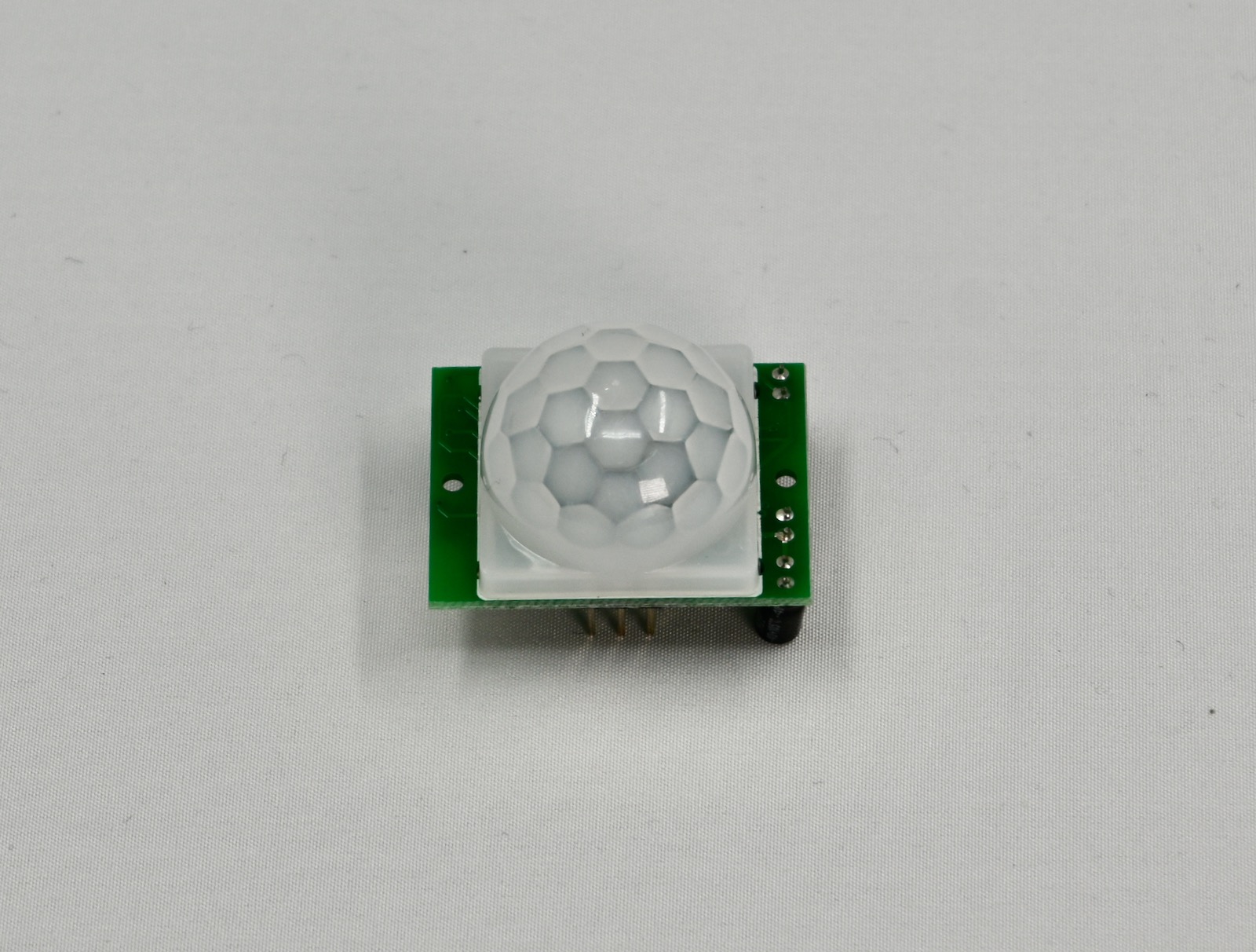
HC-SR501 PIR motion sensor
This sensor detects heat using a passive infrared (PIR) sensor. It's typically used to sense humans (and other warm-blooded animals). It requires 5V so you cannot use it when powered by a LiPo battery but it will work when connected to USB. The output is only 3.3V so it's safe to connect to any available GPIO.
| Breakout | Connect To | Details |
|---|---|---|
| +5V | VUSB | 5V power (when powered by USB) |
| OUT | Any | Connect to any available GPIO |
| GND | GND | Ground |
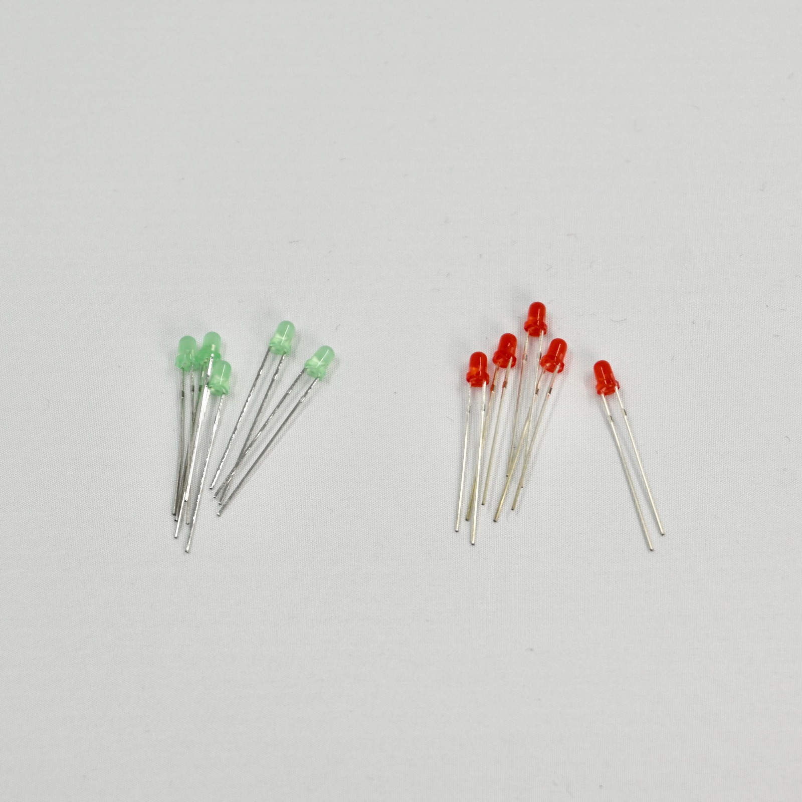
LEDs
Several light-emitting diodes (LEDs) are included in the kit, and can be used as indicator lights. The LEDs in your kit may vary slightly from the items pictured here.
LEDs require a current limiting resistor. Typically you will use 1KΩ (Brown - Black - Red - Gold) so the LED will not be overly bright.
You can use 330 Ω (Orange - Orange - Brown - Gold) if you need maximum brightness. This will require changing the pin drive strength on nRF52840 devices (Boron, B-Series SoM, Tracker, E404X, Argon) in software.
- The longer lead is the positive connection or anode
- The shorter lead in the negative connection or cathode. The case may also have a flattened spot on the cathode side.
- The current limiting resistor can be on either the positive or negative side, but there must be a separate current limiting resistor for each LED if you have more than one.
Instead of the LEDs above, your kit may include different LEDs:

- IR LED (blue-ish)
- White LED (clear with rounded top)
- Red LED (included with most kits that contain a photo transistor instead of the white LED to reduce confusion)
- Photo transistor (clear and flat on top)
Resistors
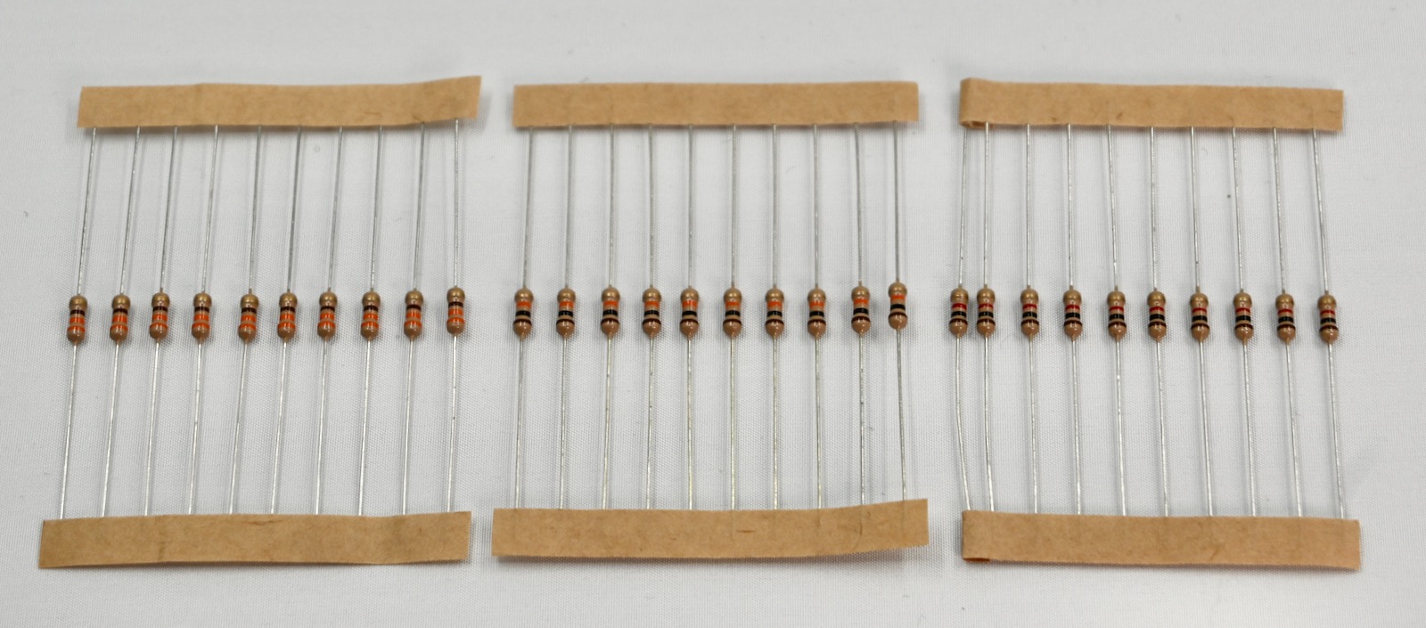
Resistors have a standardized color code.
| Color | Value | Value | Multiplier | Tolerance |
| Black | 0 | 0 | × 1 | |
| Brown | 1 | 1 | × 10 | 1 % |
| Red | 2 | 2 | × 100 | 2 % |
| Orange | 3 | 3 | × 1K | |
| Yellow | 4 | 4 | × 10K | |
| Green | 5 | 5 | × 100K | 0.5 % |
| Blue | 6 | 6 | × 1M | 0.25 % |
| Violet | 7 | 7 | × 10M | 0.1 % |
| Gray | 8 | 8 | × 100M | 0.05 % |
| White | 9 | 9 | × 1G | |
| Gold | × 0.1 | 5 % | ||
| Silver | × 0.01 | 10 % |
The resistors in the kit include:
| Color | Resistance | Usage |
|---|---|---|
| Orange - Orange - Brown - Gold | 330 Ω | LED current limiting |
| Brown - Black - Red - Gold | 1KΩ | Transistor gate or current limiting |
| Brown - Black - Orange - Gold | 10KΩ | Pull-up or pull-down |
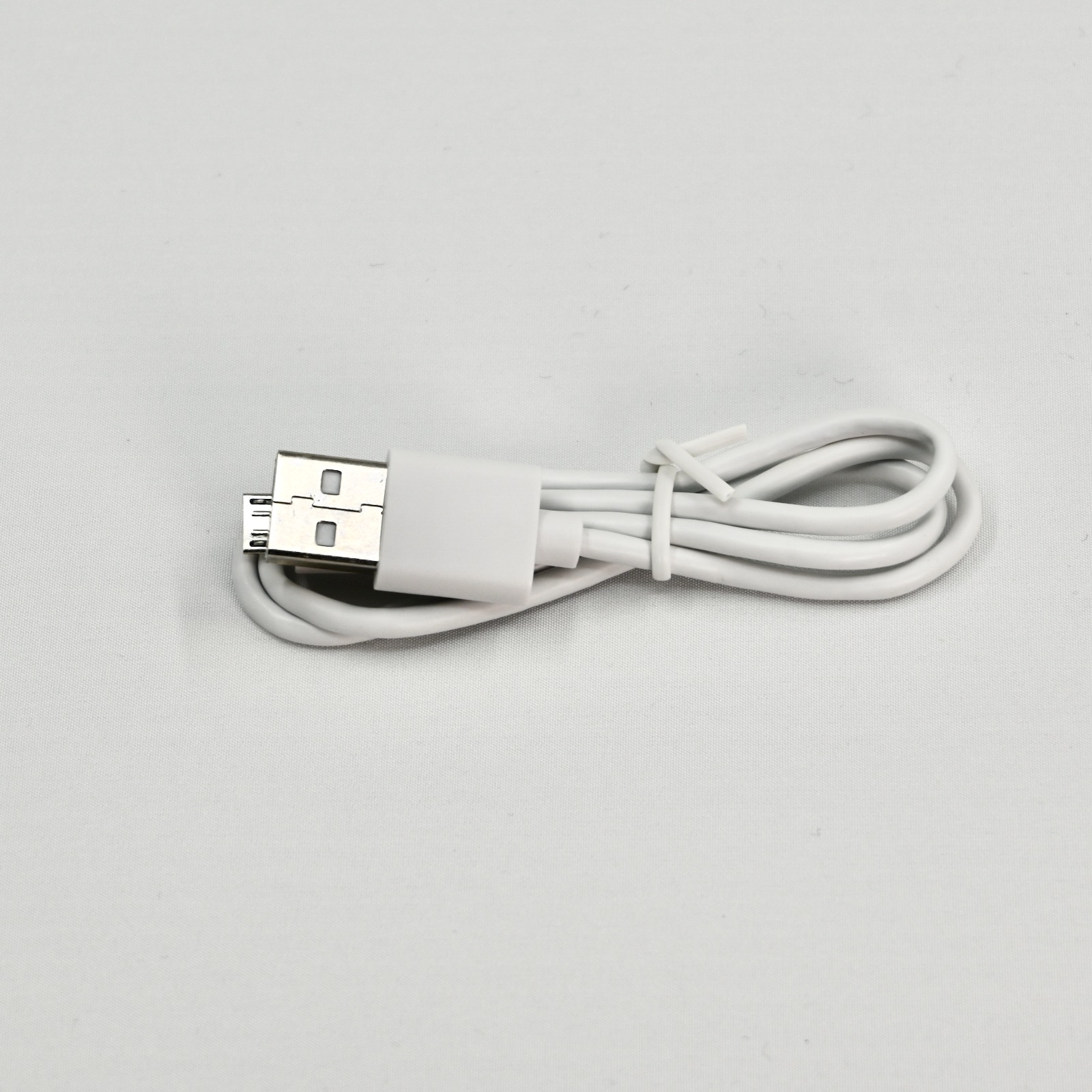
USB
The kit contains a standard USB-A to Micro-B cable. You can use any USB cable, but for programming over USB make sure you are using a full USB data cable and not a "charging only" cable.
Breadboard
The kit contains a solderless breadboard.
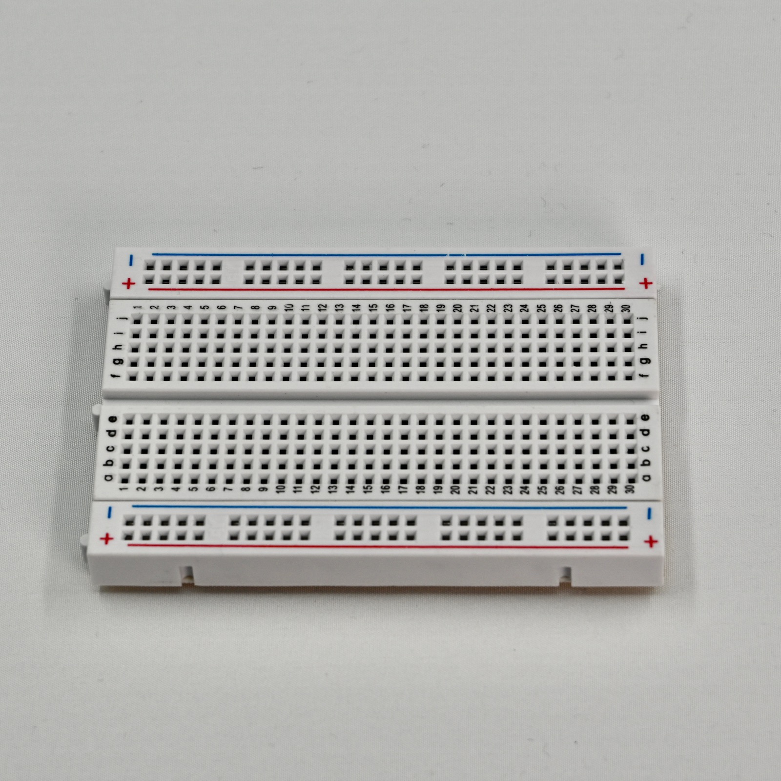
Electrically, the holes in a solderless breadboard are connected like this:
Source: Wikipedia, Florian Schäffer, License: CC BY-SA 4.0
Jumper wires
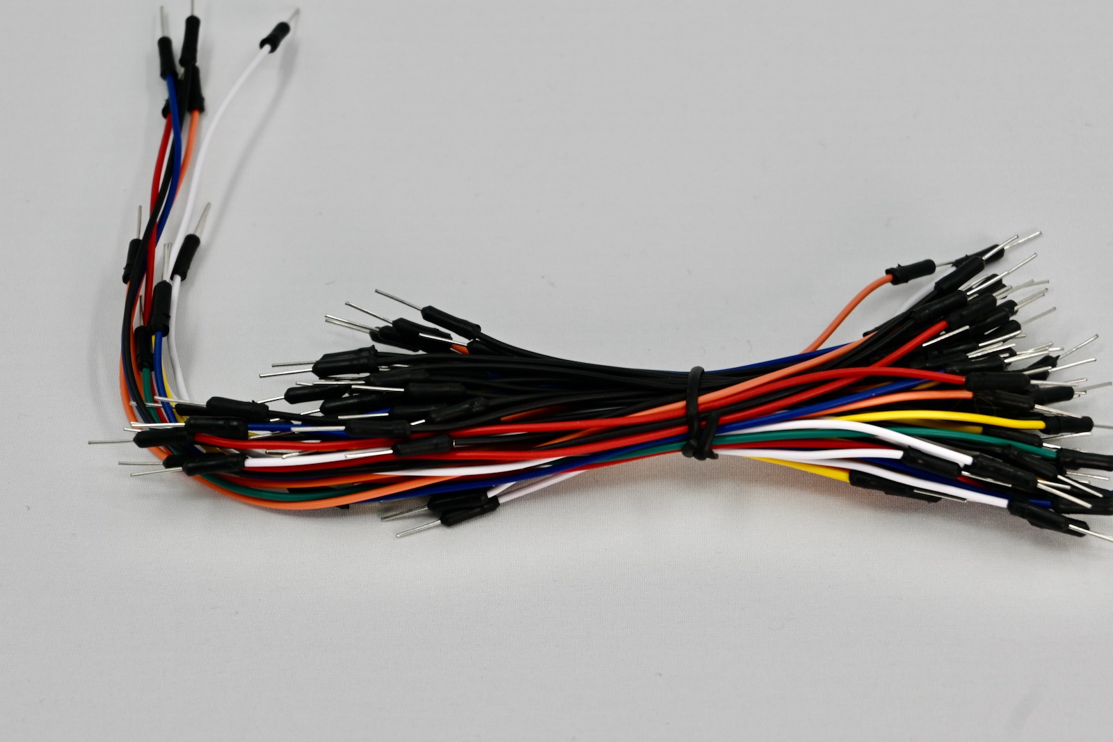
We recommend that you use:
- Red for 3V3 (3.3V power)
- Black for GND (ground)