
Legacy accessories
Shield shield
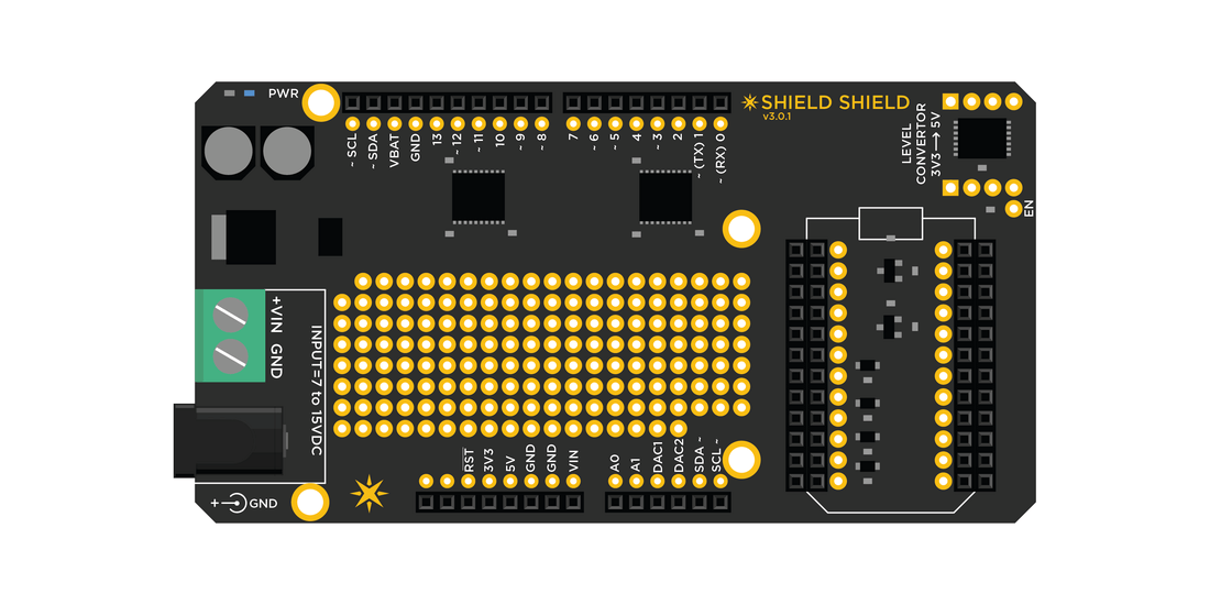
Sometimes life can be a little difficult in the land of electronics when two systems talk a different voltage language. How do you make them talk to each other without making one of them burn out? The Shield Shield is the answer. This shield performs all the necessary voltage translation and provides an Arduino-compatible footprint to make it easier for you to plug in your existing Arduino shields or talk to other 5V hardware.
Shield shield - operation
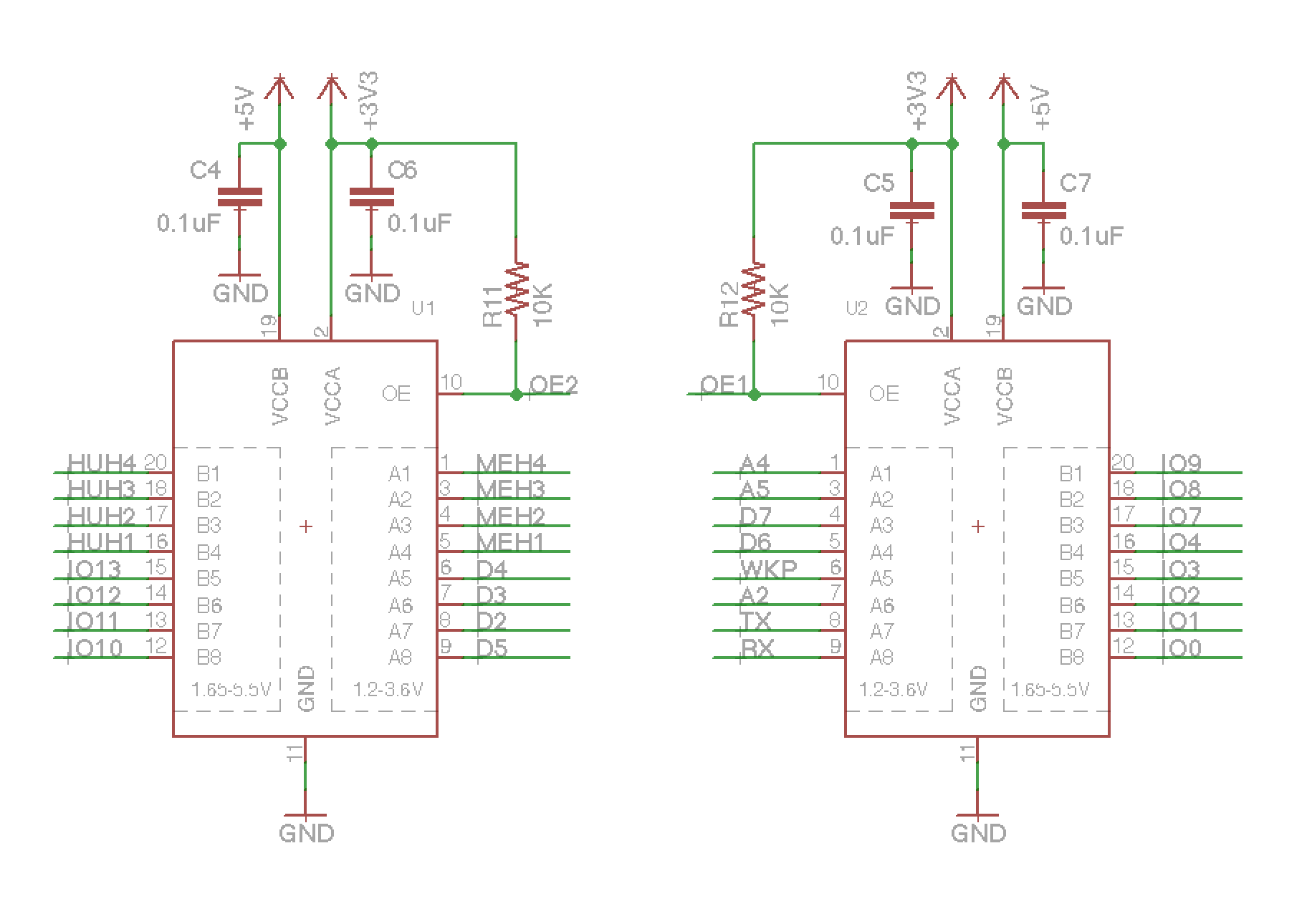
We use Texas Instruments TXB0108PWR to do the voltage translation in between the Particle's device's 3.3V to a 5V logic. Unlike other IO pins, the analog pins are rated at only a max of 3.3V and NOT 5.0V. Please remember NOT to exceed this voltage at anytime. The shield has an on-board voltage regulator and can be powered from 7V to 15V DC source. You could also power it via the USB plug on the Particle device alone but the current would be limited to 500mA.
Shield shield schematic - TXB0108PWR
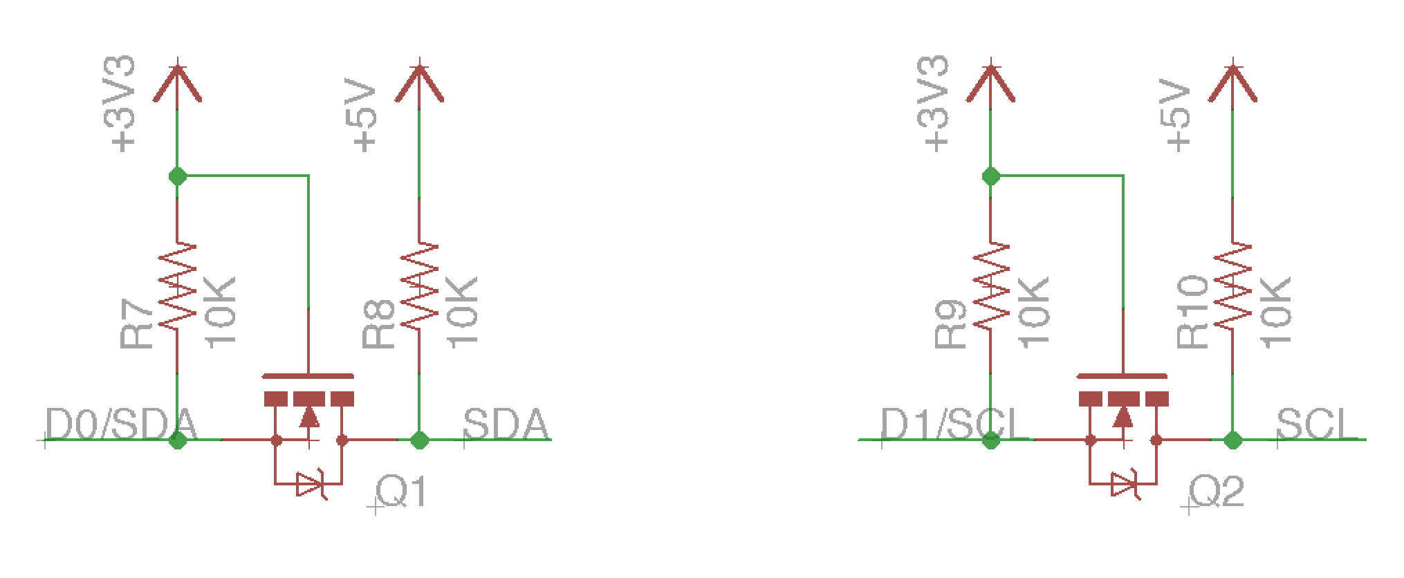
The new version of the Shield Shield (v3.x.x) uses dedicated MOSFET based voltage translation on the I2C lines. We also decided to add a prototyping area in empty space in the middle of the shield.
Shield shield schematic - MOSFET I2C
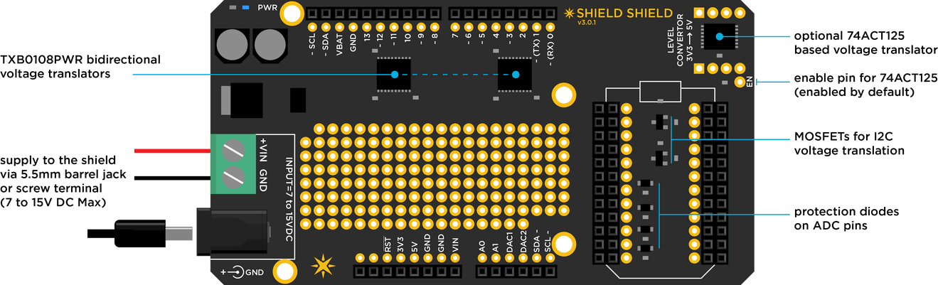
Note: One drawback of using the TXB0108PWR as a voltage translator is that it is only capable of driving loads at short distances. Long length wires will introduce excessive capacitive loading and cause the auto direction detection to fail. To overcome this drawback, the shield shield also has an optional on-board 74ABT125 buffer that is capable of driving heavier loads in one direction. A user can jumper wire to whichever IO pin they would like to be translated to 5V.
Shield shield - pin mapping
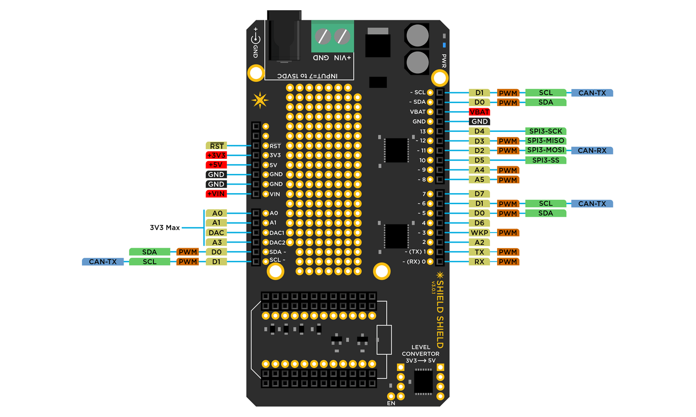
| Shield | Photon | Peripherals |
|---|---|---|
| 0 | RX | Serial1 RX,PWM |
| 1 | TX | Serial1 TX,PWM |
| 2 | A2 | SPI1_SS |
| 3 | WKP | PWM,ADC |
| 4 | D6 | |
| 5 | D0 | SDA,PWM |
| 6 | D1 | SCL,PWM,CAN_TX |
| 7 | D7 | |
| 8 | A5 | SPI1_MOSI,PWM |
| 9 | A4 | SPI1_MISO,PWM |
| 10 | D5 | SPI3_SS |
| 11 | D2 | SPI3_MOSI,PWM,CAN_RX |
| 12 | D3 | SPI3_MISO,PWM |
| 13 | D4 | SPI3_SCK |
| A0 | A0 | ADC** |
| A1 | A1 | ADC** |
| A2 | DAC1 | DAC,ADC** |
| A3 | DAC2 | SPI1_SCL,DAC,ADC** |
| A4 | D0 | SDA,PWM* |
| A5 | D1 | SCL,PWM*,CAN_TX |
* Note: These pins can also function as 3.3V PWM outputs or 3.3V Servo outputs.
** Note: ADC inputs are 3.3V max.
IMPORTANT: The Shield Shield does not map the Particle device's pins to like-numbered pins on the Arduino. In other words, D0 on the Particle device is not the same as D0 on the Arduino. Please review the pin mapping table to the right and plan accordingly.
Shield shield - specifications (v3.x.x)
- Operating voltage: 7 to 15V DC
- Current consumption: standalone 7mA at 9V DC
- Voltage translator with auto direction detect: TXB0108PWR
- Dedicated MOSFET based voltage translator on I2C lines
- Separate unidirectional quad buffer for driving heavy loads: 74ACT125
- Diode protection on ADC pins
- Dimensions: 3.4" x 2.1"
- Weight: 28 gms

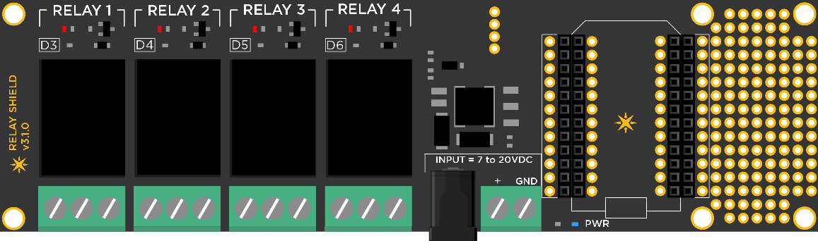
Relay shield
The Relay Shield allows you to take over the world, one electric appliance at a time. Want to control a lamp, fan, coffee machine, aquarium pumps or garden sprinklers? Then this is a solution for you!
The shield comes with four relays that are rated at a max of 220V @10Amp allowing you to control any electric appliance rated at under 2000 Watts. You are not just limited to an appliance though; any gadget that requires high voltage and/or a lot of current can be controlled with this shield.
We have even provided a small prototyping area around the shield for you to add more components or connectors. A temperature sensor to go along with your brewer, maybe?
IMPORTANT: This shield provides regulated power (5V) to the seated Particle device and relays. However, it does not support power to the devices controlled by the relays.
Relay shield - library
If you're already logged into Build.particle.io then you can jump directly to the library to get going quickly and easily with the RelayShield library, which wraps all the features in easy-to-use functions.
Examples include:
- Blink a Relay - How to turn a relay on and off
- Blink all the Relays - An extension on the simplest case
- Internet Relays - Creating Particle.function()s so that you can turn relays on and off over the Internet
Relay shield - operation
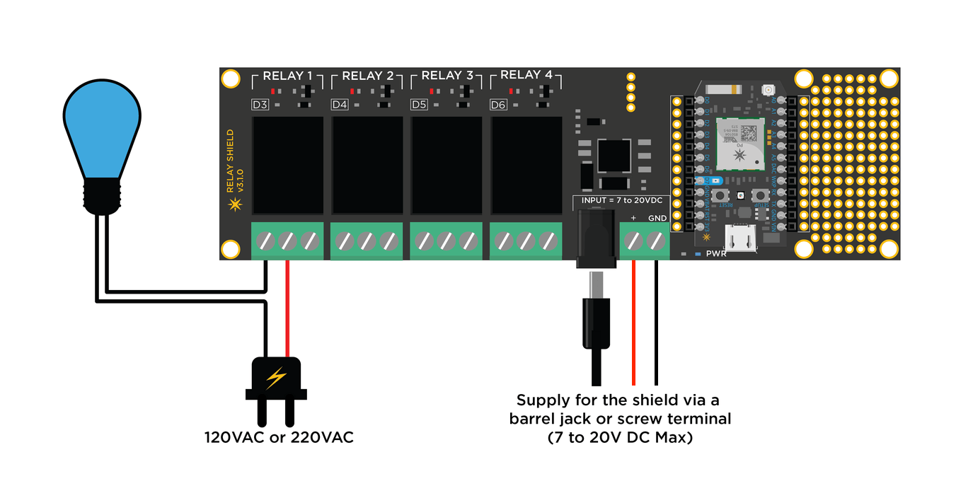
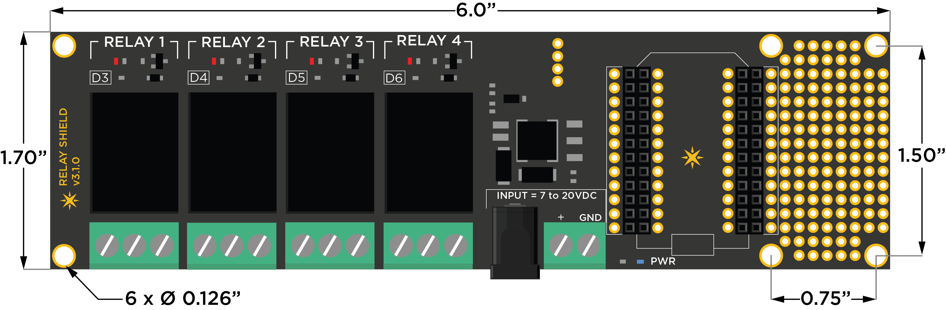
The schematic for the relay shield is simple and self explanatory. The shield has four relays that are controlled by pins D3, D4, D5 and D6 on the Particle device. Each relay is triggered via a NPN transistor that takes a control signal from the Particle device and switches the relay coil ON and OFF, which in turn makes or breaks the electrical contact on the output. There is also a fly-back diode connected across the coil to help protect the transistor from high voltage transients caused during switching.
NOTE: On the under side of the relay shield (top center), you will see 4 solder pads that are by default bridged via traces. You can scratch off the trace to disconnect the control pin from the preassigned ones (D3 to D6) and wire up based on your project requirement.
Relay shield schematic - control
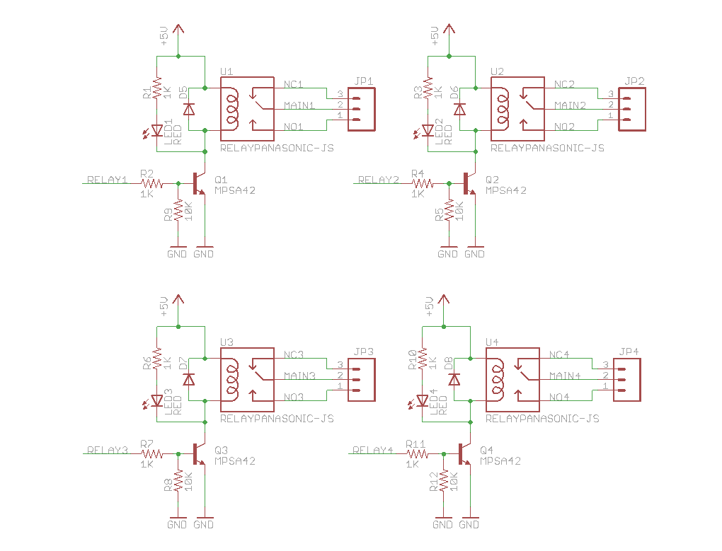
The relays are SPDT (Single Pole Double Throw) type, which means they have three terminals at the output: COMMON (COMM), Normally Open (NO) and Normally Closed (NC). We can either connect the load in between the COMM and NO or COMM and NC terminals. When connected in between COMM and NO, the output remains open/disconnected when the relay is turned OFF and closes/connects when the relay is turned ON. In the later case, the output remains closed/connected when the relay is OFF and opens/disconnects when the relay is ON.
Relay shield schematic - power supply
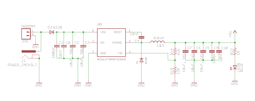
The Relay Shield uses a high efficiency Richtek RT8259 switch mode voltage regulator that provides a constant 5V to the Particle device and the relays. The regulator is rated at 1.2A max output current which is ample enough to power the Particle device, the four relays and still have left over for other things you may decided to connect later. You can power the shield via the 5.5mm barrel jack or through the screw terminal. There is a reverse polarity protection diode in place so that you don't fry the electronics by plugging in the wires in reverse!
Here is an example setup to control a light bulb. The relay acts like a switch which is normally open and when pin D3 on the Particle device is turned HIGH, it activates Relay 1 thereby closing the circuit on the light bulb and turning it ON. Ta dah!
Relay shield - sample setup
Relay shield - sample code
int RELAY1 = D3;
int RELAY2 = D4;
int RELAY3 = D5;
int RELAY4 = D6;

void setup()
{
   //Initilize the relay control pins as output
   pinMode(RELAY1, OUTPUT);
   pinMode(RELAY2, OUTPUT);
   pinMode(RELAY3, OUTPUT);
   pinMode(RELAY4, OUTPUT);
   // Initialize all relays to an OFF state
   digitalWrite(RELAY1, LOW);
   digitalWrite(RELAY2, LOW);
   digitalWrite(RELAY3, LOW);
   digitalWrite(RELAY4, LOW);

   //register the Particle function
   Particle.function("relay", relayControl);
}

void loop()
{
   // This loops for ever
}

// command format r1,HIGH
int relayControl(String command)
{
  int relayState = 0;
  // parse the relay number
  int relayNumber = command.charAt(1) - '0';
  // do a sanity check
  if (relayNumber < 1 || relayNumber > 4) return -1;

  // find out the state of the relay
  if (command.substring(3,7) == "HIGH") relayState = 1;
  else if (command.substring(3,6) == "LOW") relayState = 0;
  else return -1;

  // write to the appropriate relay
  digitalWrite(relayNumber+2, relayState);
  return 1;
}
An example API request to this function would look something like this:
POST /v1/devices/{DEVICE_ID}/relay

# EXAMPLE REQUEST
curl https://api.particle.io/v1/devices/0123456789abcdef/relay \
  -H "Authorization: Bearer f8a4d380cb6ffffffffffffffffffaf5e496ddf0c0"  -d params=r1,HIGH
Replace the access token with a valid access token, such as from particle token create.
Relay shield - specifications (v3.x.x)
- Operating voltage: 7 to 20V DC
- Current consumption: 150mA min to 290mA max (at 9V DC)
- Relay Max Voltage: 220V AC
- Relay Max Current: 10Amp at 125V AC
- Relay Part Number: JS1-5V-F Data Sheet
- Dimensions: 6.0" x 1.7"
- Weight: 80 gms
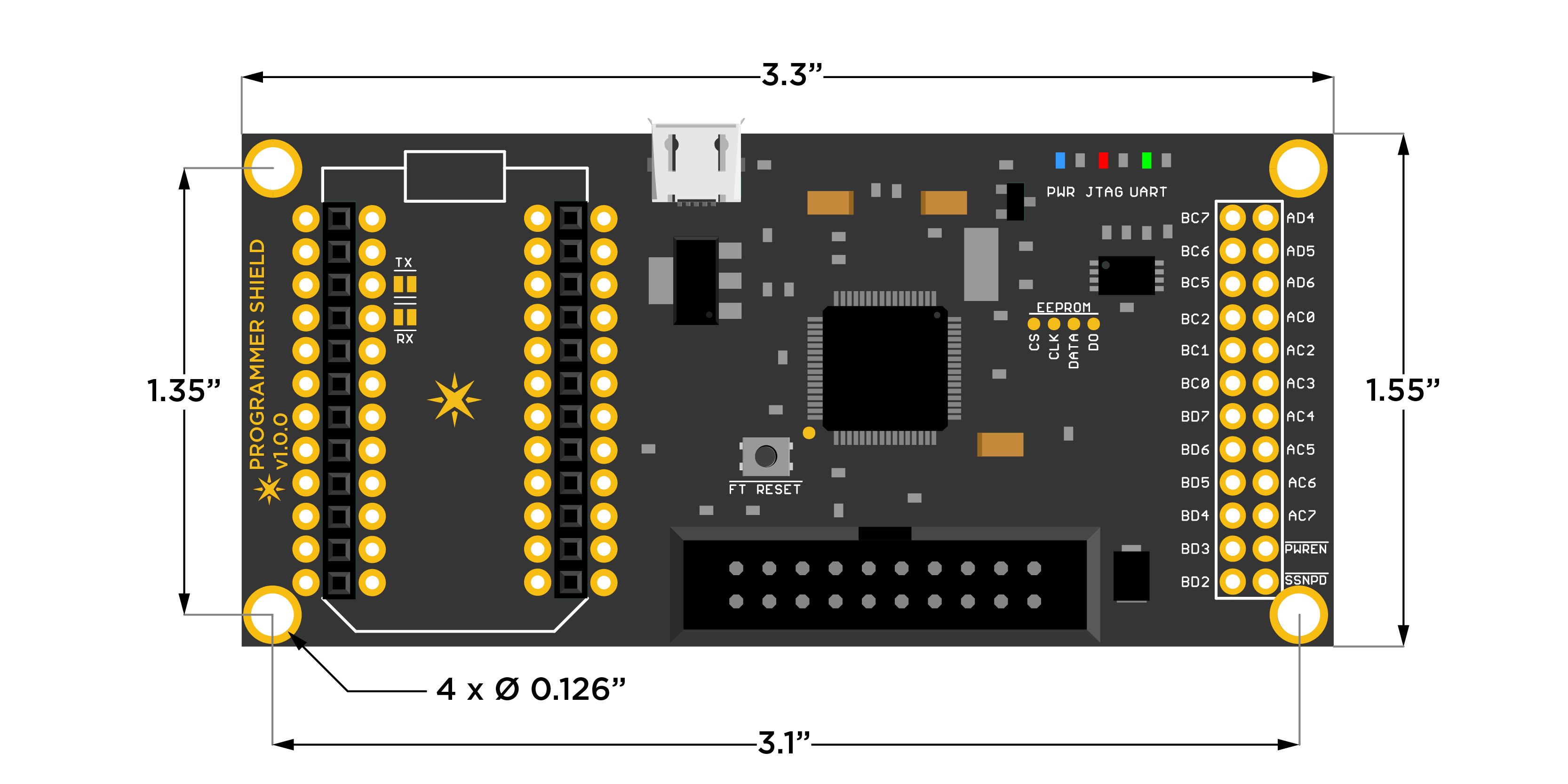
Programmer shield
Do you want to gain complete control over your Particle device right down to its every bit of memory space? or watch as your code gets executed and debug it? Then this shield should be able to pacify that control freak inside of you.
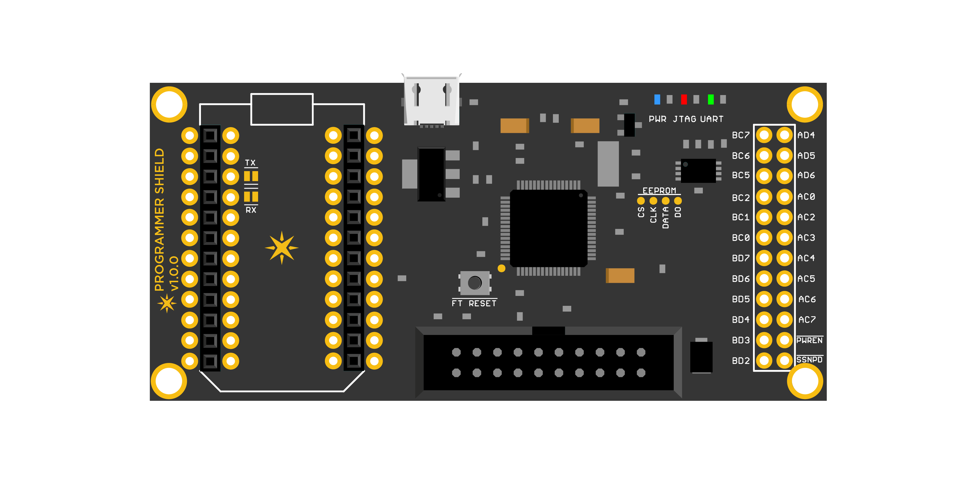
This is a FT2232H based JTAG programmer shield that is compatible with OpenOCD and Broadcom's WICED IDE. The FT2232 chip is setup to provide an USB-JTAG and USB-UART interface simultaneously. The FT2232 can be also reconfigured by the user by reprogramming the on-board config EEPROM. The unused pins are clearly marked and broken out into easy to access header holes.
The USB-UART interface is connected to the TX and RX of a Particle device and communicates via Serial1
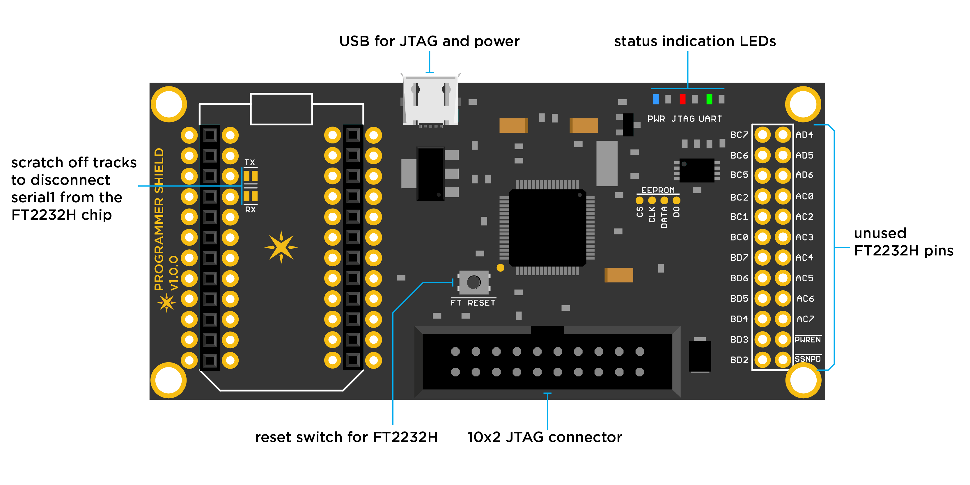
For more instructions on setting up OpenOCD and using the Programmer Shield, please read through the README at the landing page of the Programmer Shield repository on GitHub, linked below:
https://github.com/particle-iot/shields/tree/master/photon-shields/programmer-shield
Programmer shield - specifications
- Operating supply: USB
- Current consumption:
- Dimensions: 1.55" x 3.3"
- Weight: 18 gms
- Compatibility: OpenOCD and WICED IDE
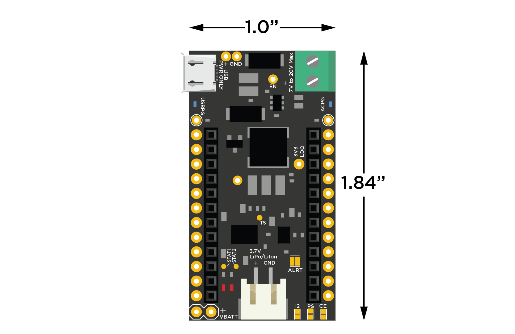
Power shield
The Power Shield, as the name implies, allows the Particle device to be powered from different types of power sources. The shield has an intelligent battery charger and power management unit along with a wide input voltage regulator and an I2C based fuel-gauge. You can power a Particle device with either a USB plug or a DC supply of anywhere from 7 to 20VDC and charge a 3.7V LiPo battery all at the same time.
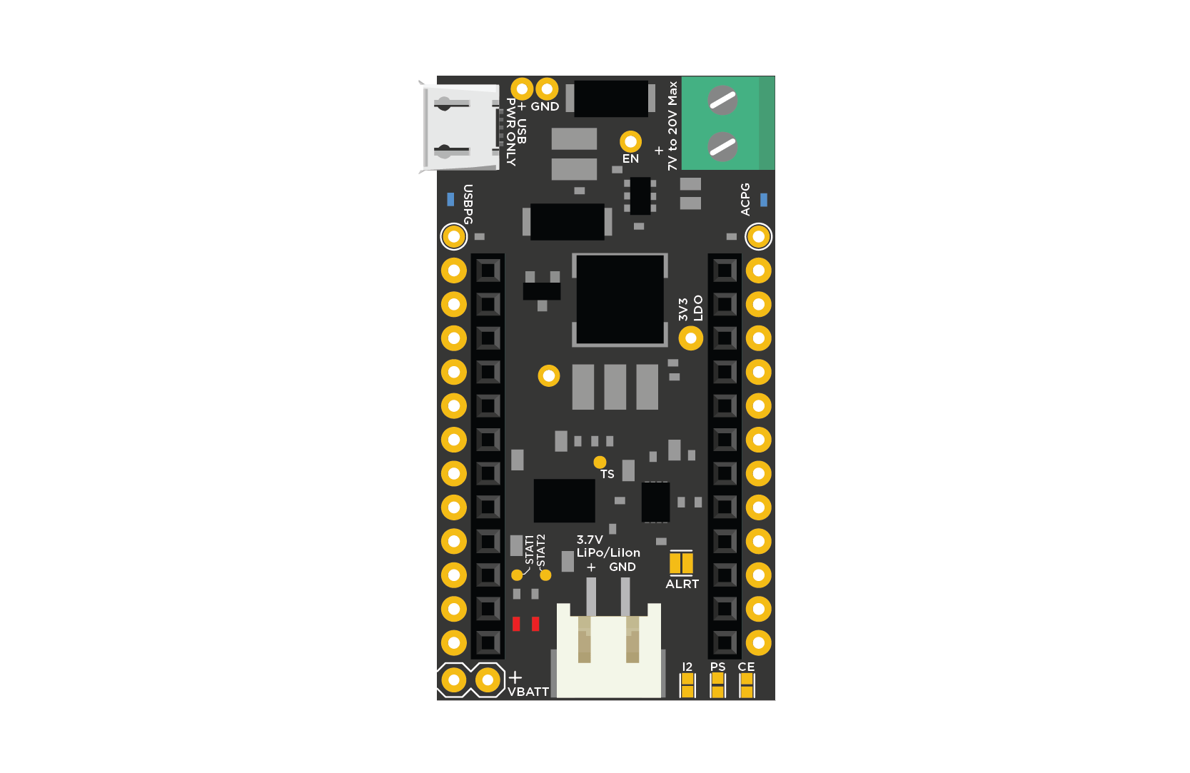
The system switches in between the different power sources automatically, reducing the charge and discharge cycle stress on the battery. The fuel gauge allows you to monitor the battery's state-of-charge (SOC), allowing it to notify the user remotely and take preemptive actions when necessary.
The shield is setup so that when powered from the USB port as well as from a DC supply, it chooses the DC source over USB. The charge current is set to 500mA when charging from USB and set to 1A when charging from a DC source.
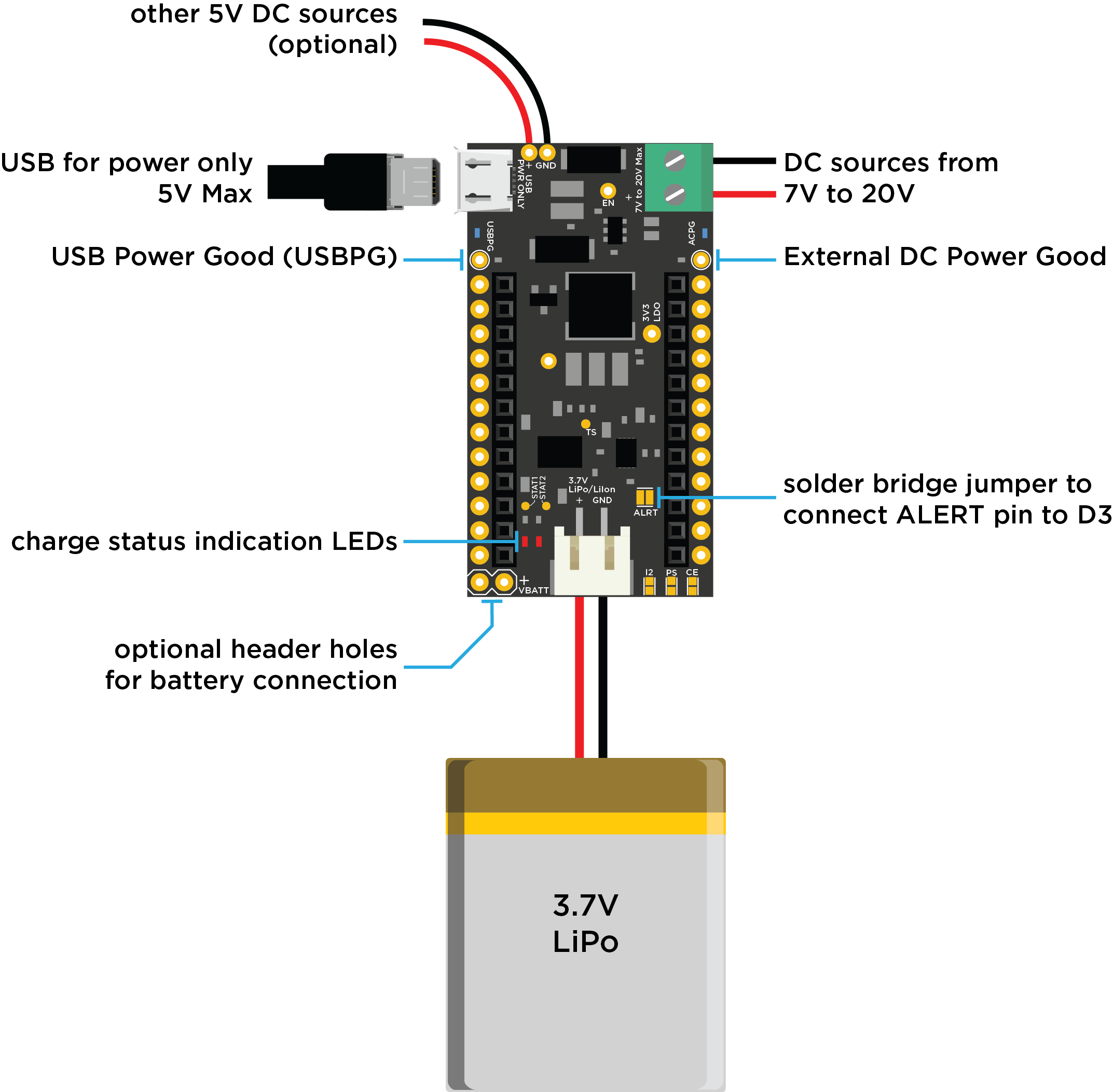
There are two status LEDs located on the left of the JST battery connector labeled STAT1 and STAT2. Here is a table of the LED behavior depending on which state the battery charger is in:
| STAT1 (Blue) | STAT2 (Red) | Charge State |
|---|---|---|
| ON | ON | Precharge in progress |
| ON | OFF | Fast charge in progress |
| OFF | ON | Charge done |
| OFF | OFF | Charge suspend (temperature), timer fault, and sleep mode |
The Power Shield includes a MAX17043 I2C fuel gauge chip to monitor the battery level. This is connected using the I2C interface, pins D0 and D1. You can still use the I2C interface in your design, however you should avoid using D0 and D1 as GPIO as it will interfere with the fuel gauge. The Power Shield includes the I2C pull-up resistors.
Power shield - specifications
- Operating voltage: USB or External DC of 7 to 20V
- Current consumption: 500mA max (USB) & 1.2A max (other DC sources)
Dimensions: 1" x 1.84"
NOTE: There is a know issue on the v2.1.0 of the Power Shield where the shield will fail to power up the Photon when the battery is inserted for the first time or reinserted after a long time (>60mins). The user will need to unplug and plug the battery back again for the shield to power up. The issue arises by the fact that on startup, the battery charger confuses the Photon booting up to there being a short circuit and powers off to save the device. If you are feeling adventurous, you can fix this issue by soldering a 10nF capacitor across the DPPM pin and GND. This delays the short-circuit protection at startup and lets the Photon bootup without any issues.
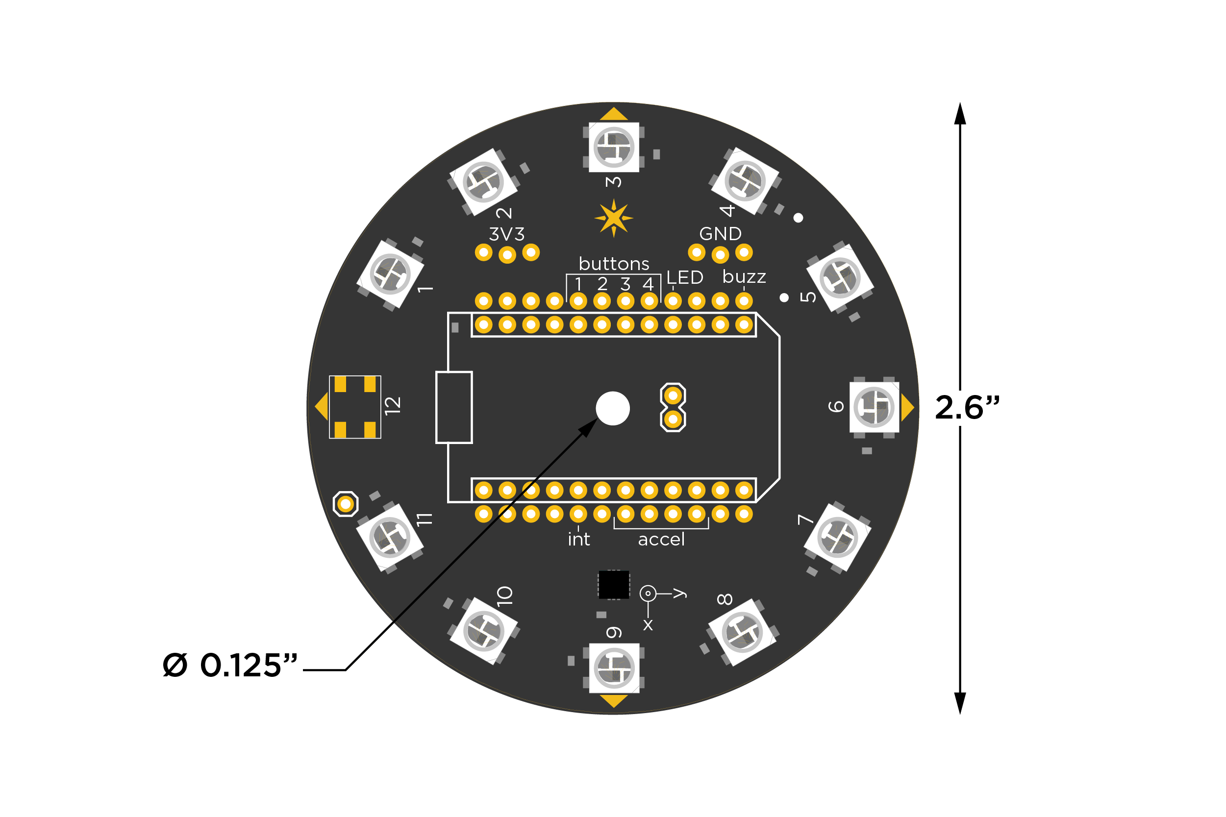
Internet button
The Internet Button is not only an easy way to get started on the Internet of Things, it's also a clean and simple way to start building your own prototypes. Quickly start playing with LEDs, multiple buttons, an accelerometer and more without any wires or soldering.
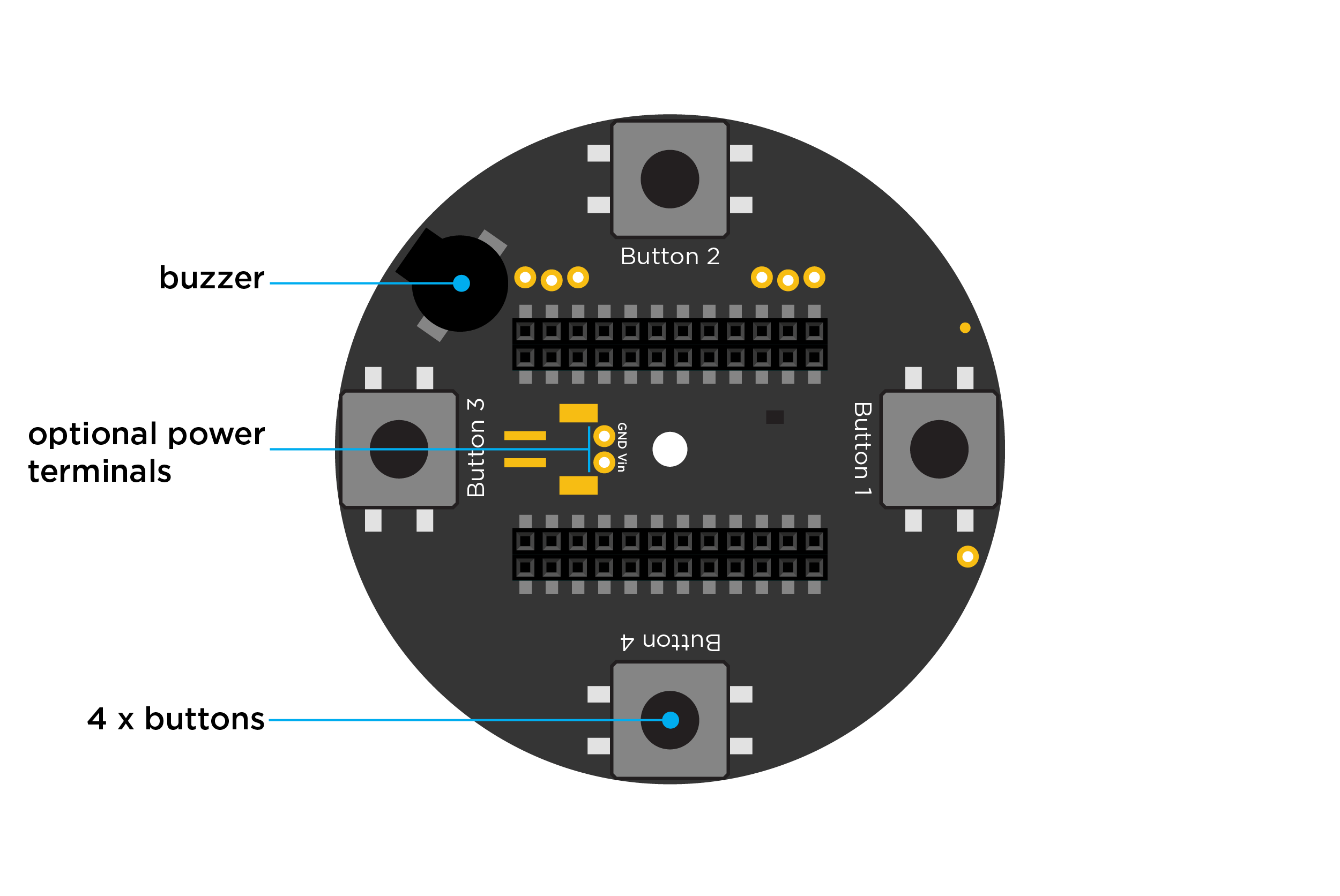
NOTE: There is a silkscreen issue with the current release of the Internet Button. On the PCB, the silkscreen labels are incorrect. The correct mapping is, from right to left, "1-2-3-4", not "4-3-2-1" as annotated on the PCB. For super double extra clarity, please see the following pin mapping label table:
| Photon Pin | Correct Mapping | Incorrect Mapping |
|---|---|---|
| D4 | Button 1 | Button 4 |
| D5 | Button 2 | Button 3 |
| D6 | Button 3 | Button 2 |
| D7 | Button 4 | Button 1 |
Internet button - library
If you're already logged into Build.particle.io then you can jump directly to the library to get going quickly and easily with the InternetButton library, which wraps all the features in easy-to-use functions.
Examples include:
- Blink an LED - How to control the smart LEDs on this board
- Blink all the LEDs - An extension on the simplest case
- LEDs and Buttons - How to read the buttons on the Button, and make LEDs blink with them
- Good Combination - A set of button and LED conditionals that I happen to like and use frequently
- Motion - The Internet Button also has an accelerometer on it to measure motion- this shows how the related functions work
- Orientation - How to use the accelerometer functions to determine the orientation
- Internet - Send that data out to the world!
- Making Music - Learn how to play notes and songs with your Button
- Release Firmware - Big, complicated set of epic.
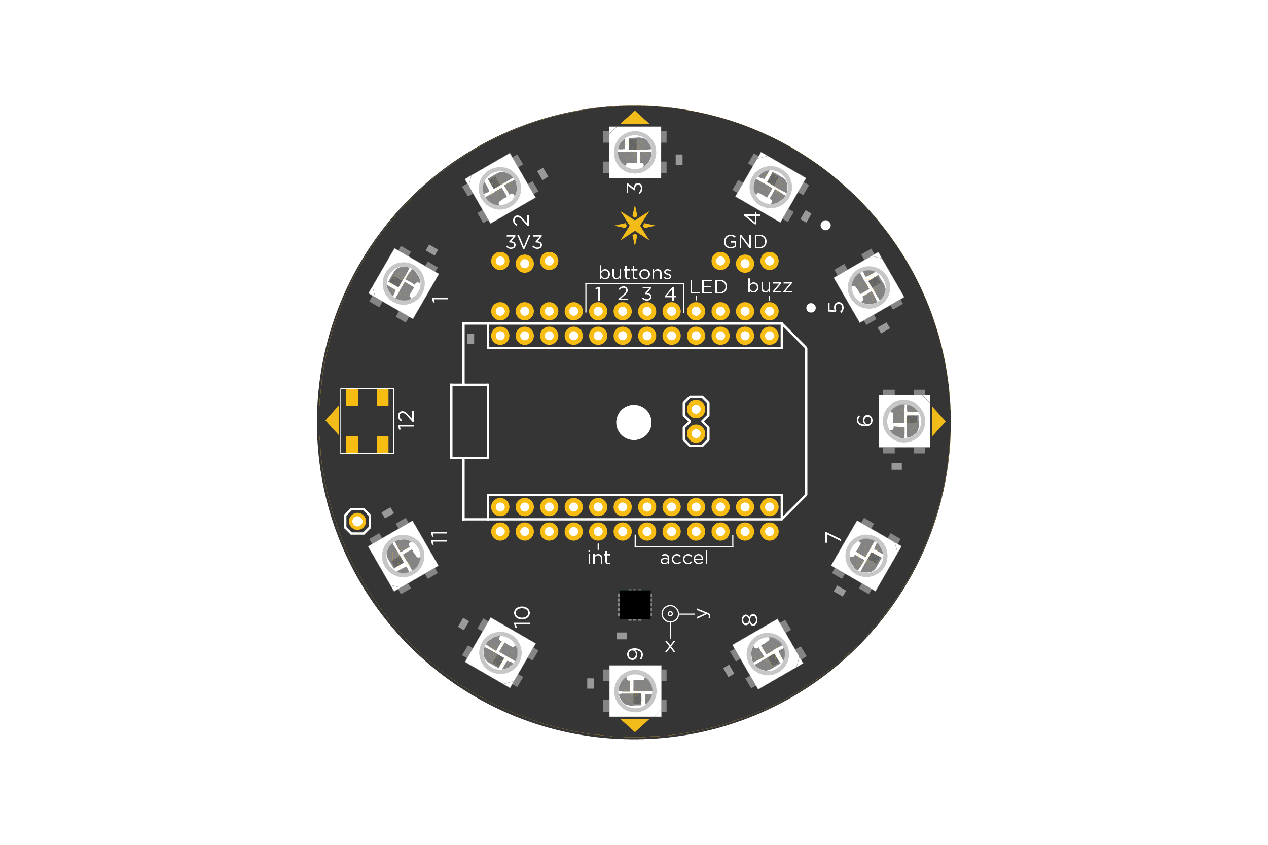
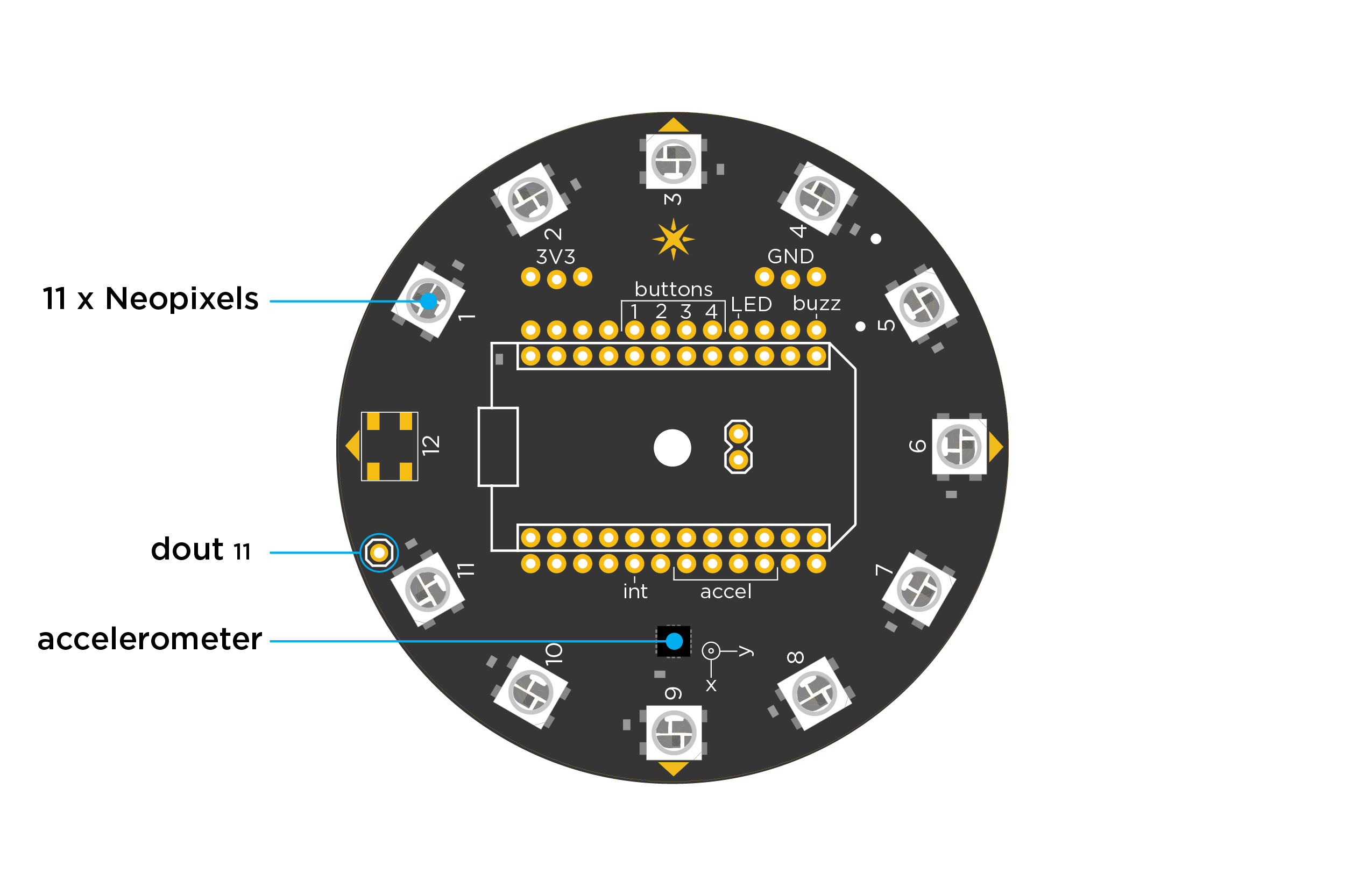
Internet button - top
Internet button - bottom
Internet button - specifications
- Operating voltage: USB or External DC of 3.3 to 5.5VDC
- Dimensions: 2.6" x 2.6"
- 11 individually controllable RGB LEDs
- ADXL362 3-axis accelerometer
- 4 tactile buttons for D-pad style interactions
- Female socket for connection to a Particle device
- Additional female headers for adding extra actuators and sensors
- Backward compatible with the Core
Photon Kit
Photo sensor (1)
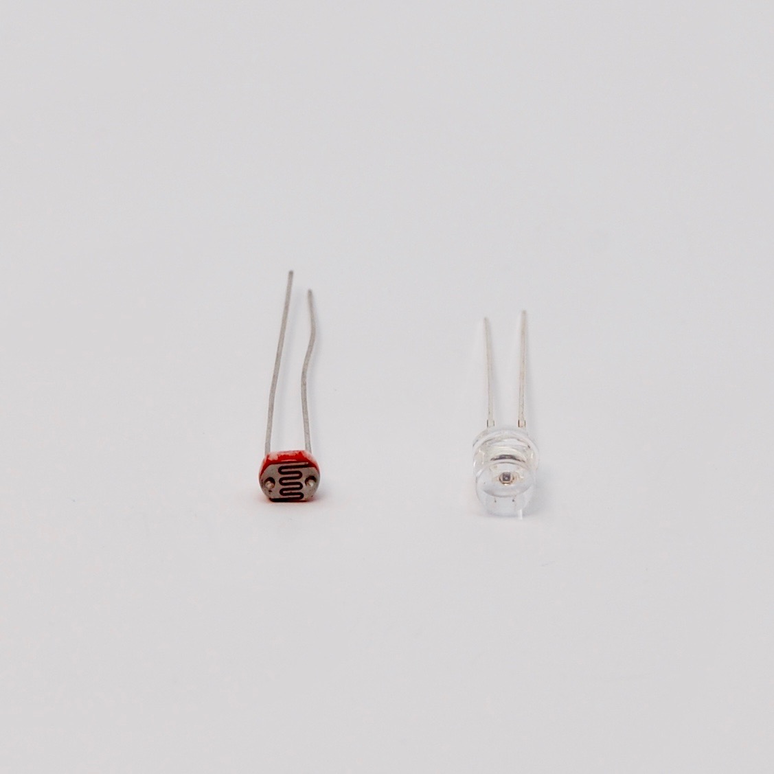
Your kit will come with either a photo resistor (left) or a photo transistor (right).
The circuits for using them vary slightly but both output a signal that varies depending on the intensity of light striking them. You can use them to detect the ambient light in the surrounding, detect shadows, or use them as a part of a burglar alarm system.
The cadmium sulfide (CdS) photo resistor was removed from newer kits because of RoHS restrictions on the use of cadmium.
LED (1)
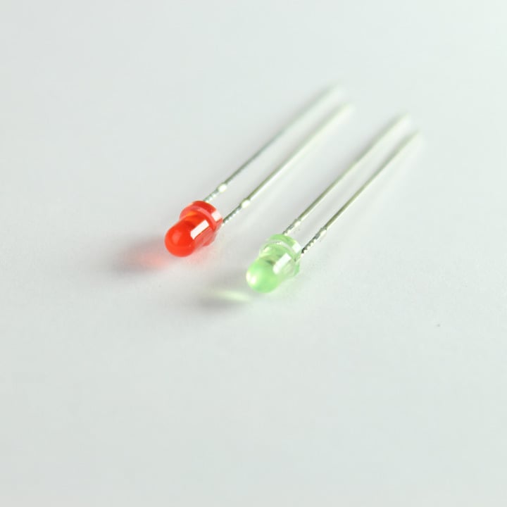
This general purpose 3mm red LED is great for getting started with your Photon. You can never have enough of them!
Resistors (2)
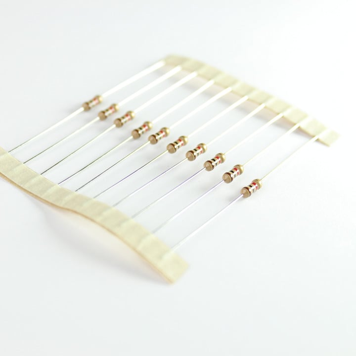
You get two 220-Ohm resistors in your Photon Kit. They are rated at 5%, 1/4 Watt.
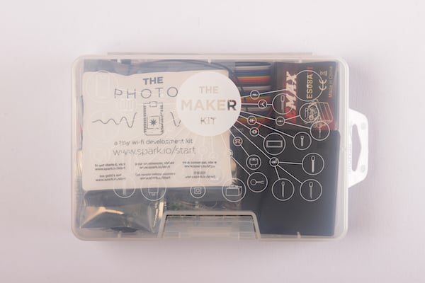
Photon maker kit contents
Photon with Headers (1)
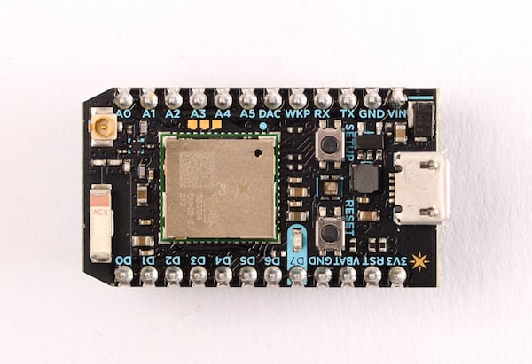 Click here for the Photon datasheet
USB Micro B cable (1)
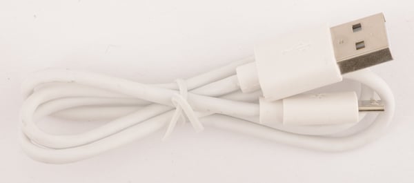
A custom Particle USB cable for your Photon! We were really excited to have our logo printed on them :)
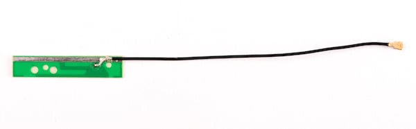
Flex antenna (1)
Mini breadboard (1)
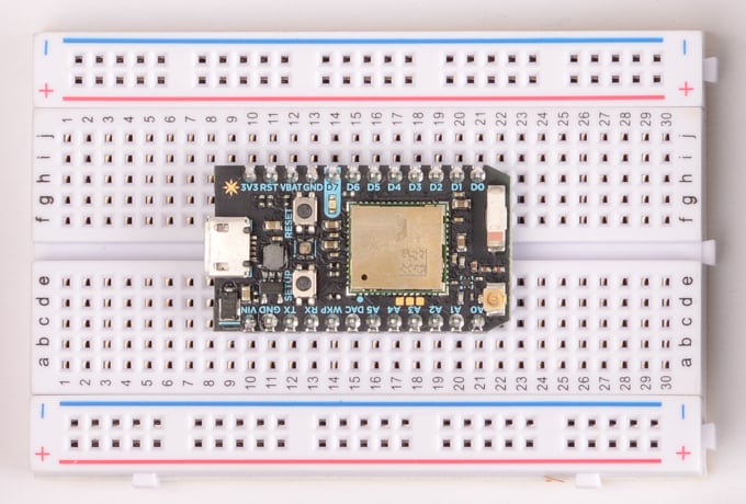
This breadboard is pictured with a Photon in it.
Proto-board (1)
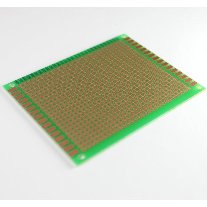
This is a 7" x 9" general purpose dot-matrix prototyping PCB.
Deluxe jumper wire pack (1)
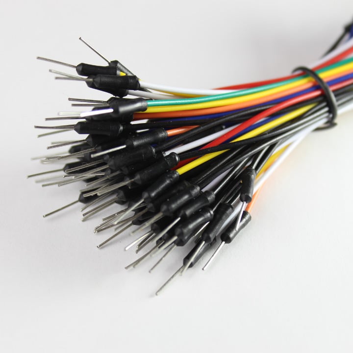
Multi-colored and stripped. You can never have enough of these either.
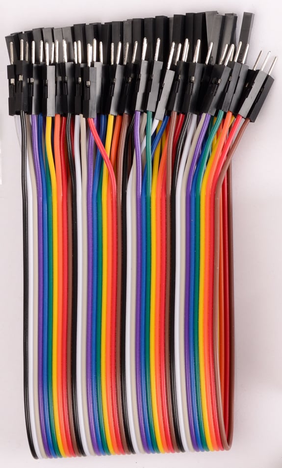
Male to female jumper wires (10)
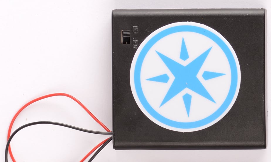
Battery holder - 4xAA (1)
Headers (7)
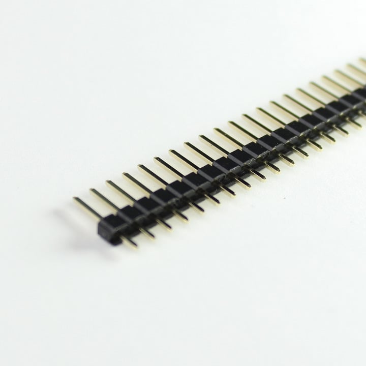
These are standard 0.1" pitch headers that can be cut to size. Very handy when building circuits on breadboard or PCBs alike.
- 12-Pin Female Headers (5)
- 40-Pin Male Breakaway Headers (2)
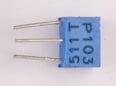
Ceramic capacitors (10 each)
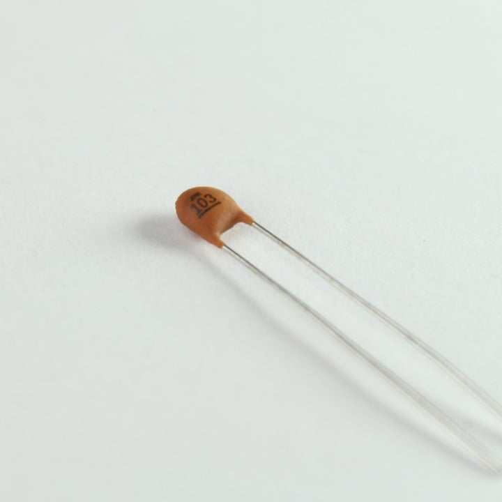
These are standard ceramic capacitors. They are widely used in analog circuits as bypass/ decoupling capacitors, in timers, filters, etc. The kit comes with:
- 10nF (0.01uF) - Number code: 103
- 100nF (0.1uF) - Number code: 104
Note: These are non-polar capacitors which means they can be oriented both ways.
Electrolytic capacitor 100uF (5)
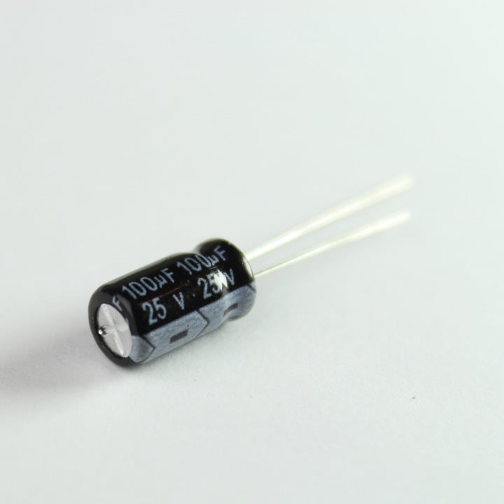
Electrolytic capacitors offer larger values and are polar. These capacitors are ideal for decoupling power supplies, as transient suppressors, and in timing circuits.
Note: These are polar capacitors. The longer lead denotes positive while the shorter one denotes negative. These are also know to "pop" when subjected to voltages higher than their ratings.
LEDs (10)
These are general purpose 3mm LEDs. You can never have enough of them! Use a resistor in series when hooking them up to the Particle device. ( 220 ohms to 1K ohms)
- Red (5)
- Green (5)
Note: The longer lead is positive (anode) while the shorter one is negative (cathode).
RGB LED (1)
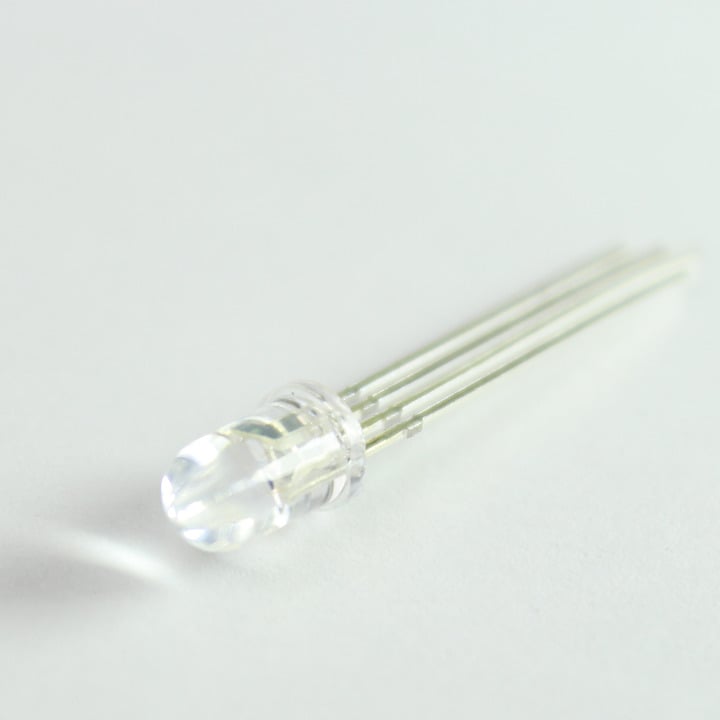
So, Red and Green aren't enough for you? Want to make bazzillion different colors? Then this RGB LED will do it for ya. You can mix colors by connecting each pin to an analogWrite compatible pin on the Core and feed them different values. Let the disco party begin!
This LED has four pins, one for each color and a common anode (+) pin.
Diode (6)
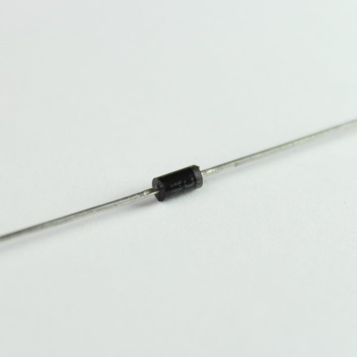
1N4004 is a general purpose diode rated at 400V, 1000mA with a forward voltage drop of 1.1V. Excellent as a fly-back diode or as a general rectifying diode.
IR LED (1)

You can take control of your television, air-conditioner or any other IR remote controlled devices with this IR LED. Simply connect it to the Particle device with a series 220 ohm resistor, use the appropriate IR code library, and control things over the Internet!
Specifications:
- Continuous forward current: 100mA (1A peak)
- Power dissipation: 150mW
- Peak wavelength: 940nm
- View angle: 20 deg
Resistors (30)
There are three different value resistor in this kit. All of them are rated at 5%, 1/4 Watt.
- 220-Ohm (10)
- 1K-Ohm (10)
- 10K-Ohm (10)
You can use this online guide to help identify which resistor is which value.
Photo sensor (2)
Your kit will come with either a photo resistor (left) or a photo transistor (right).
The circuits for using them vary slightly but both output a signal that varies depending on the intensity of light striking them. You can use them to detect the ambient light in the surrounding, detect shadows, or use them as a part of a burglar alarm system.
The cadmium sulfide (CdS) photo resistor was removed from newer kits because of RoHS restrictions on the use of cadmium.
10K rotary potentiometer (1)
Temperature sensor (1)
The DS18B20 is an easy to use one wire digital thermometer with up to 12-bit measuring resolution.
- Supply Voltage: 3.0V to 5.5V DC
- Current consumption: 4mA max
- Measuring temperature range: -55°C to +125°C
- Accuracy: ±0.5°C (from -10°C to +85°C)
- Package: TO-92
Temperature sensor - sealed (1)
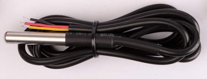
This is the sealed, water proof version of the DS18B20 temperature sensor with wires.
- Red: 3.3V to 5.0V
- Yellow: Sensor output (1-Wire)
- Black: Ground
Piezo buzzer (1)
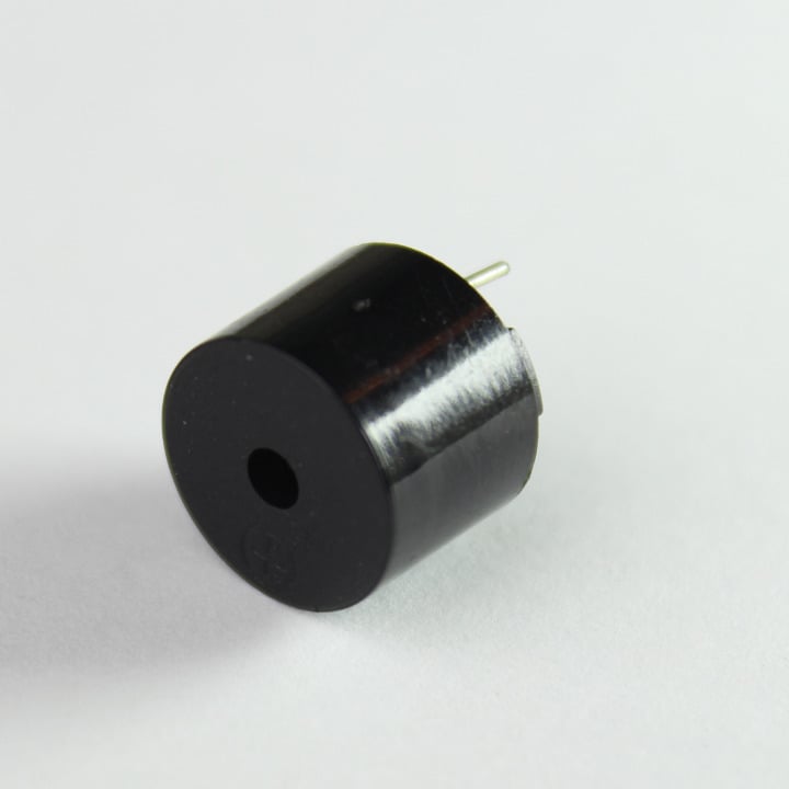
Add an audible feedback to your project with this buzzer. The longer lead is positive and the shorter is negative. You will need a transistor to drive it.
Note: The sound gets annoying after a while. Use it sparingly!
- Operating Voltage: 4.0 to 7.0 V DC
- Oscillation Frequency: 2.3KHz
- Current: 30mA
- Sound Pressure: 85dB
Mini push buttons (3)
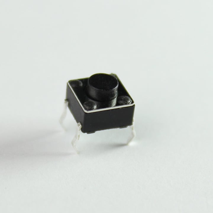
These are nifty little switches that plug nicely into a breadboard or a proto-board. They are normally-open type and are rated at 12V, 50mA.
SPDT Switch (2)
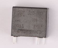
SPDT Relay (1)
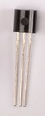
NPN Transistor (1)
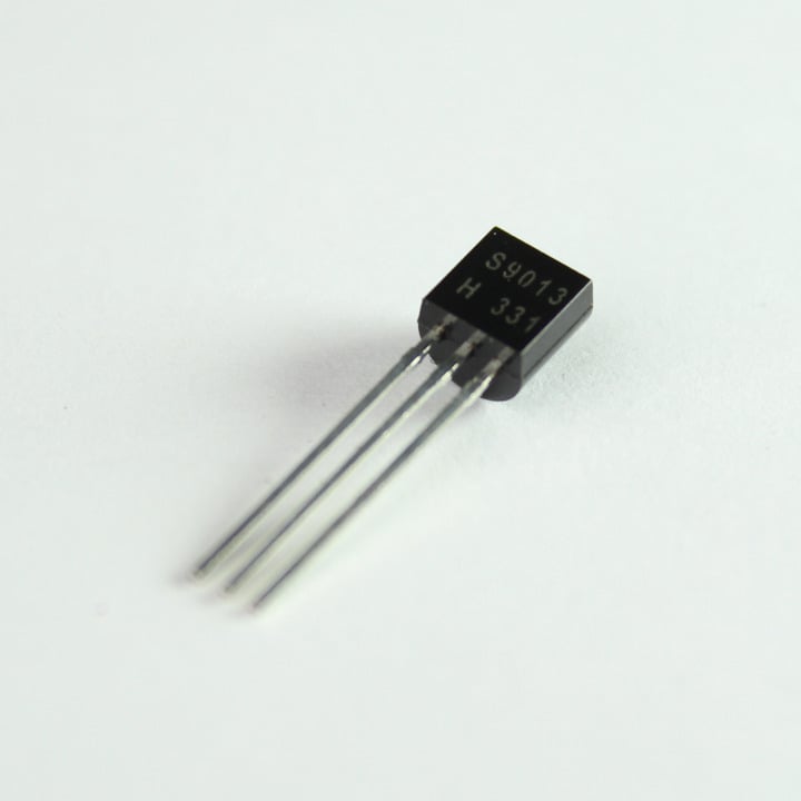
S9013 is a general purpose small signal NPN transistor rated at 40V, 500mA.
You can use this transistor to switch small loads like relays, mini motors, buzzers, etc.
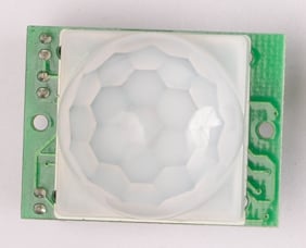
PIR sensor (1)
Pancake vibration motor (1)
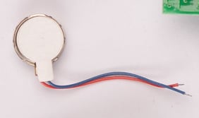
Wanna give your next Particle device project a tactile feedback? This vibration motor serves the purpose nicely. Use the NPN transistor to switch it.
Micro servo (1)
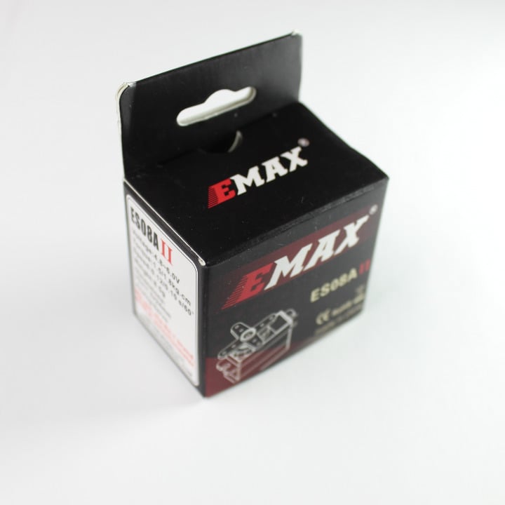
Emax ES08A is a mini RC servo motor.
- Operating Voltage: 4.8 to 6.0VDC
- Stall Torque: 1.8Kg/cm
- Speed: 0.10sec/degree at no load
Wiring:
- Yellow - Signal (D0, D1, A0, A1, A4, A5, A6, A7)
- Orange - +5V (VIN)
- Brown - Ground (GND)
Note: The Ground pin may vary as Brown or Black, +5V pin may vary as Orange or Red and Signal pin may vary as Yellow or White and sometimes Orange if there is already a Red and Black wire.
Serial OLED screen,0.96"(1)
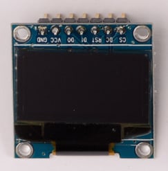
This is a 128x64 pixel graphic OLED screen that can be either controlled via the SPI (default) or I2C.
Sample code
- Adafruit SSD1306 in the Particle Web IDE Library
- https://github.com/pkourany/Adafruit_SSD1306
Specifications:
- Supply Voltage: 3.0V to 5V DC
- Current consumption: 50mA max
- Communication modes: SPI or I2C
Electron solar kit
The Electron Solar Kit has been discontinued and is no longer available.
The Solar Kit comes with everything you need to make a solar powered cellular project! Super efficient power design so you can go off-the-grid with no need of wires. It has a big 6W solar panel, waterproof enclosure with cable gland for connecting the panel, and a super low-power timing circuit so the Electron can sleep in between readings. It's an ideal solution for field sensing that needs to go on for months or years.
Using the solar kit
Assembly:
- Screw the cable gland into the side of the box. If you want it to be truly water-tight, you should add some silicone caulk. Also, the inner nut may not have enough clearance to fit, but that's fine with caulking.
- Screw the Solar Shield down inside the box using the included M4 screws.
- Pass the barrel jack wire through the cable gland, leaving the bare wires inside the box and the connector outside.
- Put the red wire into the terminal block marked "+" and the black wire into "GND" and tighten them down firmly with a small screwdriver.
- Tighten the cable gland around the barrel jack wire,
- Plug the Electron into the shield with the USB pointing inward
- Connect the male JST wire from the shield to the female JST on the Electron
- Plug the battery into the Solar Shield's female JST
- Connect the solar panel to the barrel jack. This may take a little force to get secure.
Note: The lid has small plastic "keys" that will only allow it to be screwed down securely in one orientation. Look for them at the outer corners right next to the screw holes
Recommended operating conditions
| Parameter | Symbol | Min | Typ | Max | Unit |
|---|---|---|---|---|---|
| Solar Input Voltage | VIN | +4.95[1] | +32 | V | |
| Supply Output Voltage | V3V3 | +3.3 | V | ||
| LiPo Battery Voltage | VLiPo | +3.6 | +4.4 | V | |
| Deep Sleep Current (4.2V LiPo) | IQds | 5 | 10 | uA | |
| Operating Temperature | Top | -20 | +60 | °C | |
| Humidity Range Non condensing, relative humidity | 95 | % |
Electron Asset Tracker
![]()
The Electron AssetTracker has been deprecated. You can continue to use your Electron AssetTracker, but new units will not be manufactured and it will likely not have future software updates.
The Electron Asset Tracker is a cellular solution for tracking the location of just about anything! The included shield has a GPS module and an accelerometer, so you can make projects that use location, orientation, and movement. Report vibration as you drive around, save power by keeping the cell modem and GPS off if the device isn't moving, or track boxes. Also has a screw terminal for adding another power source and a connector for adding an external GPS antenna if it's going to be inside something. Designed by Adafruit!
Using the Electron Asset Tracker
![]()
Power
There are a couple of different ways that you can power this shield. You can power it via the screw terminal from a 5V to 12V DC supply (make sure it can support at least 2 Amp current peaks) or you can simply power it via the LiPo battery that came with the Electron. You can also use the two sources together. We do not recommend powering it from a USB source, as the USB cable will block the GPS module leading to a poor or no satellite reception. If you HAVE to use the USB power, then make sure to use an external GPS antenna.
Remember that in order for the battery to last a long time, it's ideal that you put the Electron in deep sleep mode and turn off the GPS when not needed. This is described in greater detail under the library section.
While the screw terminal input allows up to 12 VDC we don't recommend connecting it directly to an automobile electrical system without additional protective circuits. There are often voltage spikes that can damage the Electron power supply. Two good references are the ST Microelectronics AN2689 "Protection of automotive electronics from electrical hazards, guidelines for design and component selection" and the OpenXC power supply design.
Your asset tracker has emotions too. Don't make it sad. Don't be that person.
GPS
The shield has the same GPS module as the Adafruit Ultimate GPS so all of their specs and usage notes apply here, too. It's the PA6H module based around the Mediatek's MT3339 GPS receiver.
The primary bit to know is that the GPS module can take several minutes to get a lock, and may not get a lock at all if it doesn't have a clear view of the sky- sorry, no indoors projects. If this is proving a problem for you, an external antenna may help (don't forget an SMA to uFL adapter!).
When the GPS Fix LED is blinking once per second (1Hz) then it is trying to get a fix but does not yet have one. It will turn OFF when it actively has a fix, and you can check that from code using the .gpsFix() function.
The GPS is connected to the Serial1 UART on the Electron, and we've also provided a MOSFET to completely shut off power to it for major power savings. Pin D6 controls the GPS power, with inverted logic. This means that the GPS will only be ON when D6 is LOW, which should keep it off even if you put the Electron to sleep.
Backup battery
There's a backup battery holder for the GPS to reduce subsequent fix acquisition times, but it's not required. This is the small coin cell (part number CR1220) holder slot. Inserting the coin cell powers up the internal RTC of the GPS module and also help retain the satellite data in its volatile RAM. It is highly recommended that you have this battery plugged in at all times to bring down fix times.
Accelerometer
The shield also has an on-board accelerometer, the LIS3DH. It's extremely low power so won't chew up your energy budget. The accel communicates over SPI, so it takes up A2, A3, A4, and A5 as marked on the silkscreen of the shield. A configurable interrupt from the LIS3DH is connected to the Electron's "wake" (WKP) pin, so you should be able to make a project where the Electron and GPS stay in deep sleep until it's hit hard enough to cross a threshold you set on the accelerometer.
Enclosure
The waterproof box includes two M4 screws for mounting the shield securely into the box. Screw the shield down in the enclosure, then plug the Electron into the shield with the USB connector facing inward. You can also look at the silkscreen Electron outline on the board for the correct orientation. The battery and antenna can be fixed in the box using the foam adhesive tape if you want to keep them from moving around.
Asset tracker library
We've put together a great library for you to start building from! If you're already logged into the Web IDE then you can just click on AssetTracker library and you can always open the "Libraries" view in the Web IDE, and AssetTracker will show up under the Official Libraries. This library is especially good for learning about the Electron because it implements a couple of useful features, like a Particle.function for checking the battery level!
Examples:
- GPS Features - How to use the GPS efficiently, and some nice Electron functions
- Accelerometer - Using the accelerometer with some cute tricks
GPS module specifications
- 22 Tracking/ 66 acquisition channels
- Update rate: 1Hz (default), 10Hz (max)
- Position accuracy: 2.5 to 3.0 meters
- Altitude: 18000m (max)
- Velocity: 515m/s (max)
- Velocity accuracy: 0.05 to 0.1m/s
- Acceleration: 4G (max)
- Frequency: L1, 1575.42MHz
- Supports up to 210 PRN channels
- Supports multi-GNSS incl. QZSS, SBAS ranging
- Supports WAAS/EGNOS/MSAS/GAGAN
- NMEA 0183 standard v3.01 and backwards compatible
Recommended operating conditions
| Parameter | Symbol | Min | Typ | Max | Unit |
|---|---|---|---|---|---|
| Supply Input Voltage | VIN | +5.0[1] | +12 | V | |
| Supply Output Voltage | V3V3 | +3.3 | V | ||
| LiPo Battery Voltage | VLiPo | +3.6 | +4.4 | V | |
| Backup power consumption at 3V (GPS only) | IQs | 7 | uA | ||
| Deep Sleep Current (4.2V LiPo) | IQds | 120 | 140 | uA | |
| Operating Temperature | Top | -20 | +60 | °C | |
| Humidity Range Non condensing, relative humidity | 95 | % |
Shield specifications
![]()
Hardware revision history
| Revision | Date | Author | Comments |
|---|---|---|---|
| v001 | 20-Jan-2016 | MB | Initial release |
| v002 | TBD | TBD | TBD |
Known hardware issues
| Revision | Date | Author | Comments |
|---|---|---|---|
| v001 | 20-Jan-2016 | MB | The TX and RX labels are flipped on the PCB. USB cable blocks the GPS antenna when powering over USB. |
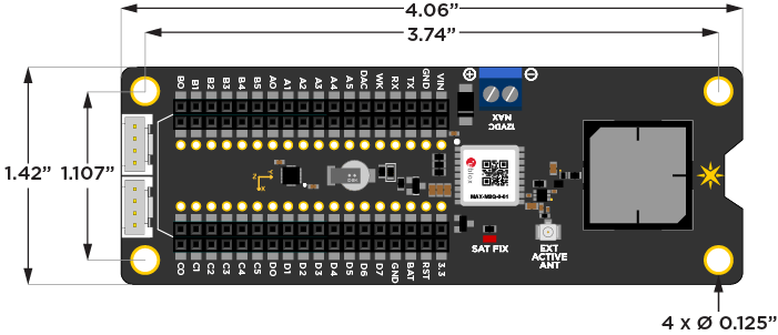
Electron Asset Tracker v2
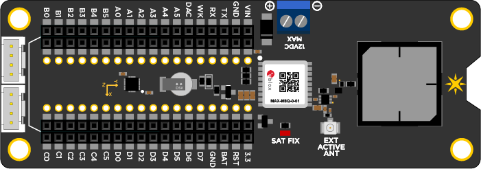
The Electron AssetTracker v2 has been deprecated. You can continue to use your Electron AssetTracker, but new units will not be manufactured and it will likely not have future software updates.
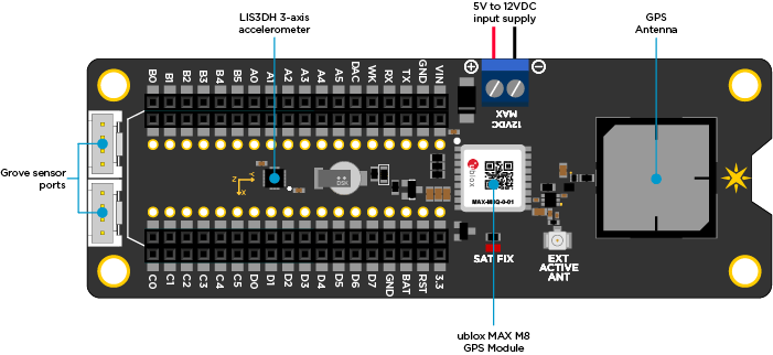
This new revision of the Electron Asset Tracker uses a u-blox M8 engine GNSS receiver. Unlike the v1, this module is capable of receiving 3 GNSS (GPS, Galileo, GLONASS, BeiDou) concurrently. We have also added a low noise amplifier and a band pass filter for improved performance with the on-board antenna.
Using the Electron Asset Tracker
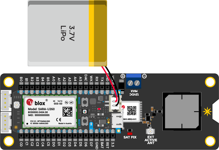
Power
There are a couple of different ways that you can power this shield. You can power it via the screw terminal from a 5V to 12V DC supply (make sure it can support at least 2 Amp current peaks) or you can simply power it via the LiPo battery that came with the Electron. You can also use the two sources together. We do not recommend powering it from a USB source, as the USB cable will block the GPS antenna leading to a poor or no satellite reception. If you HAVE to use the USB power, then make sure to use an external GPS antenna.
Remember that in order for the battery to last a long time, it's ideal that you put the Electron in deep sleep mode and turn off the GPS when not needed. This is described in greater detail under the library section.
While the screw terminal input allows up to 12 VDC we don't recommend connecting it directly to an automobile electrical system without additional protective circuits. There are often voltage spikes that can damage the Electron power supply. Two good references are the ST Microelectronics AN2689 "Protection of automotive electronics from electrical hazards, guidelines for design and component selection" and the OpenXC power supply design.
GPS
The GPS is connected to the Serial1 UART on the Electron, and we've also provided a MOSFET to completely shut off power to it for major power savings. Pin D6 controls the GPS power, with inverted logic. This means that the GPS will only be ON when D6 is LOW, which should keep it off even if you put the Electron to sleep.
When the module acquires a satellite fix, the SAT FIX LED on the shield will start blinking at the rate of once per second. The acquisition time can vary anywhere from 26 seconds, from a cold start, to around 1 second from a hot restart.
Backup Power
The shield has a super capacitor connected to the back up power of the GPS receiver. This helps the receiver retain time and satellite fix information upon a power cycle. The capacitor should be able to provide backup power for a few minutes after you remove the main supply. This is helpful when you are changing batteries or plugging/unplugging the Electron. For longer backup times, we have provided a footprint to solder in a CR2032 coin cell holder at the bottom. In most cases, you will not need it.
Accelerometer
The shield also has an on-board accelerometer, the LIS3DH. It's extremely low power so won't chew up your energy budget. The accel communicates over SPI, so it takes up A2, A3, A4, and A5 as marked on the silkscreen of the shield. A configurable interrupt from the LIS3DH is connected to the Electron's "wake" (WKP) pin, so you should be able to make a project where the Electron and GPS stay in deep sleep until it's hit hard enough to cross a threshold you set on the accelerometer.
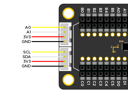
Grove Sensor Ports
We have provided two grove sensor ports for you to easily connect sensors to the asset tracker. One of the connector exposes the I2C port (D0 and D1), while the other exposes two analog pins (A0 and A1).
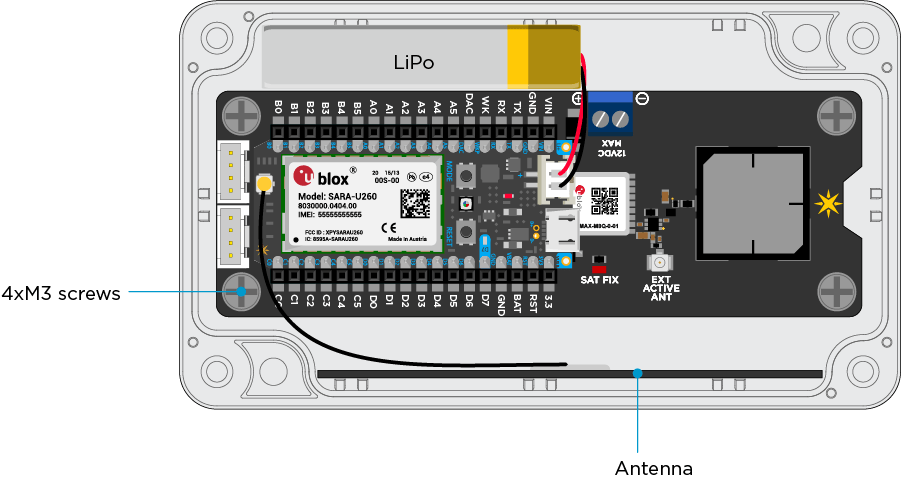
Enclosure
You can choose to mount the asset tracker board inside the provided enclosure as shown below. Use the four M3 screws to secure the board in place. The antenna comes with a peel-able sticky back that can be used to stick the antenna to the side wall. Remember not to block the GPS antenna with anything - wires, antenna, battery, etc. Enclosure dimensions are: 115.06 x 65.02 x 39.88 mm.
Electron Asset Tracker library
We've put together a great library for you to start building from! If you're already logged into the Web IDE then you can just click on AssetTracker library and you can always open the "Libraries" view in the Web IDE, and AssetTracker will show up under the Official Libraries. This library is especially good for learning about the Electron because it implements a couple of useful features, like a Particle.function for checking the battery level!
Examples:
- GPS Features - How to use the GPS efficiently, and some nice Electron functions
- Accelerometer - Using the accelerometer with some cute tricks
Specifications
- 72-channel u-blox M8 engine
- GPS/QZSS L1 C/A, GLONASS L10F, BeiDou B1I, Galileo E1B/C, SBAS L1 C/A: WAAS, EGNOS, MSAS, GAGAN
- Update rates: Single GNSS: up to 18 Hz, 2 Concurrent GNSS: up to 10 Hz
- Position accuracy of 2.5 m
- Sensitivity of -167 dBm
- Acquisition times: Cold starts: 26s, Aided starts: 2s, Reacquisition: 1s
- Onboard ROM
- Anti spoofing and anti jamming technologies
- Operating temperature of –40° C to 85° C
Recommended operating conditions
| Parameter | Symbol | Min | Typ | Max | Unit |
|---|---|---|---|---|---|
| Supply Input Voltage | VIN | +5.0[1] | +12 | V | |
| Supply Output Voltage | V3V3 | +3.3 | V | ||
| LiPo Battery Voltage | VLiPo | +3.6 | +4.4 | V | |
| Current consumption at 3V (GPS only) | I | 6.2 | 67 | mA | |
| Total current consumption | I | 50 | 800 | mA | |
| Backup power consumption at 3V (GPS only) | IQs | 15 | uA | ||
| Deep Sleep Current (4.2V LiPo) | IQds | 120 | 140 | uA | |
| Operating Temperature | Top | -40 | +85 | °C | |
| Humidity Range Non condensing, relative humidity | 95 | % |
Electron sensor kit
This is the big one! A fantastic collection of premium and versatile sensors.
Sensor kit includes
- (1) Electron
- (1) USB Micro B Cable
- (1) Particle SIM Card
- (1) Cellular Antenna
- (1) 1,800mAh LiPo Battery
- (1) Particle Sticker
- (2) Resistor 220-Ohm
- (1) Breadboard
- (1) Photo resistor or photo transistor
- (1) White or red LED
AND
- (1) ADXL362 accelerometer
- (1) GP2Y0A710K0F 100-550cm IR Distance sensor
- (1) Loudness sensor with LM2904 opamp
- (1) MQ2 gas sensor for LPG, i-butane, propane, methane, alcohol, hydrogen and smoke.
- (1) SHT10 soil humidity and temperature sensor
(1) HC-SR501 PIR motion sensor
(1) DS18B20 waterproof temperature sensor
- (1) SW18020P vibration sensor
- Various jumper wires, resistors, capacitors, LEDs, and push buttons
Your kit will come with either a photo resistor (left) or a photo transistor (right).
The circuits for using them vary slightly but both output a signal that varies depending on the intensity of light striking them. You can use them to detect the ambient light in the surrounding, detect shadows, or use them as a part of a burglar alarm system.
The cadmium sulfide (CdS) photo resistor was removed from newer kits because of RoHS restrictions on the use of cadmium.

Your kit may include a variety of similar looking components:
- IR LED (blue-ish)
- White LED (clear with rounded top)
- Red LED (included with most kits that contain a photo transistor instead of the white LED to reduce confusion)
- Photo transistor (clear and flat on top)