
Tracker M datasheet
Pre-release draft 2022-10-27 for review only. Do not distribute or share this URL!
This is an preliminary pre-release datasheet and the contents are subject to change. The Tracker M design has not been finalized so changes are likely.
The Tracker M will typically be used as a complete off-the-shelf design, like the Tracker One, particularly in micromobility and light electric vehicle applications. Unlike the Tracker One, it is a miniaturized set of circuit boards that are designed fit within your existing equipment enclosures.
Block diagram
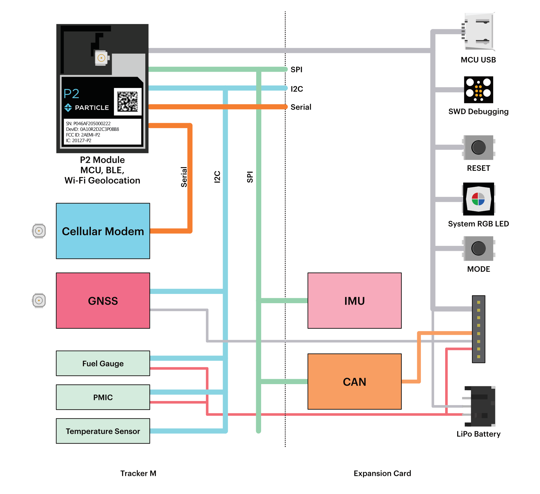
The Tracker M module contains the following functional units:
- P2 module (MCU, BLE, and Wi-Fi geolocation)
- Cellular modem
- GNSS (GPS)
- Fuel gauge (battery level monitoring)
- PMIC (Power Management IC and charge controller)
- Temperature sensor
In most cases, you will use the standard expansion card which contains:
- IMU (accelerometer)
- CAN controller, transceiver, and protection circuity
- MCU USB connector, for development and debugging
- SWD debugging, for debugging and optionally for factory firmware flashing
- RESET and MODE buttons
- System RGB LED for troubleshooting
- LiPo battery connector with battery thermistor
- On-board GNSS antenna (optional)
- External connections (listed below)
The following antennas are available
- Cellular (LTE)
- GNSS (dual band, can be mounted on the expansion card, or external)
- Wi-Fi geolocation and BLE
MCU
The P2 is a SMD module with a microcontroller, 2.4 GHz and 5 GHz Wi-Fi, and BLE.
- 802.11a/b/g/n Wi-Fi, 2.4 GHz and 5 GHz
- Integrated PCB antenna
- Integrated U.FL connector for external antenna
- Integrated RF switch
- BLE 5 using same antenna as Wi-Fi
- Realtek RTL8721DM MCU
- ARM Cortex M33 CPU, 200 MHz
- 2048 KB (2 MB) user application maximum size
- 3072 KB (3 MB) of RAM available to user applications
- 2 MB flash file system
- FCC, IC, and CE certified
Interfaces
External connection - CAN expansion card
The Tracker M is intended to connect to your equipment from the expansion card.
On the CAN expansion card, this is done using solder pads:
| Name | Description |
|---|---|
| VIN | 6 to 90 VDC |
| GND | Ground |
| CAN+ | CAN interface (+, P, or H) |
| CAN- | CAN interface (-, N, or L) |
| TXD | Serial1 TX (transmitted data), GPIO |
| RXD | Serial1 RX (received data), GPIO |
| TS | Battery thermistor |
| LI+ | LiPo battery |
| GND | Ground |
| D10 | Wake interrupt (active low, open-collector) |
| A1 | A2 Analog in, PWM, GPIO |
| GND | Ground |
Power is supplied by GND and VIN, from 6 to 90 VDC. It is acceptable to connect it directly to a vehicle power supply with no additional conditioning.
The CAN (controller access network) interface can interact with other equipment with a CAN interface, or an engine control unit (ECU).
Expansion card
In most cases, you will use the standard expansion card. It is also possible to develop your own expansion card.
The connectors on the Tracker M module are:
| Description | |
|---|---|
| Manufacturer | Hirose Electric Co. Ltd. |
| Part Number | DF40C-60DP-0.4V(51) |
| Description | 60 Position Connector Plug, Outer Shroud Contacts Surface Mount Gold |
Note that the Tracker M is intended to be mounted on the bottom side of the expansion card, so the expansion card faces up and the Tracker M is on the bottom.
GPIO
| Pin Name | Description | SoM Pin | MCU |
|---|---|---|---|
| CAN_STBY | CAN_STBY, IOEX GPB1 | ||
| CAN_VDD_EN | CAN_VDD_EN, CAN 5V supply enableIOEX GPB0 | ||
| P2_A0 / D11 | A0 Analog in, GPIO | PB[1] | |
| P2_A1 / D12 | A1 Analog in, GPIO | PB[2] | |
| P2_A2 / D13 | A2 Analog in, PWM, GPIO | PB[7] | |
| P2_D6_SWDCLK | D6 GPIO, SWCLK | PB[3] | |
| P2_D7_SWDIO | D7 GPIO, SWDIO | PA[27] | |
| P2_RX/D9 / D9 | Serial1 RX (received data), GPIO | PA[8] | |
| P2_TX/D8 / D8 | Serial1 TX (transmitted data), GPIO | PA[7] | |
| P2_A5_FET_CONTROL / D14 | A5 Analog in, GPIO, PWM. | PB[4] | |
| P2_S2_SCK / D17 | S2 GPIO, SPI SCK | PA[14] | |
| P2_S1_SDI / D16 | S1 GPIO, PWM, SPI SDI/MISO, Serial3 RX. | PA[13] | |
| P2_S0_SDO / D15 | S0 GPIO, PWM, SPI SDO/MOSI, Serial3 TX. | PA[12] |
- On the Tracker M, pins D0 and D1 are used in I2C mode by the temperature sensor. Pins D0 and D1 cannot be used as GPIO.
GPIO - CAN expansion card
With the Particle CAN expansion card, A0 and A5 cannot be used as user GPIO as they are used for:
- A0: HIGH enables the 5V boost converter, used for CAN and 5V UART
- A5: HIGH enables the UART. Both A0 and A5 must be high to use the UART (RX/TX)
ADC
| Pin Name | Description | Interface | SoM Pin | MCU |
|---|---|---|---|---|
| P2_A0 / D11 | A0 Analog in, GPIO | ADC_4 | PB[1] | |
| P2_A1 / D12 | A1 Analog in, GPIO | ADC_5 | PB[2] | |
| P2_A2 / D13 | A2 Analog in, PWM, GPIO | ADC_3 | PB[7] | |
| P2_VBAT_MEAS | Battery voltage measurement (optional). | ADC_7 | ||
| P2_A5_FET_CONTROL / D14 | A5 Analog in, GPIO, PWM. | ADC_0 | PB[4] |
SPI
| Pin Name | Description | Interface | SoM Pin | MCU |
|---|---|---|---|---|
| P2_S2_SCK / D17 | S2 GPIO, SPI SCK | SPI (SCK) | PA[14] | |
| P2_S1_SDI / D16 | S1 GPIO, PWM, SPI SDI/MISO, Serial3 RX. | SPI (MISO) | PA[13] | |
| P2_S0_SDO / D15 | S0 GPIO, PWM, SPI SDO/MOSI, Serial3 TX. | SPI (MOSI) | PA[12] |
- Any available GPIO can be used as a SPI CS/SS pin.
I2C
| Pin Name | Description | Interface | SoM Pin | MCU |
|---|---|---|---|---|
| P2_D1_SCL | I2C SCL | Wire (SCL) | PB[5] | |
| P2_D0_SDA | I2C SDA | Wire (SDA) | PB[6] |
- On the Tracker M, pins D0 and D1 are used in I2C mode by the temperature sensor. Pins D0 and D1 cannot be used as GPIO.
Serial (UART)
| Pin Name | Description | Interface | SoM Pin | MCU |
|---|---|---|---|---|
| P2_RX/D9 / D9 | Serial1 RX (received data), GPIO | Serial1 (RX) | PA[8] | |
| P2_TX/D8 / D8 | Serial1 TX (transmitted data), GPIO | Serial1 (TX) | PA[7] | |
| P2_S1_SDI / D16 | S1 GPIO, PWM, SPI SDI/MISO, Serial3 RX. | Serial3 (RX) | PA[13] | |
| P2_S0_SDO / D15 | S0 GPIO, PWM, SPI SDO/MOSI, Serial3 TX. | Serial3 (TX) | PA[12] |
- With the Particle CAN expansion card, both A0 (5V enable) and A5 (UART enable) must be set HIGH to use the UART.
PWM
| Pin Name | Description | SoM Pin | MCU |
|---|---|---|---|
| P2_A2 / D13 | A2 Analog in, PWM, GPIO | PB[7] | |
| P2_A5_FET_CONTROL / D14 | A5 Analog in, GPIO, PWM. | PB[4] | |
| P2_S1_SDI / D16 | S1 GPIO, PWM, SPI SDI/MISO, Serial3 RX. | PA[13] | |
| P2_S0_SDO / D15 | S0 GPIO, PWM, SPI SDO/MOSI, Serial3 TX. | PA[12] |
- If SPI is not used, the pins can be used for GPIO or Serial.
Full expansion pin listing
| Pin | Pin Name | Description | MCU |
|---|---|---|---|
| Top 1 | CAN_VDD_EN | CAN_VDD_EN, CAN 5V supply enableIOEX GPB0 | |
| Top 2 | CAN_STBY | CAN_STBY, IOEX GPB1 | |
| Top 3 | CAN_INT | CAN_INT, interrupt from CAN controller, IOEX GPB2 | |
| Top 4 | SENSOR_INT1 | SENSOR_INT1, IOEX GPB3 | |
| Top 5 | GND | Ground. | |
| Top 10 | GND | Ground. | |
| Top 11 | P2_A0 / D11 | A0 Analog in, GPIO | PB[1] |
| Top 12 | P2_A1 / D12 | A1 Analog in, GPIO | PB[2] |
| Top 13 | P2_A2 / D13 | A2 Analog in, PWM, GPIO | PB[7] |
| Top 14 | GND | Ground. | |
| Top 15 | P2_RGB_G | RGB LED Green | PB[23] |
| Top 16 | P2_RGB_B | RGB LED Blue | PB[22] |
| Top 17 | P2_RGB_R | RGB LED Red. Has 10K hardware pull-up. Do not hold low at boot. | PA[30] |
| Top 18 | GND | Ground. | |
| Top 19 | P2_RESET | Hardware reset. Pull low to reset; can leave unconnected in normal operation. | CHIP_EN |
| Top 20 | P2_MODE | MODE button. Pin number constant is BTN. Pull low when button is pressed. | PA[4] |
| Top 21 | P2_D6_SWDCLK | D6 GPIO, SWCLK | PB[3] |
| Top 22 | P2_D7_SWDIO | D7 GPIO, SWDIO | PA[27] |
| Top 23 | GND | Ground. | |
| Top 24 | NC | Leave unconnected | |
| Top 25 | P2_USB_P | MCU USB Data+ | PA[26] |
| Top 26 | P2_USB_N | MCU USB Data- | PA[25] |
| Top 27 | P2_USB_VBUS | ||
| Top 28 | GND | Ground. | |
| Top 29 | P2_RX/D9 / D9 | Serial1 RX (received data), GPIO | PA[8] |
| Top 30 | P2_TX/D8 / D8 | Serial1 TX (transmitted data), GPIO | PA[7] |
| Top 31 | P2_VBAT_MEAS | Battery voltage measurement (optional). | |
| Top 32 | CELL_USB_BOOT | ||
| Top 33 | CELL_VBUS | ||
| Top 34 | CELL_USB_N | ||
| Top 35 | CELL_USB_P | ||
| Top 36 | GND | Ground. | |
| Top 37 | GNSS_TXD | ||
| Top 38 | GNSS_RXD | ||
| Top 39 | GNSS_DIR | ||
| Top 40 | GNSS_WHEELTICK | ||
| Top 41 | +2V8 | 2.8V power | |
| Top 42 | GND | Ground. | |
| Top 43 | +1V8 | 1.8V power | |
| Top 44 | GND | Ground. | |
| Top 45 | Y7 | IMU Y7 | |
| Top 46 | Y6 | IMU Y6 | |
| Top 47 | Y5 | IMU Y5 | |
| Top 48 | Y4 | IMU Y4 | |
| Top 49 | Y3 | IMU Y3 | |
| Top 50 | NC | Leave unconnected | |
| Top 51 | NC | Leave unconnected | |
| Top 52 | GND | Ground. | |
| Top 53 | P2_A5_FET_CONTROL / D14 | A5 Analog in, GPIO, PWM. | PB[4] |
| Top 54 | GND | Ground. | |
| Top 55 | P2_D1_SCL | I2C SCL | PB[5] |
| Top 56 | P2_D0_SDA | I2C SDA | PB[6] |
| Top 57 | GND | Ground. | |
| Top 58 | P2_S2_SCK / D17 | S2 GPIO, SPI SCK | PA[14] |
| Top 59 | P2_S1_SDI / D16 | S1 GPIO, PWM, SPI SDI/MISO, Serial3 RX. | PA[13] |
| Top 60 | P2_S0_SDO / D15 | S0 GPIO, PWM, SPI SDO/MOSI, Serial3 TX. | PA[12] |
| Bot 1 | VIN | ||
| Bot 2 | VIN | ||
| Bot 3 | VIN | ||
| Bot 8 | GND | Ground. | |
| Bot 9 | GND | Ground. | |
| Bot 10 | GND | Ground. | |
| Bot 11 | LI+ | ||
| Bot 12 | LI+ | ||
| Bot 13 | LI+ | ||
| Bot 14 | GND | Ground. | |
| Bot 15 | GND | Ground. | |
| Bot 16 | GND | Ground. | |
| Bot 17 | TS | PMIC TS (temperature sensor) pin | |
| Bot 18 | 3V3 | ||
| Bot 19 | 3V3 | ||
| Bot 20 | GND | Ground. | |
| Bot 21 | GND | Ground. | |
| Bot 22 | PMID | PMIC PMID power output | |
| Bot 23 | PMID | PMIC PMID power output | |
| Bot 24 | GND | Ground. | |
| Bot 25 | GND | Ground. | |
| Bot 26 | 5V | ||
| Bot 27 | 5V | ||
| Bot 28 | GND | Ground. | |
| Bot 29 | GND | Ground. | |
| Bot 30 | VCC | 3.7V cellular modem supply | |
| Bot 31 | GND | Ground. | |
| Bot 32 | GND | Ground. | |
| Bot 33 | GND | Ground. | |
| Bot 34 | 5V | ||
| Bot 35 | 5V | ||
| Bot 36 | GND | Ground. | |
| Bot 37 | GND | Ground. | |
| Bot 38 | PMID | PMIC PMID power output | |
| Bot 39 | PMID | PMIC PMID power output | |
| Bot 40 | GND | Ground. | |
| Bot 41 | GND | Ground. | |
| Bot 42 | 3V3 | ||
| Bot 43 | 3V3 | ||
| Bot 44 | GND | Ground. | |
| Bot 45 | GND | Ground. | |
| Bot 46 | GND | Ground. | |
| Bot 47 | GND | Ground. | |
| Bot 48 | LI+ | ||
| Bot 49 | LI+ | ||
| Bot 50 | LI+ | ||
| Bot 51 | GND | Ground. | |
| Bot 52 | GND | Ground. | |
| Bot 53 | GND | Ground. | |
| Bot 58 | VIN | ||
| Bot 59 | VIN | ||
| Bot 60 | VIN |
I/O expander (ioex)
The large number of peripheral chips on the Tracker M exceed the number of available GPIO on the P2. A MCP23S17 SPI I/O Expander is used to provide 16 additional GPIO pins. These can be accessed using the standard digitalRead() and digitalWrite() Device OS API calls.
| Pin Name | Description | Interface |
|---|---|---|
| FUEL_INT | FUEL_INT, interrupt from battery fuel gauge, IOEX GPA0 | GPA0 |
| DCDC_EN | DCDC_EN, IOEX GPA1 | GPA1 |
| GNSS_PWR_EN | GNSS_PWR_EN, IOEX GPA2 | GPA2 |
| 2V8_IO | 2V8_IO_EN, IOEX GPA3 | GPA3 |
| SHT_ALERT | SHT_ALERT, alert signal from temperature sensor, IOEX GPA4 | GPA4 |
| GNSS_RST | GNSS_RST, IOEX GPA5 | GPA5 |
| PGOOD | PGOOD, DCDC power good, IOEX GPA6 | GPA6 |
| P2_CELL_DTR | P2_CELL_DTR, IOEX GPA7 | GPA7 |
| CAN_VDD_EN | CAN_VDD_EN, CAN 5V supply enableIOEX GPB0 | GPB0 |
| CAN_STBY | CAN_STBY, IOEX GPB1 | GPB1 |
| CAN_INT | CAN_INT, interrupt from CAN controller, IOEX GPB2 | GPB2 |
| SENSOR_INT1 | SENSOR_INT1, IOEX GPB3 | GPB3 |
| CELL_RST | CELL_RST, IOEX GPB4 | GPB4 |
| CELL_PWR | CELL_PWR, IOEX GPB5 | GPB5 |
| CELL_STATUS | CELL_STATUS, IOEX GPB6 | GPB6 |
| GNSS_GEOFENCE | GNSS_GEOFENCE, IOEX GPB7 | GPB7 |
CS demux
The large number of SPI peripherals on the Tracker M and expansion card exceed the number of available GPIO on the P2.
| Pin Name | Description | Interface |
|---|---|---|
| IOEX_RST | IOEX_RST, DEMUX Y1 | Y1 |
| IOEX_CS | IOEX_CS, DEMUX Y2 | Y2 |
| Y3 | IMU Y3 | Y3 |
| Y4 | IMU Y4 | Y4 |
| Y5 | IMU Y5 | Y5 |
| Y6 | IMU Y6 | Y6 |
| Y7 | IMU Y7 | Y7 |
MCU pin listing
| Pin Name | Description | P2 Pin | MCU |
|---|---|---|---|
| P2_A0 / D11 | A0 Analog in, GPIO | 50 | PB[1] |
| P2_A1 / D12 | A1 Analog in, GPIO | 43 | PB[2] |
| P2_A2 / D13 | A2 Analog in, PWM, GPIO | 49 | PB[7] |
| P2_A5_FET_CONTROL / D14 | A5 Analog in, GPIO, PWM. | 23 | PB[4] |
| P2_D0_SDA | I2C SDA | 36 | PB[6] |
| P2_D1_SCL | I2C SCL | 35 | PB[5] |
| P2_D2_RTS | Serial2 RTS for cellular modem | 45 | PA[16] |
| P2_D3_CTS | Serial2 CTS for cellular modem | 51 | PA[17] |
| P2_D4_TX | Serial2 TX for cellular modem | 52 | PA[18] |
| P2_D5_RX | Serial2 RX for cellular modem | 53 | PA[19] |
| P2_D6_SWDCLK | D6 GPIO, SWCLK | 55 | PB[3] |
| P2_D7_SWDIO | D7 GPIO, SWDIO | 54 | PA[27] |
| P2_MODE | MODE button. Pin number constant is BTN. Pull low when button is pressed. | 46 | PA[4] |
| P2_RESET | Hardware reset. Pull low to reset; can leave unconnected in normal operation. | 34 | CHIP_EN |
| P2_RGB_B | RGB LED Blue | 31 | PB[22] |
| P2_RGB_G | RGB LED Green | 32 | PB[23] |
| P2_RGB_R | RGB LED Red. Has 10K hardware pull-up. Do not hold low at boot. | 29 | PA[30] |
| P2_RX/D9 / D9 | Serial1 RX (received data), GPIO | 63 | PA[8] |
| P2_S0_SDO / D15 | S0 GPIO, PWM, SPI SDO/MOSI, Serial3 TX. | 40 | PA[12] |
| P2_S1_SDI / D16 | S1 GPIO, PWM, SPI SDI/MISO, Serial3 RX. | 41 | PA[13] |
| P2_S2_SCK / D17 | S2 GPIO, SPI SCK | 42 | PA[14] |
| P2_S3_CS0 | CS Expander CS0 | 44 | PB[26] |
| P2_S5_CS1 | CS Expander CS1 | 48 | PB[29] |
| P2_S6_CS2 | CS Expander CS1 | 33 | PB[31] |
| P2_TX/D8 / D8 | Serial1 TX (transmitted data), GPIO | 64 | PA[7] |
| P2_USB_N | MCU USB Data- | 62 | PA[25] |
| P2_USB_P | MCU USB Data+ | 61 | PA[26] |
| P2_VBAT_MEAS | Battery voltage measurement (optional). | 12 |
Tracker feature comparison
| Tracker SoM | Tracker M | Tracker One | Monitor One | |
|---|---|---|---|---|
| Style | SMD Module | Module | All-in-one | All-in-one |
| Enclosure | Your design | Your design | Included | Included |
| MCU | nRF52840 | RTL8721DM | nRF52840 | nRF52840 |
| CPU Speed | 60 MHz | 200 MHz | 64 MHz | 64 MHz |
| Maximum user binary | 256 KB | 2 MB | 256 KB | 256 KB |
| Flash file system6 | 4 MB | 2 MB | 4 MB | 4 MB |
| Base board | Your design | Included | Included | Included |
| Expansion connector | Your design | 8-pin | M8 8-pin | Multiple options |
| GNSS Antenna | Your design | Int/Ext2 | Internal | Int/Ext2 |
| Cellular Antenna | Your design | Int/Ext2 | Internal | Int/Ext2 |
| Wi-Fi geolocation antenna | Your design | Int/Ext5 | Internal | Internal |
| BLE Antenna | Your design | Int/Ext5 | Internal | Internal4 |
| NFC Tag | Your design | n/a | Included | n/a |
| USB Connector | Your design | Micro B | USB C | Micro B (Int)3 |
| System RGB LED | Your design | Included | Included | Included |
| External user button | n/a | n/a | ✓ | |
| User RGB LEDs | 2 | |||
| SETUP and MODE buttons | Your design | On board | Inside Enclosure | Inside Enclosure |
| External power | 3.9 - 17 VDC | 6 - 90 VDC | 6 - 30 VDC | 6 - 90 VDC |
| SPI | ✓ | Expansion card | n/a | Expansion card |
| I2C | ✓ | Expansion card | M8 | Expansion card |
| Serial | ✓ | Expansion card | M8 | Expansion card |
| Internal temperature sensor | Your design | ✓ | ✓ | ✓ |
| Battery temperature sensor | n/a | ✓ | n/a | ✓ |
| Controlling charging by temperature | Your design | In hardware | In software | In software |
1On the Tracker One, the M8 can be configured for GPIO, I2C (SDA and SCL), or Serial (RX and TX) on two pins.
2Both internal and external GNSS and cellular are supported by physically changing the antenna connector inside the enclosure.
3There is no external MCU USB connector on the Monitor One.
4The Monitor One uses the Tracker SoM BLE chip antenna on the board and does not include a separate BLE antenna, but one could be added using the BLE U.FL connector.
5The Tracker M uses a shared antenna for BLE and Wi-Fi geolocation. You can use the built-in trace antenna or an external 2.4 GHz/5 GHz dual-band antenna, selectable in software.
6A small portion of the flash file system is used by the system, and a configurable portion can be used for store and forward, to optionally allow location publishes to be saved when the device is offline to be uploaded later. The remainder of the flash file system can be used by user applications.
Mechanical specifications
Operating temperature
To be provided at a later date.
Dimensions and weight
| Dimensions | Metric | SAE |
|---|---|---|
| Width | 25.5 mm | 7/8 " |
| Length | 86.0 mm | 3 3/8" |
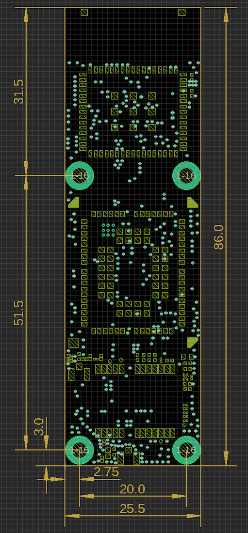
Thickness and weight to be provided at a later date.
Power consumption
To be provided at a later date.
Country compatibility
To be provided at a later date.
Ordering information
To be provided at a later date.
Certification
To be provided at a later date.
Product handling
ESD precautions
The Monitor One contains highly sensitive electronic circuitry and is an Electrostatic Sensitive Device (ESD). Handling an module without proper ESD protection may destroy or damage it permanently. Proper ESD handling and packaging procedures must be applied throughout the processing, handling and operation of any application that incorporates the module. ESD precautions should be implemented on the application board where the B series is mounted. Failure to observe these precautions can result in severe damage to the module!
Battery warning
CAUTION
RISK OF EXPLOSION IF BATTERY IS REPLACED BY AN INCORRECT TYPE. DISPOSE OF USED BATTERIES ACCORDING TO THE INSTRUCTIONS.
Disposal

This device must be treated as Waste Electrical & Electronic Equipment (WEEE) when disposed of.
Any WEEE marked waste products must not be mixed with general household waste, but kept separate for the treatment, recovery and recycling of the materials used. For proper treatment, recovery and recycling; please take all WEEE marked waste to your Local Authority Civic waste site, where it will be accepted free of charge. If all consumers dispose of Waste Electrical & Electronic Equipment correctly, they will be helping to save valuable resources and preventing any potential negative effects upon human health and the environment of any hazardous materials that the waste may contain.
Revision history
| Date | Author | Comments |
|---|---|---|
| 2022-10-24 | RK | For internal review only |
| 2022-11-17 | RK | Updated length and dimensions graphic |
| 2023-03-08 | RK | Main CPU (KM4) is M33, not M23 |