
Tracker SoM Evaluation board(001)

This is a breakout board for Particle's Tracker SoM. The Tracker SoM Cellular GNSS module is a castellated system-on-a-module that can either be reflow soldered to your own custom base board, or can be used in this evaluation board, or the carrier board.
Block diagram
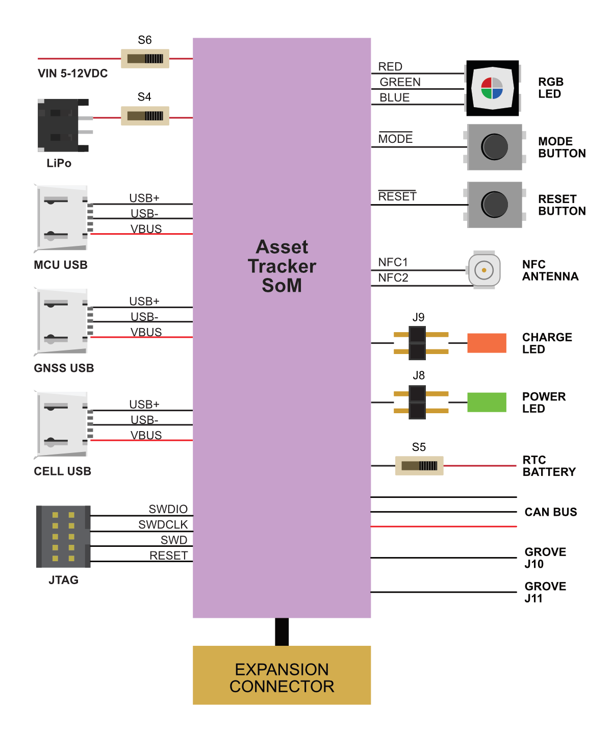
Description
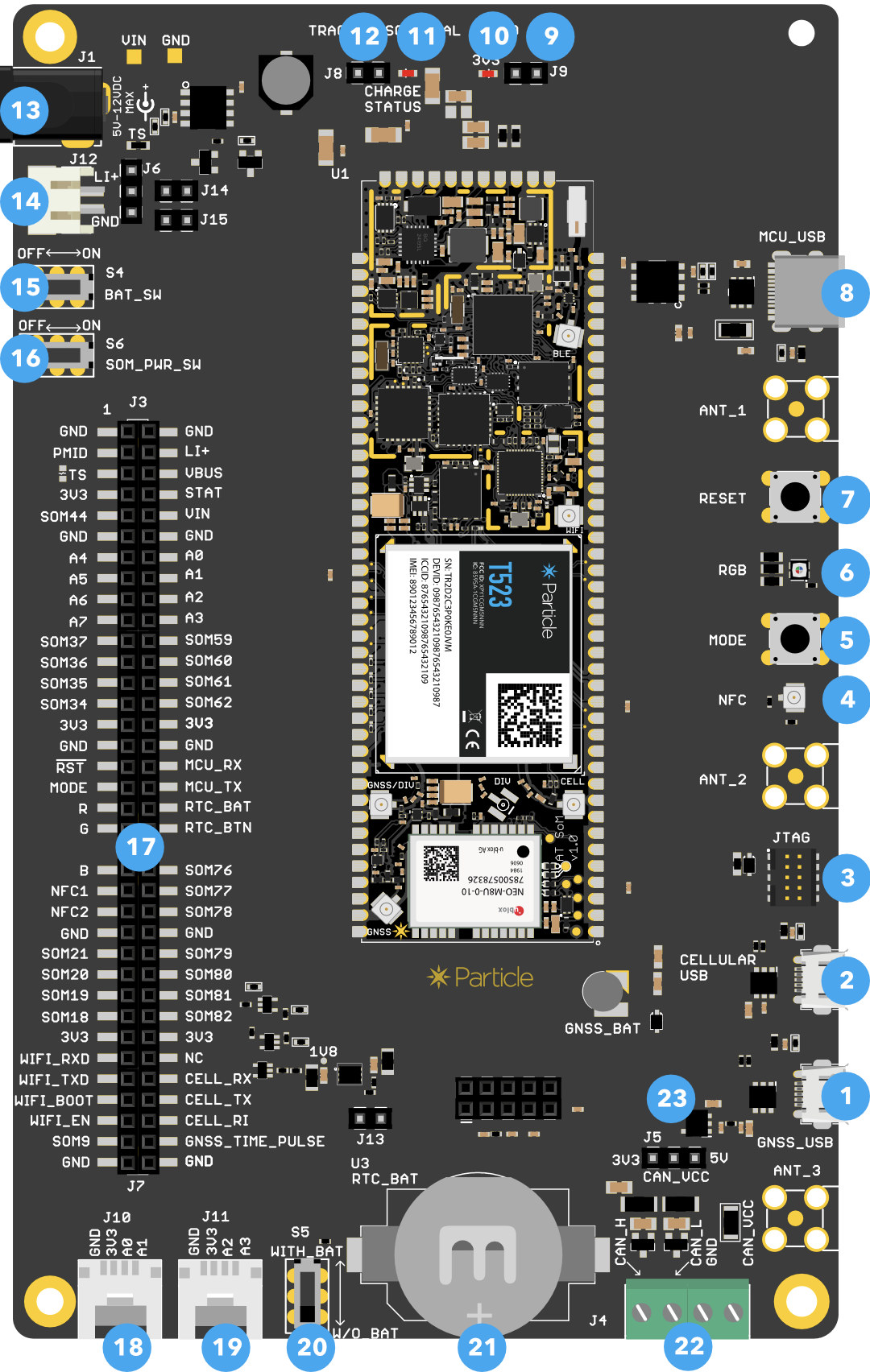
| Num | ID | Description |
|---|---|---|
| 1 | GNSS USB | u-blox GNSS USB connection |
| 2 | CELL USB | Quectel cellular modem USB connection |
| 3 | JTAG | JTAG/SWD debugging connector for nRF52 MCU |
| 4 | NFC | NFC antenna connection for NFC tag feature |
| 5 | MODE | MODE button |
| 6 | RGB | RGB status LED |
| 7 | RESET | RESET button |
| 8 | MCU USB | nRF52 MCU USB-C for debugging or power. |
| 9 | J8 | 3V3 LED jumper. Normally installed, remove to disable 3V3 LED. |
| 10 | 3V3 LED | Power LED, indicates 3.3V supply is enabled. |
| 11 | STAT LED | Charge status indicator. |
| 12 | J9 | STAT LED jumper. Normally installed, remove to disable STAT LED. |
| 13 | VIN | External power 3.9-17 VDC |
| 14 | LiPo | JST-PH connector for LiPo battery |
| 15 | S4 | Battery switch |
| 16 | S6 | SoM power switch |
| 17 | Expansion connector | |
| 18 | J10 | Grove connector (A0, A1 or I2C) |
| 19 | J11 | Grove connector (A2, A3) |
| 20 | S5 | RTC battery switch |
| 21 | RTC battery | Optional battery |
| 22 | J4 | CAN data connection and 3.3V power output |
| 23 | J5 | CAN power jumper (selects 3.3V or 5V) |
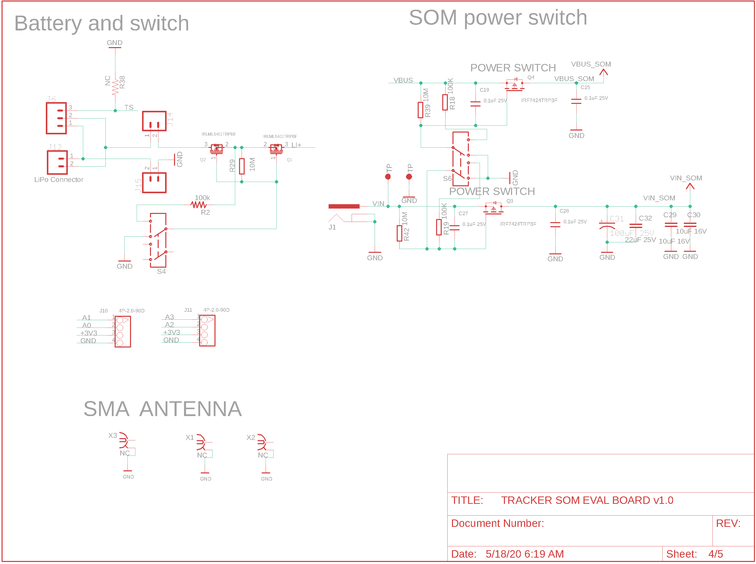
Powering the Tracker SoM evaluation board
There are several options for powering the evaluation board:
The MCU USB connector. If using a laptop with a 500 mA USB port, you should also use the LiPo battery. With a 2A tablet charger, you can power only by USB.
The VIN connector (3.9 to 17 VDC). This is useful with an external power supply. Switch S6 is the power switch.
The LiPo connector. This is typically used with a LiPo battery. Use switch S4 to enable the battery.
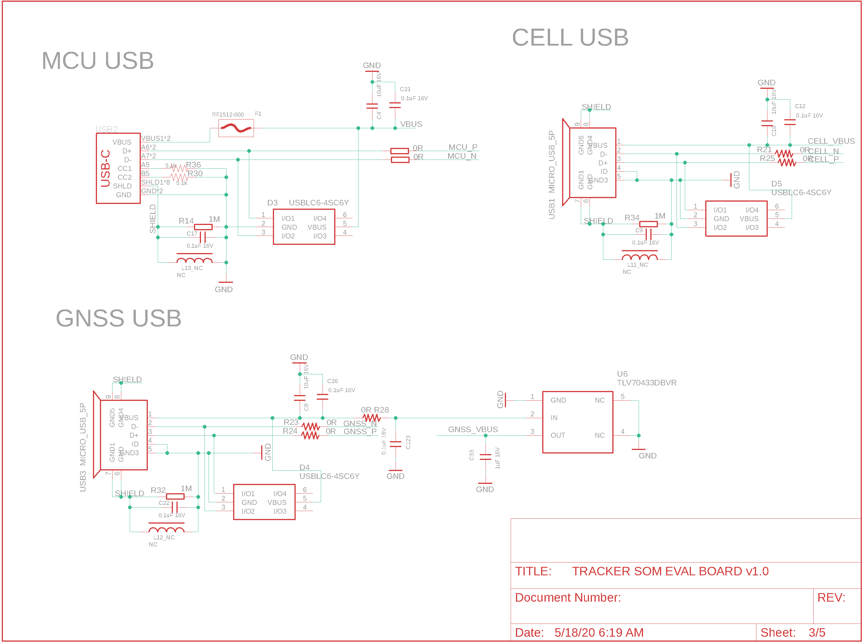
USB connectors
There are three USB connectors on the evaluation board, however you most commonly will only use the MCU USB connector.
The MCU USB connector is connected to the nRF52 MCU and can be used for Serial debugging, flashing code, and setup by USB. It can also power the AssetTracker SoM. If using a laptop with a 500 mA USB port, you should also use the LiPo battery. With a 2A tablet charger, you can power only by USB.
The GNSS USB connector is connected to the u-blox NEO-M8U GNSS. It can be used for firmware upgrades or with the u-blox u-center application.
The CELL USB connector is connected to the Quectel cellular modem. It can be used for firmware upgrades.
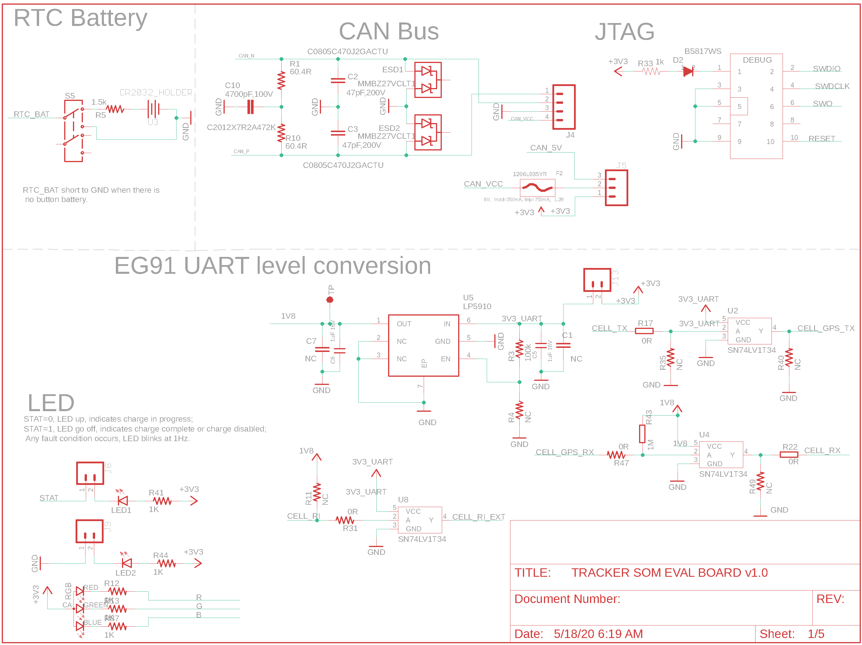
LED Indicators
The STAT LED indicates the charge status:
- Off: Not charging or no power
- On: Charging
- Blinking: Charge fault
- Flickering: No battery
Jumper J9 disconnects the charge status LED.
The 3V3 LED indicates that the 3.3V MCU power supply is enabled. Jumper J8 disconnects the power LED.
CAN connector
The four-position screw terminal connector (J4) allows connection to CAN bus devices.
| Pin | Label | Description |
|---|---|---|
| 1 | CAN_H | CAN Bus H or + |
| 2 | CAN_L | CAN Bus L or - |
| 3 | GND | Ground |
| 4 | CAN_VCC | 3.3V or 5V |
The CAN bus connection includes the 120 ohm termination resistor and ESD protection.
The CAN_VCC jumper (J5) allows the selection of the voltage on the CAN connector.
- Left position: 3.3V
- Right position: 5V
The 5V power supply is powered by a boost converter and can be turned on and off by software.
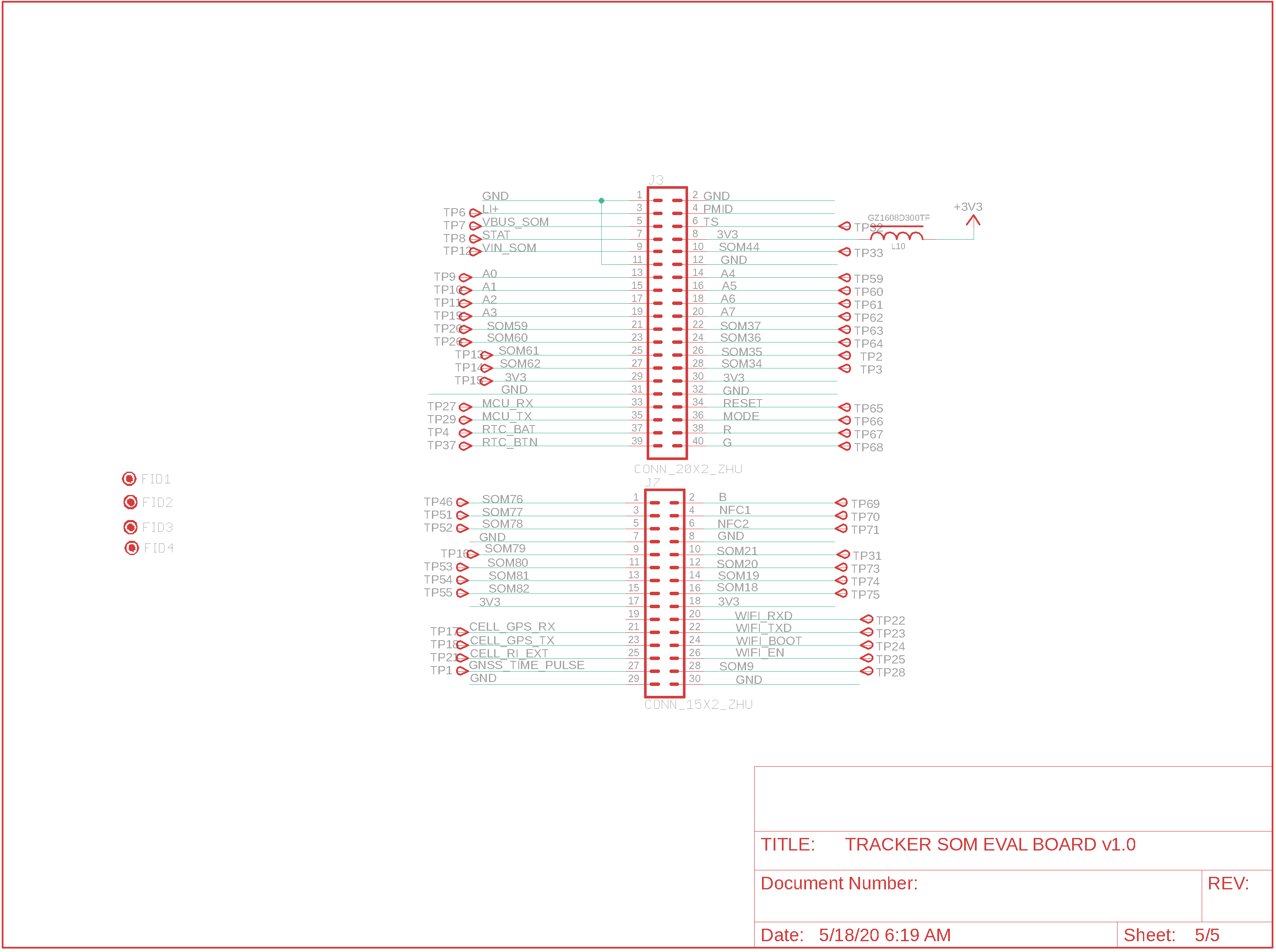
Expansion connector
| Left Description | Left | Right | Right Description | |
|---|---|---|---|---|
| Ground | GND | GND | Ground | |
| PMIC power out | PMID | LI+ | LiPo battery | |
| PMIC thermistor | TS | VBUS | nRF52 USB power | |
| 3.3V Out | 3V3 | STAT | PMIC charge status | |
| Unused | SOM44 | VIN | Power input 3.9 - 17 VDC | |
| Ground | GND | GND | Ground | |
| A4, D4, SPI MOSI | A4 | A0 | A0, D0, Wire SDA | |
| A5, D5, SPI MISO | A5 | A1 | A1, D1, Wire SCL | |
| A6, D6, SPI SCK | A6 | A2 | A2, D2, Serial1 CTS | |
| A7, D7, SS, WKP | A7 | A3 | A3, D3, Serial1 RTS | |
| Unused | SOM37 | SOM59 | Unused | |
| Unused | SOM36 | SOM60 | Unused | |
| Unused | SOM35 | SOM61 | Unused | |
| Unused | SOM34 | SOM62 | Unused | |
| 3.3V Out | 3V3 | 3V3 | 3.3V Out | |
| Ground | GND | AGND | Analog Ground | |
| RESET button | RESET | MCU_RX | Serial1 RX, GPIO D9 | |
| MODE button | MODE | MCU_TX | Serial1 TX, GPIO D8 | |
| RGB Status LED Red | R | RTC_BAT | RTC battery | |
| RGB Status LED Green | G | RTC_BTN | RTC wake button | |
| RGB Status LED Blue | B | SOM76 | Unused | |
| NFC Tag Antenna | NFC1 | SOM77 | Unused | |
| NFC Tag Antenna | NFC2 | SOM78 | Unused | |
| Unused | SOM21 | SOM79 | Unused | |
| Unused | SOM20 | SOM80 | Unused | |
| Unused | SOM19 | SOM81 | Unused | |
| Unused | SOM18 | SOM82 | Unused | |
| 3.3V Out | 3V3 | 3V3 | 3.3V Out | |
| ESP32 Serial RX | WIFI_RXD | NC | ||
| ESP32 Serial TX | WIFI_TXD | CELL_RX | Cellular serial RX | |
| ESP32 boot mode | WIFI_BOOT | CELL_TX | Cellular serial TX | |
| ESP32 enable | WIFI_EN | CELL_RI | Cellular ring indicator | |
| Unused | SOM9 | GNSS_TIME_PULSE | GNSS time pulse or fix indicator | |
| Ground | GND | GND | Ground |
Basic setup
The basic setup for the Tracker SoM Eval Board to be operational is shown below:
- Plug the cellular antenna into the U.FL connector labeled CELL on the SoM. Remember never to power up this board without the antenna being connected. There is potential to damage the transmitter of the cellular module if no antenna is connected.
- Connect power the MCU USB (8), VIN (13), or a LiPo battery (14).
- Turn on the appropriate power switches (15 and/or 16).
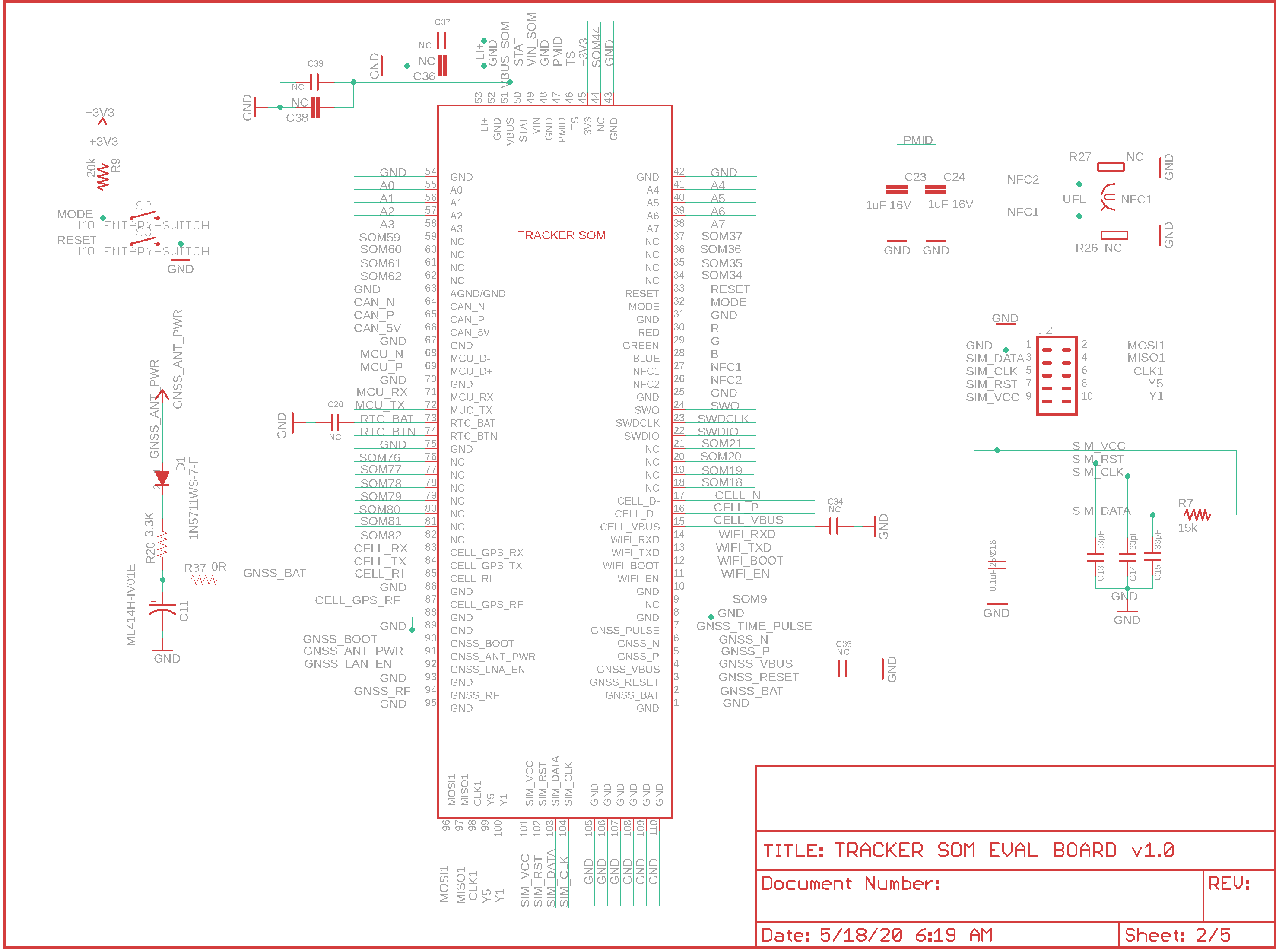
Evaluation board schematics
Tracker SoM
USB
Power switches
Expansion connector
Misc
Design files
The Tracker SoM Evaluation board is open-source and the Eagle CAD design files are available in GitHub:
https://github.com/particle-iot/tracker-hardware
Mechanical specifications
To be provided at a later date.
Dimensions and weight
| Parameter | Value | Units |
|---|---|---|
| Width | 97 | mm |
| Length | 164 | mm |
| Thickness | 14 | mm |
| Weight | g |
Weight will be provided at a later date.
Ordering information
| SKU | Description | Region | Modem | EtherSIM | Lifecycle | Replacement |
|---|---|---|---|---|---|---|
| T404MKIT | Tracker SoM LTE M1 (NorAm, EtherSIM) Evaluation Kit, [x1] | NORAM | BG96-MC | ✓ | GA | |
| T524MKIT | Tracker SoM LTE CAT1/3G/2G (Europe, EtherSIM) Evaluation Kit, [x1] | EMEAA | EG91-EX | ✓ | GA | |
| T523MKIT | Tracker SoM LTE CAT1/3G/2G (Europe) Evaluation Kit, [x1] | EMEAA | EG91-EX | NRND | T524MKIT | |
| T402MKIT | Tracker SoM LTE M1 (NorAm) Evaluation Kit, [x1] | NORAM | BG96-MC | Deprecated | T404MKIT |
†EMEAA: Selected countries in Europe, Middle East, Africa, and Asia, including Australia and New Zealand. See the cellular carrier list for more information.
Product handling
ESD precautions
The Tracker SoM contains highly sensitive electronic circuitry and is an Electrostatic Sensitive Device (ESD). Handling an module without proper ESD protection may destroy or damage it permanently. Proper ESD handling and packaging procedures must be applied throughout the processing, handling and operation of any application that incorporates the module. ESD precautions should be implemented on the application board where the B series is mounted. Failure to observe these precautions can result in severe damage to the module!
Connectors
The U.FL antenna connectors are not designed to be constantly plugged and unplugged. The antenna pin is static sensitive and you can destroy the radio with improper handling. A tiny dab of glue (epoxy, rubber cement, liquid tape or hot glue) on the connector can be used securely hold the plug in place.
Disposal

This device must be treated as Waste Electrical & Electronic Equipment (WEEE) when disposed of.
Any WEEE marked waste products must not be mixed with general household waste, but kept separate for the treatment, recovery and recycling of the materials used. For proper treatment, recovery and recycling; please take all WEEE marked waste to your Local Authority Civic waste site, where it will be accepted free of charge. If all consumers dispose of Waste Electrical & Electronic Equipment correctly, they will be helping to save valuable resources and preventing any potential negative effects upon human health and the environment of any hazardous materials that the waste may contain.
Revision history
| Revision | Date | Author | Comments |
|---|---|---|---|
| pre1 | 31 Mar 2020 | RK | Preview Release |
| pre2 | 12 May 2020 | RK | Added partial dimensions |
| 001 | 29 Jun 2020 | RK | First release |