
Shields and accessories
Shield shield
This shield is essentially an adapter that allows the user to connect Arduino compatible shields to the Spark Core. There are two functions that this shield performs: pin mapping of the Spark Core to the Arduino pin layout and voltage translation of 3.3V to/from 5V.
Operation
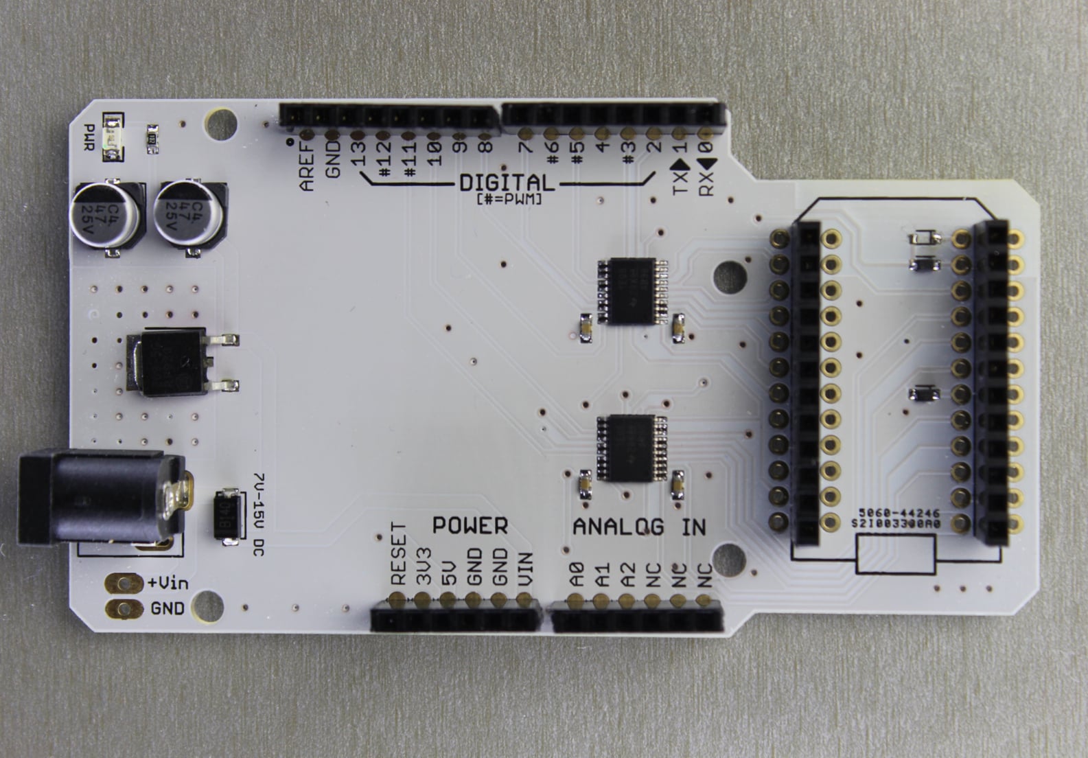
We use Texas Instruments TXB0108PWR to do the voltage translation in between Spark Core's 3.3V logic level and Arduino's 5V logic.
Due to the limited number of pin to function combinations, we have only mapped three analog channels to the Arduino footprint labeled A0, A1 and A2. Unlike other IO pins, the analog pins are rated at only a max of 3.3V and NOT 5.0V. Please remember NOT to exceed this voltage at anytime.
The shield has an onboard voltage regulator and can be powered from 7V to 15V DC. You could also power it via the USB plug on the Spark Core alone but the current would be limited to 500mA.
Specifications
- Operating voltage: 7 to 15V DC
- Current consumption: without the core plugged in 7mA at 9V DC and 150mA with the Core.
- Dimensions: 3.79" x 2.1"
- Weight: 40g
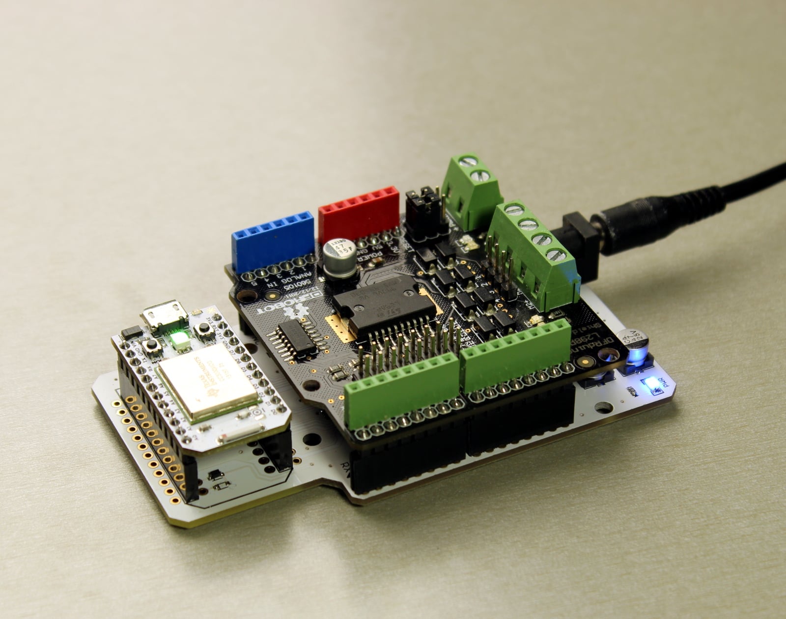
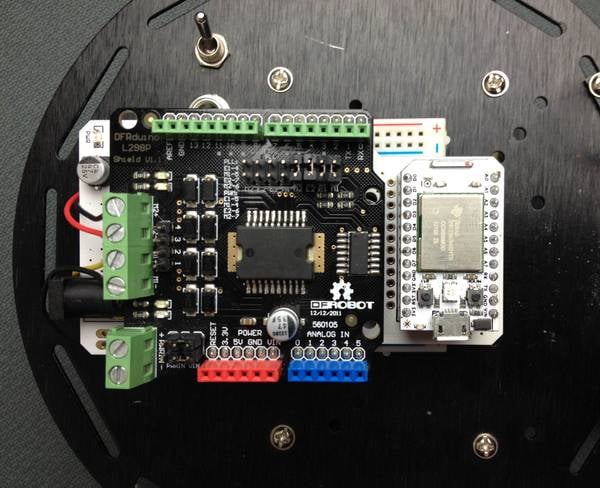
The pictures shows a robot shield interfaced with the Spark Core via the Shield Shield.
Pin mapping
Arduino | Spark Core | Peripherals
0         RX           Serial1 RX
1         TX           Serial1 TX
2         D2
3         D0           PWM
4         D3
5         D1           PWM
6         A7           PWM
7         D4
8         D5
9         D6
10        A2                 SS
11        A5           PWM,  MOSI
12        A4           PWM,  MISO
13        A3                 SCK
A0        A0           PWM*, ADC**
A1        A1           PWM*, ADC**
A2        A6           PWM*, ADC**

*  Note: These pins can also function as 3.3V
         PWM outputs or 3.3V Servo outputs.

** Note: ADC inputs are 3.3V max.
IMPORTANT: The Shield Shield does not map the Spark Core pins to like-numbered pins on the Arduino. In other words, D0 on the Spark Core is not the same as D0 on the Arduino. Please review the pin mapping table to the right and plan accordingly.
Shield Shield Hardware files >
Relay shield
The Relay Shield, in combination with the Spark Core, allows you to control high power devices over the internet. Want to control a lamp, fan or garden sprinklers? Then this is a solution for you!
IMPORTANT: This shield provides regulated power (5v) to the seated Spark Core and relays. However, it does not support power to the devices controlled by the relays.
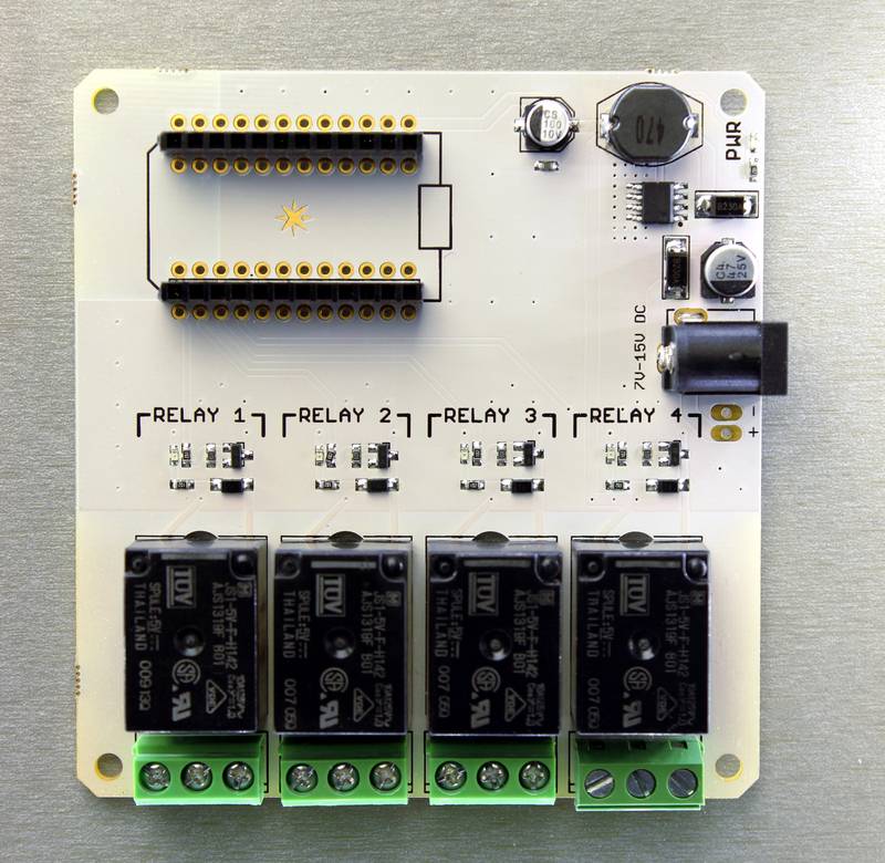
Operation
The schematic for the relay shield is simple and self explanatory. The shield has four relays that are controlled by pins D0, D1, D2 and D3 on the Core. Each relay is triggered via a NPN transistor that takes a control signal from the core and switches the relay coil ON and OFF which in turn makes or breaks the electrical contact on the output. There is also a flyback diode connected across the coil to help protect the transistor from high voltage transients caused during switching.
The relays are SPDT (Single Pole Double Throw) type, which means they have three terminals at the output: COMMON (COMM), Normally Open (NO) and Normally Closed (NC). We can either connect the load in between the COMM and NO or COMM and NC terminals. When connected in between COMM and NO, the output remains open/disconnected when the relay is turned OFF and closes/connects when the relay is turned ON. In the later case, the output remains closed/connected when the relay is OFF and opens/disconnects when the relay is ON.
Specifications
- Operating voltage: 7 to 15V DC
- Current consumption: 150mA min to 290mA (at 9V DC)
- Relay Max Voltage: 250V AC
- Relay Max Current: 10Amp at 125V AC
- Relay Part Number: JS1-5V-F (Data Sheet)
- Dimensions: 3.5 x 3.3
- Weight: 100g
Setting up the relay shield
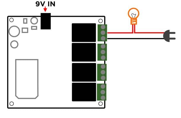
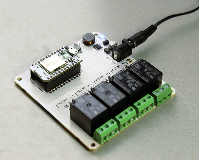
Turning ON a relay is as simple as setting the associated pin to HIGH.
The picture shows a sample setup where the relay is used as a switch to control a light bulb.
int RELAY1 = D0;
int RELAY2 = D1;
int RELAY3 = D2;
int RELAY4 = D3;

void setup()
{
   //Initilize the relay control pins as output
   pinMode(RELAY1, OUTPUT);
   pinMode(RELAY2, OUTPUT);
   pinMode(RELAY3, OUTPUT);
   pinMode(RELAY4, OUTPUT);
   // Initialize all relays to an OFF state
   digitalWrite(RELAY1, LOW);
   digitalWrite(RELAY2, LOW);
   digitalWrite(RELAY3, LOW);
   digitalWrite(RELAY4, LOW);

   //register the Particle function
   Particle.function("relay", relayControl);
}

void loop()
{
   // This loops for ever
}

// command format r1,HIGH
int relayControl(String command)
{
  int relayState = 0;
  // parse the relay number
  int relayNumber = command.charAt(1) - '0';
  // do a sanity check
  if (relayNumber < 1 || relayNumber > 4) return -1;

  // find out the state of the relay
  if (command.substring(3,7) == "HIGH") relayState = 1;
  else if (command.substring(3,6) == "LOW") relayState = 0;
  else return -1;

  // write to the appropriate relay
  digitalWrite(relayNumber-1, relayState);
  return 1;
}
An example API request to this function would look something like this:
POST /v1/devices/{DEVICE_ID}/relay

# EXAMPLE REQUEST
curl https://api.particle.io/v1/devices/0123456789abcdef/relay \
  -H "Authorization: Bearer f8a4d380cb6ffffffffffffffffffaf5e496ddf0c0" \
  -d params=r1,HIGH
Replace the access token with a valid access token, such as from particle token create.
USE EXTREME CAUTION WHEN DEALING WITH HIGH VOLTAGE !!
Programmer shield (JTAG)
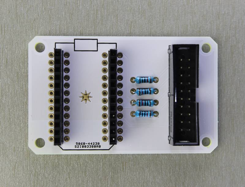
The programmer shield is a simple adapter that lets you connect a JTAG programmer to the Spark Core. If you need complete control over your Core and are comfortable with the ARM development environment, you will need this shield as an interface between the JTAG programmer and the Core.
Specifications
- Compatible JTAG programmers : STLink V2 (the only one tested)
- Dimensions: 2.2" x 1.55"
- Weight: 20g
Setting up the programmer
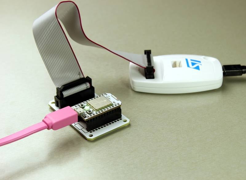
If you are using the STLink V2, you can download the supporting drivers and utilities from their website.
All of the hardware files for the JTAG shield are available for download.
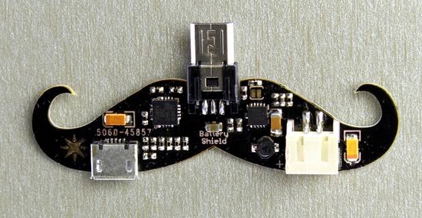
Battery shield
The battery shield is a LiPo battery charger and voltage regulator combined into one. You can use it to power your Core with any 3.7V LiPo battery and charge it at the same time via the USB port. The shield is built around Microchip's MCP73871 battery charge management controller and TI's TPS61200 boost converter for up converting 3.7V to 5.0V.
Operation
MCP73871 is an intelligent battery charge management controller that allows one to charge the battery and power the system simultaneously. There is also an under voltage lock out which protects the battery from draining completely. The TPS61200 converts the 3.7V to 4.1V battery output to a regulated 5V to power the Core or potentially any other hardware (cellphones?!) The charge current to the battery is set to 500mA.
Specifications
- Works with any 3.7V Lithium Polymer battery.
- Simultaneously charge the battery and power the core
- Dimensions: 2.3 x 0.61
- Weight: 20g
- Datasheet: MCP73871 and TPS61200
Setting up the shield
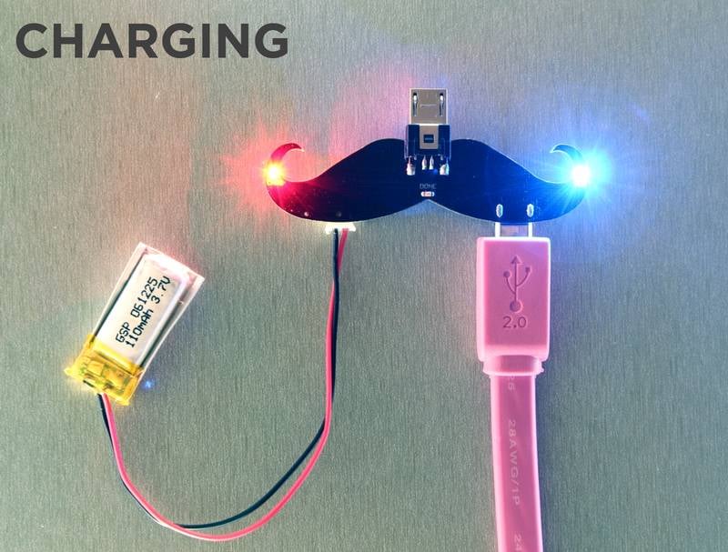
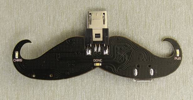
In order to just charge the battery, simply plug the battery into the JST connector (CAUTION: Remember to check the polarity of the battery header!!) and a USB cable into the microB socket as shown in the picture.
You will see the BLUE power LED light up on the shield and either the YELLOW (indicating charging in progress) or GREEN (indicating charging complete) LED light up.
To summarize the LED functions:
- Blue LED: Power indicator for the USB cable. Lights up only when the USB cable is plugged in.
- Yellow LED: Charging in progress indicator. Is ON when the battery is charging. Turns OFF when charging complete.
- Green LED: Charge Complete Indicator. This LED lights up when the battery is completely charged.
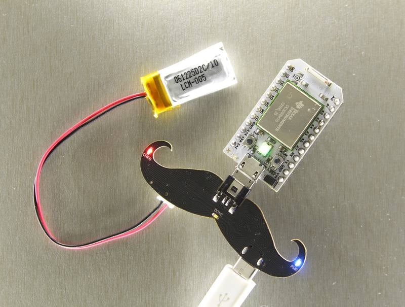
You could also power the Spark Core while the battery is charging but remember that the charging might be slower as the current will be distributed in between the Core and the battery.
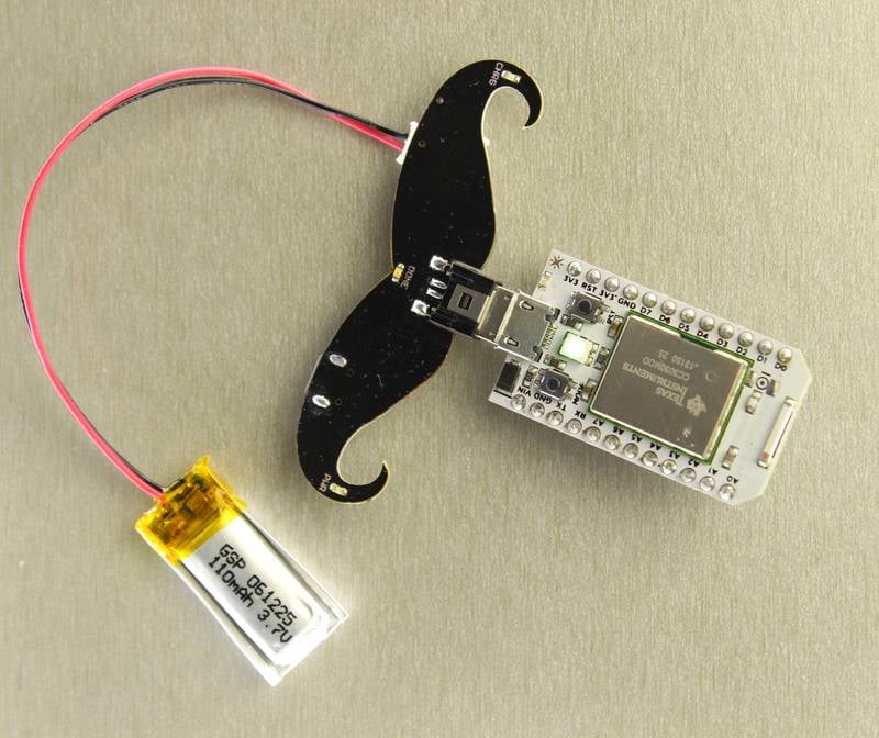
When powering the Core via the battery alone, the blue LED will NOT light up.
TIP: Remember to unplug the battery from the shield when not in use. If you leave the battery connected to the battery shield, it will eventually drain it.
CAUTION: Check the battery polarity and its voltage rating
Battery Shield Hardware Files >
Spark maker kit
1. Ceramic Capacitors (10 each)
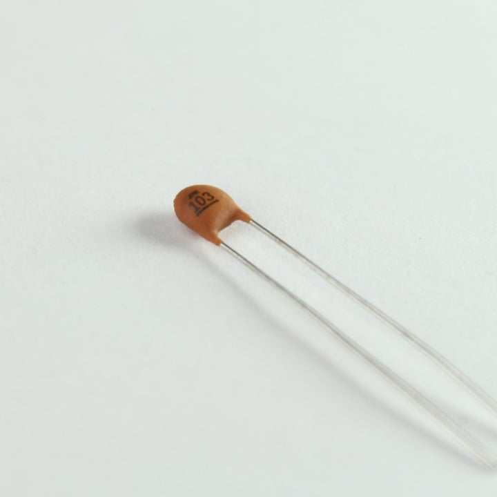
These are standard ceramic capacitors. They are widely used in analog circuits as bypass/ decoupling capacitors, in timers, filters, etc. The kit comes with:
- 10nF (0.01uF) - Number code: 103
- 100nF (0.1uF) - Number code: 104
Note: These are non-polar capacitors which means they can be oriented both ways.
2. Electrolytic Capacitor 100uF (5)
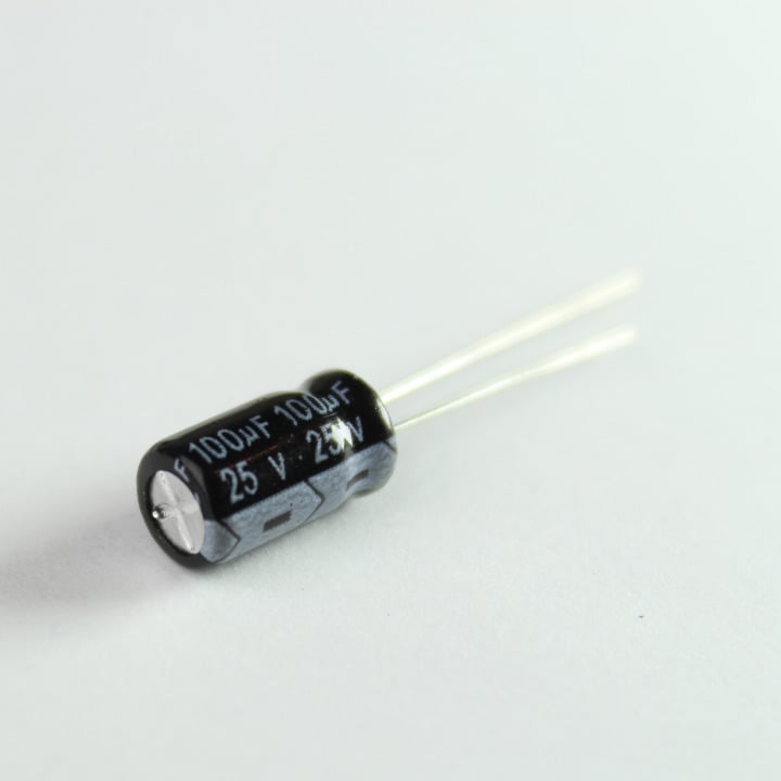
Electrolytic capacitors offer larger values and are polar. These capacitors are ideal for decoupling power supplies, as transient suppressors, and in timing circuits.
Note: These are polar capacitors. The longer lead denotes positive while the shorter one denotes negative. These are also know to "pop" when subjected to voltages higher than their ratings.
3. Headers
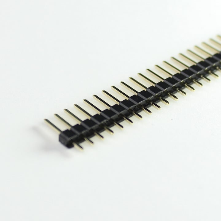
These are standard 0.1" pitch headers that can be cut to size. Very handy when building circuits on breadboard or PCBs alike.
- 8-Pin Female Headers (5)
- 40-Pin Male Breakaway Headers (2)
- 40-Pin Male Breakaway Dual-Headers (1)
4. LEDs
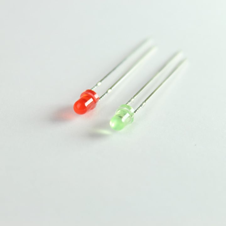
These are general purpose 3mm LEDs. You can never have enough of them! Use a resistor in series when hooking them up to the Spark Core. ( 220 ohms to 1K ohms)
- Red (5)
- Green (5)
Note: The longer lead is positive (anode) while the shorter one is negative (cathode).
5. RGB LED (1)
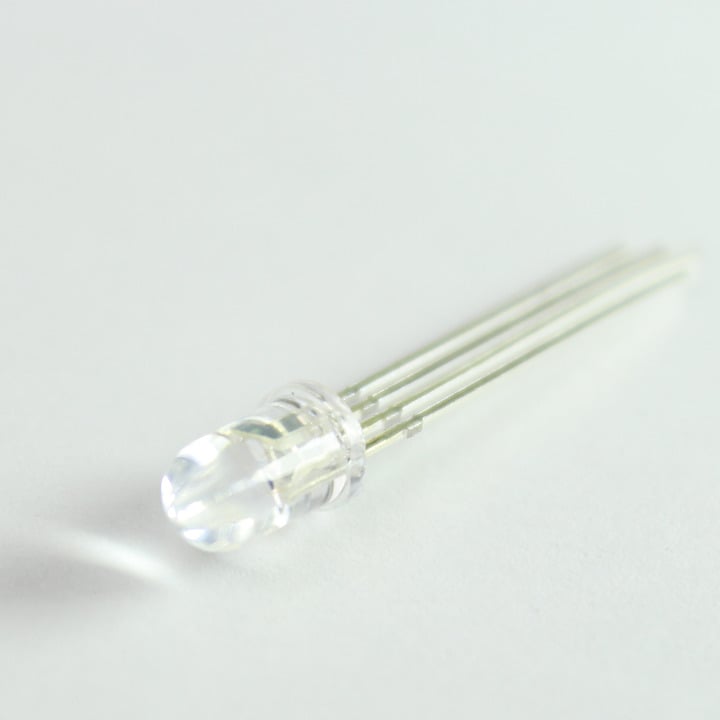
So, Red and Green aren't enough for you? Want to make bazzillion different colors? Then this RGB LED will do it for ya. You can mix colors by connecting each pin to an analogWrite compatible pin on the Core and feed them different values. Let the disco party begin!
This LED has four pins, one for each color and a common anode (+) pin.
6. NPN Transistor (1)
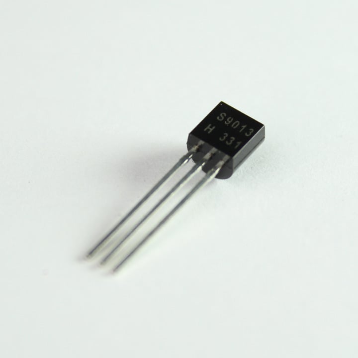
S9013 is a general purpose small signal NPN transistor rated at 40V, 500mA.
You can use this transistor to switch small loads like relays, mini motors, buzzers, etc.
7. Diode (6)
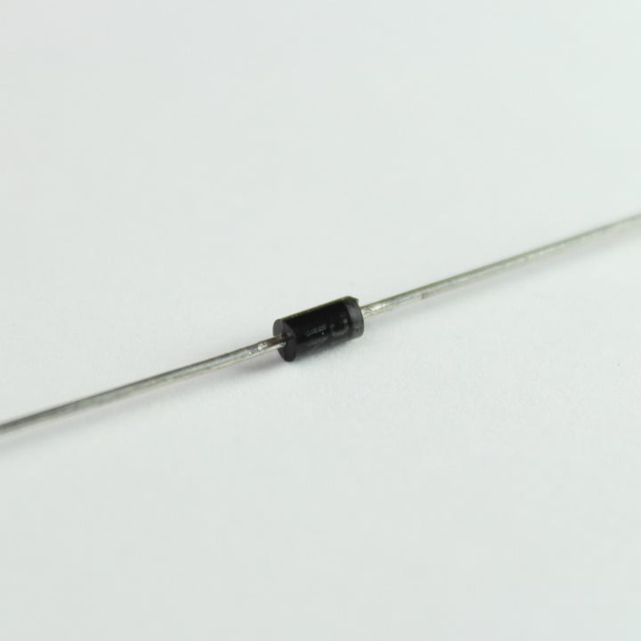
1N4004 is a general purpose diode rated at 400V, 1000mA with a forward voltage drop of 1.1V. Excellent as a fly-back diode or as a general rectifying diode.
8. Micro Servo (1)
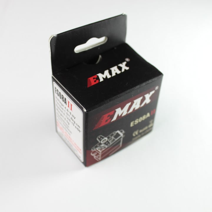
Emax ES08A is a mini RC servo motor.
- Operating Voltage: 4.8 to 6.0VDC
- Stall Torque: 1.8Kg/cm
- Speed: 0.10sec/degree at no load
Wiring:
- Yellow - Signal (D0, D1, A0, A1, A4, A5, A6, A7)
- Orange - +5V (VIN)
- Brown - Ground (GND)
Note: The Ground pin may vary as Brown or Black, +5V pin may vary as Orange or Red and Signal pin may vary as Yellow or White and sometimes Orange if there is already a Red and Black wire.
9. Deluxe Jumper Wire Pack (1)
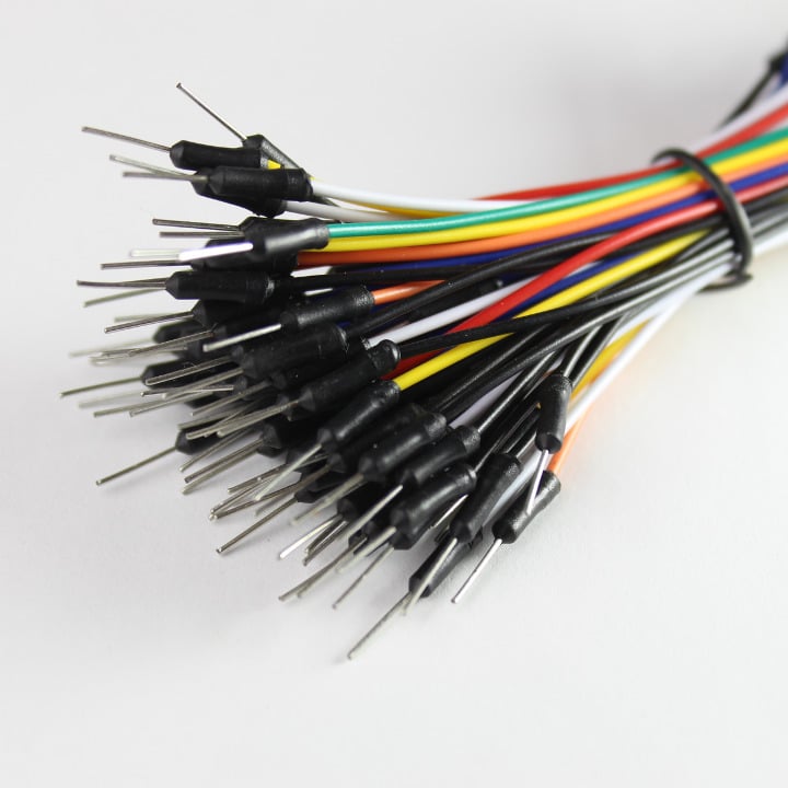
Multi-colored and stripped. You can never have enough of these either.
10. USB Micro B Cable (1)
A custom Spark USB cable for you Core! We were really excited to have our logo printed on them.
11. Mini DC Motor (1)
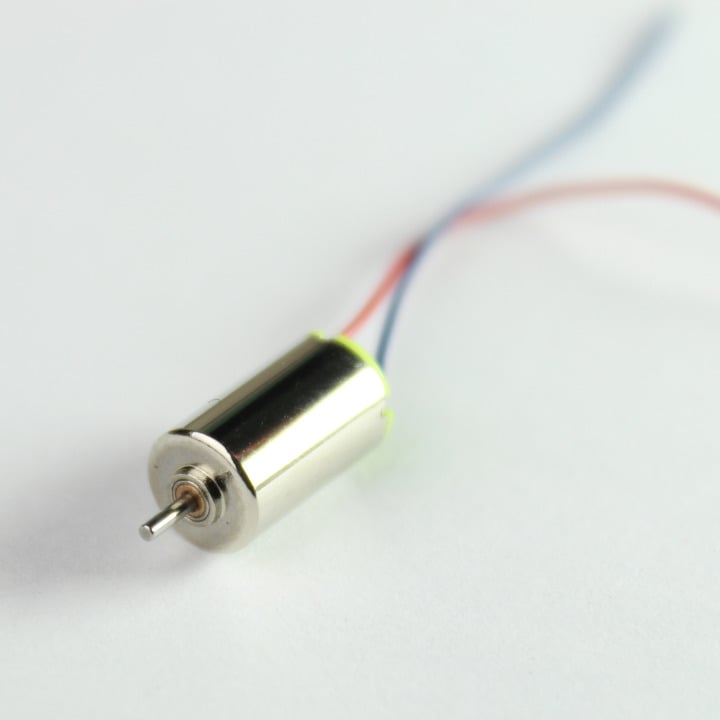
This is a simple DC motor that you can switch using the NPN transistor provided in the kit.
12. Vibration Motor (1)
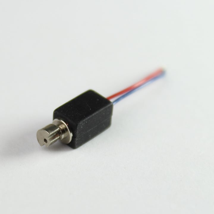
Wanna give your next Spark Core project a tactile feedback? This vibration motor serves the purpose nicely. Use the NPN transistor to switch it.
13. Piezo Buzzer (1)
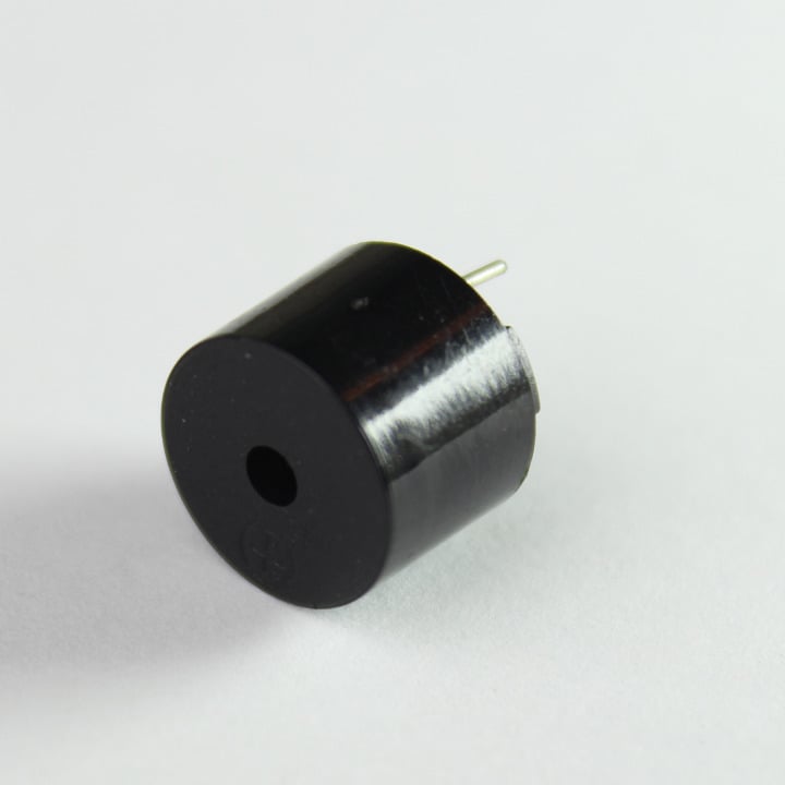
Add an audible feedback to your project with this buzzer. The longer lead is positive and the shorter is negative. You will need a transistor to drive it.
Note: The sound gets annoying after a while. Use it sparingly!
- Operating Voltage: 4.0 to 7.0 V DC
- Oscillation Frequency: 2.3KHz
- Current: 30mA
- Sound Pressure: 85dB
14. Mini Pushbuttons (3)
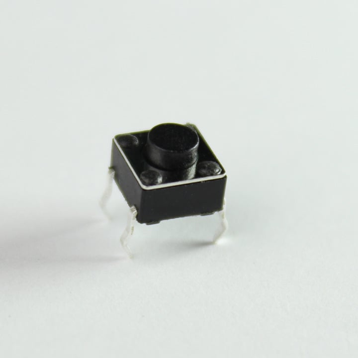
These are nifty little switches that plug nicely into a breadboard or a proto-board. They are normally-open type and are rated at 12V, 50mA.
15. DPDT Switch (2)
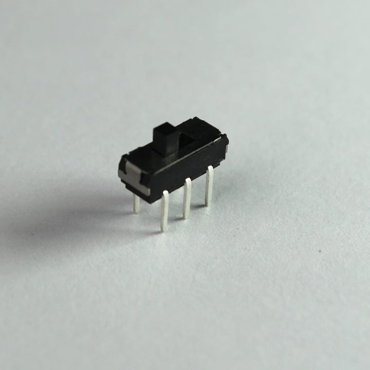
This is a tiny Double Pole Double Throw (DPDT) Switch with 6 legs.
16. Shift Register IC (1)
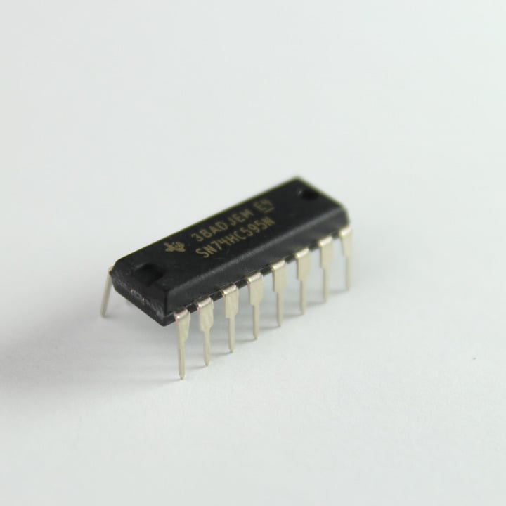
74HC595 is an 8 bit serial-in parallel-out shift register commonly used as an output expander. You can drive of up to 8 outputs from only 3 lines (using one chip). You could potentially daisy chain multiple of these to get even more outputs.
17. Tilt Sensor (2)
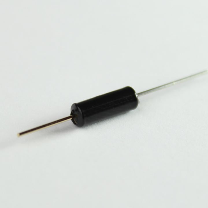
SW-200D is a tiny tilt sensor that when tilted to more than 30 degrees will internally connects its two terminals together. The magic happens with the use of gravity and a tiny metal ball.
You can use to it detect tilt, orientation or vibrations.
18. Temperature Sensor (1)
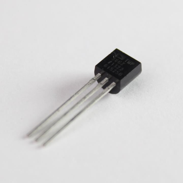
The TMP36 is a low voltage, precision centigrade temperature sensor. It provides a voltage output that is linearly proportional to the Celsius (centigrade) temperature. The TMP36 does not require any external calibration to provide typical accuracies of ±1°C at +25°C and ±2°C over the −40°C to +125°C temperature range.
19. Thermistor (2)
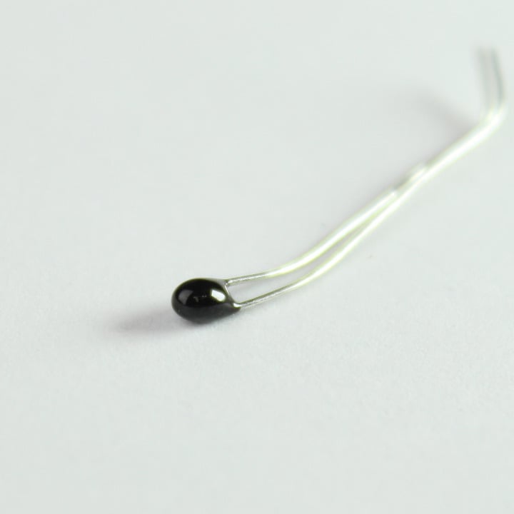
A thermistor is a temperature dependent resistor. This one is a NTC type (Negative Temperature Coefficient), which means its resistance decreases with an increase in temperature.
Unlike the TMP36, you will need to use this as a part of a voltage divider circuit as nicely described in this tutorial.
20. Force-Sensitive Resistor (1)
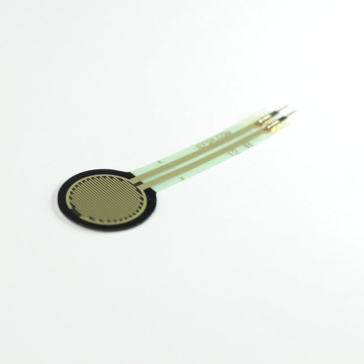
Manufacturer Part Number: Interlink 30-81794 This is a force sensitive resistor with a 0.5" diameter and an operating force from 10g to 1000g. Their resistance decreases with an increase in applied pressure.
21. Photo Resistors (2)
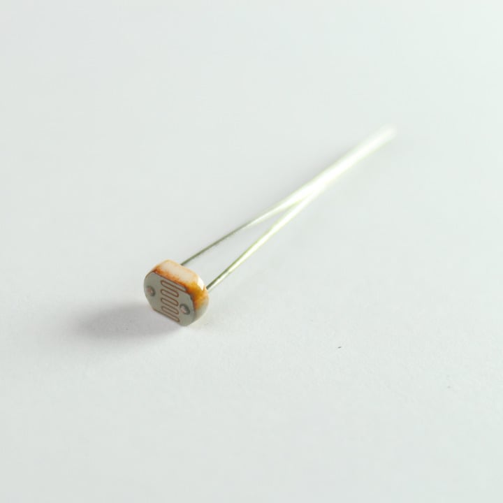
A photo resistor is a light dependent resistor whose resistance decreases with the increase in the intensity of light striking it. You can use it to detect the ambient light in the surrounding, detect shadows or use it as a part of a burglar alarm system.
22. Resistors
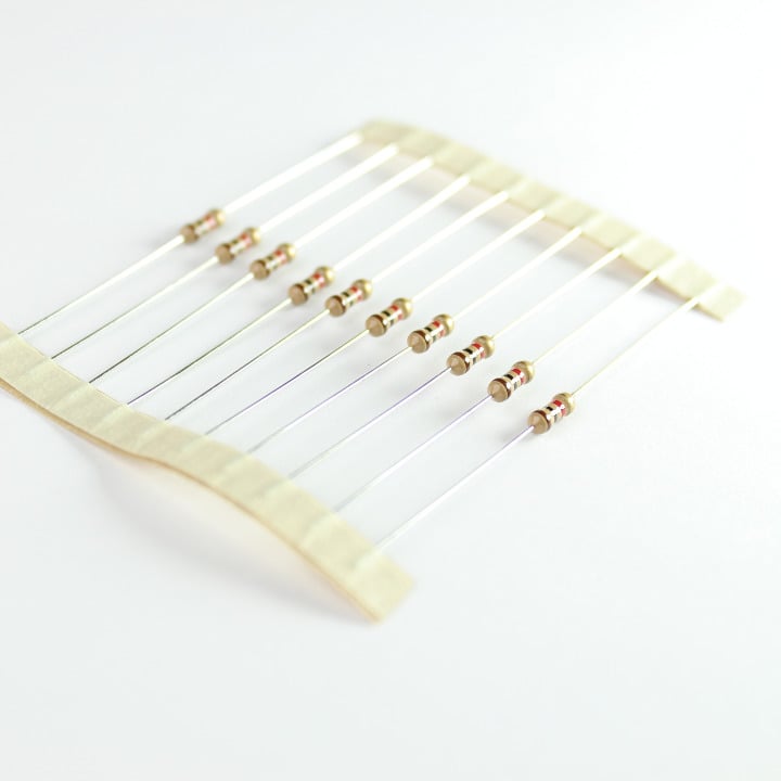
There are three different value resistor in this kit. All of them are rated at 5%, 1/4 Watt.
- 330-Ohm (10)
- 1K-Ohm (10)
- 10K-Ohm (10)
You can use this online guide to help identify which resistor is which value.
23. Rotary Potentiometer (1)
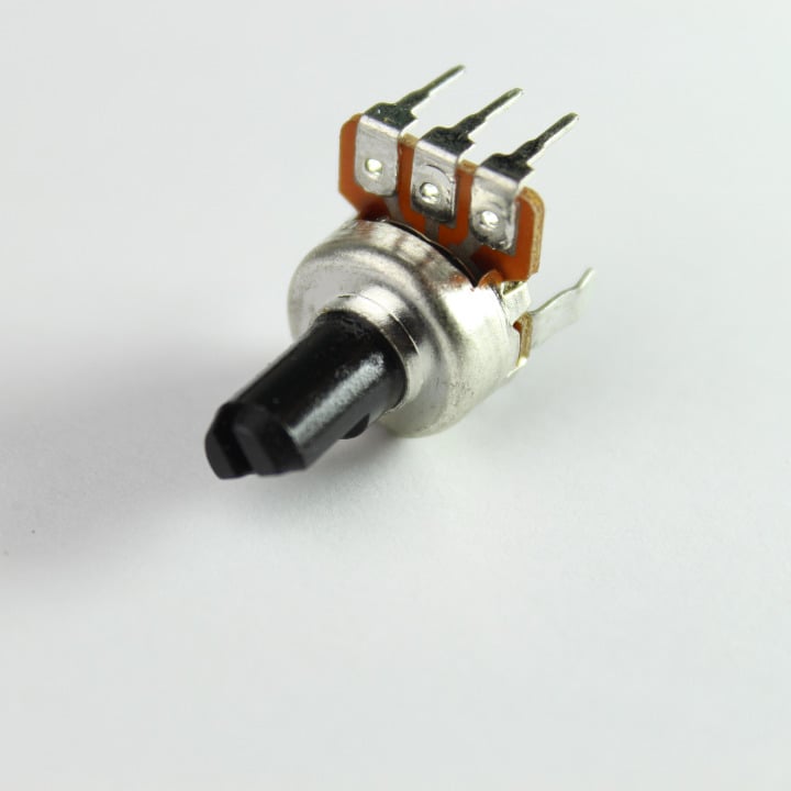
This is a variable resistor whose value can be changed by simply turning the knob.
24. Proto-board (1)
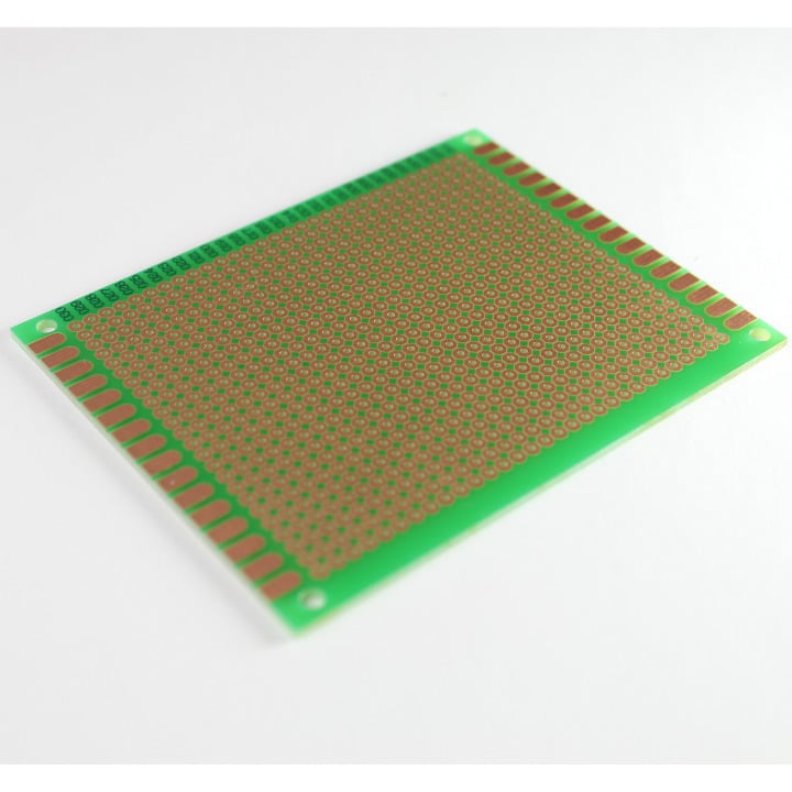
This is a 7" x 9" general purpose dot-matrix prototyping PCB.
25. Spark Core - u.FL or CA (1)
Your very own Spark Core, ready to take over the world, one byte at a time.
Spark RC car kit
The RC car kit is a two-wheeled differentially driven platform that you can control using a Spark Core.
Kit contents
NOTE: This is no longer available for purchase.
- Pin 4: Connects with M1
- Pin 5: Connects with E1 (PWM)
- Pin 6: Connects with E2 (PWM)
- Pin 7: Connects with M2
Where E1 and E2 control the speed of the motors, while M1 and M2 change the direction.
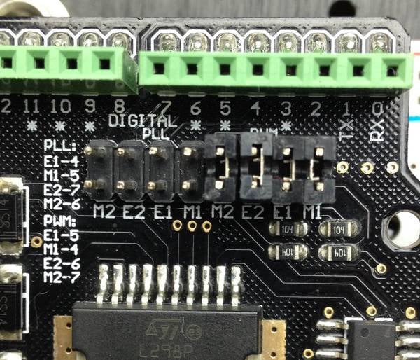
Connect the left and right motor terminals to M2+,M2-,M1+ and M1- respectively.
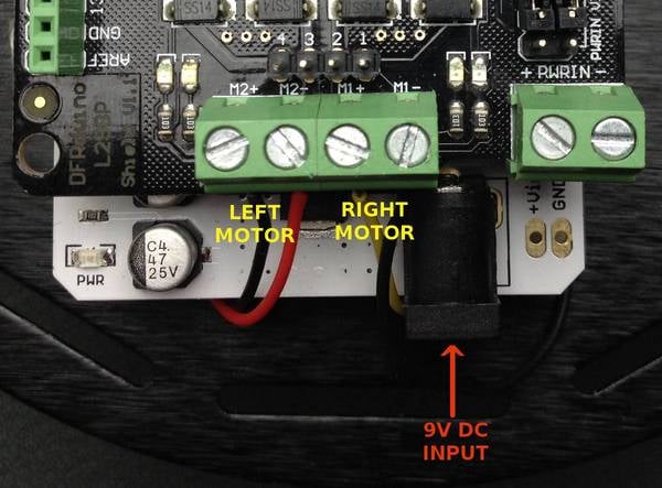
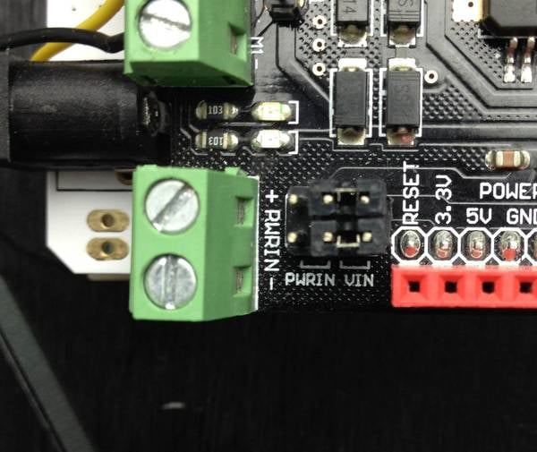
The motors can run from a voltage in the range of 5V to 9V DC. The jumpers can be set to get power from Vin from the Shield below.
Example code
A simple example for controlling the RC Car is as described:
int leftMotorEnable   = D1;
int rightMotorEnable  = A7;
int leftMotorDir    = D3;
int rightMotorDir   = D4;

void setup()
{
  //Register Particle function
  Particle.function("rccar", rcCarControl);

  pinMode(leftMotorDir, OUTPUT);
  pinMode(leftMotorEnable, OUTPUT);
  pinMode(rightMotorDir, OUTPUT);
  pinMode(rightMotorEnable, OUTPUT);

  pinMode(D7,OUTPUT);
}

void loop()
{
  // Nothing to do here
}

/*******************************************************************************
 * Function Name  : rcCarControl
 * Description    : Parses the incoming API commands and sets the motor control
          pins accordingly
 * Input          : RC Car commands
          e.g.: rc,FORWARD
            rc,BACK
 * Output         : Motor signals
 * Return         : 1 on success and -1 on fail
 *******************************************************************************/
int rcCarControl(String command)
{
  if(command.substring(3,7) == "STOP")
  {
    digitalWrite(leftMotorEnable,LOW);
    digitalWrite(rightMotorEnable,LOW);

    digitalWrite(leftMotorDir,LOW);
    digitalWrite(rightMotorDir,LOW);

    return 1;
  }

  if(command.substring(3,7) == "BACK")
  {
    digitalWrite(leftMotorDir,LOW);
    digitalWrite(rightMotorDir,HIGH);

    digitalWrite(leftMotorEnable,HIGH);
    digitalWrite(rightMotorEnable,HIGH);

    return 1;
  }

  if(command.substring(3,10) == "FORWARD")
  {
    digitalWrite(leftMotorDir,HIGH);
    digitalWrite(rightMotorDir,LOW);

    digitalWrite(leftMotorEnable,HIGH);
    digitalWrite(rightMotorEnable,HIGH);

    return 1;
  }

  if(command.substring(3,8) == "RIGHT")
  {
    digitalWrite(leftMotorDir,HIGH);
    digitalWrite(rightMotorDir,HIGH);

    digitalWrite(leftMotorEnable,HIGH);
    digitalWrite(rightMotorEnable,HIGH);

    return 1;
  }

  if(command.substring(3,7) == "LEFT")
  {
    digitalWrite(leftMotorDir,LOW);
    digitalWrite(rightMotorDir,LOW);

    digitalWrite(leftMotorEnable,HIGH);
    digitalWrite(rightMotorEnable,HIGH);

    return 1;
  }

  // If none of the commands were executed, return false
  return -1;
}
To send API commands:
# Sending command to go forward
curl https://api.particle.io/v1/devices/0123456789abcdef/rccar -H "Authorization: Bearer f8a4d380cb6ffffffffffffffffffaf5e496ddf0c0" -d params=rc,FORWARD
Replace the access token with a valid access token, such as from particle token create.
Motor driver shield specifications
The motor driver shield is based around the L298 Full-bridge motor driver chip.
- Logic voltage: 5V DC
- Logic Supply Current: 36mA
- Motor drive voltage: 7V to 12V DC
- Motor drive current: 2Amp Max