
Tracker eval board tutorials
This section has information on prototyping with the Tracker Evaluation board experiment and add new features, with an eye toward being able to easily migrate to the Tracker One, Tracker Carrier Board, or Tracker SoM for production.
DHT11 temperature and humidity example
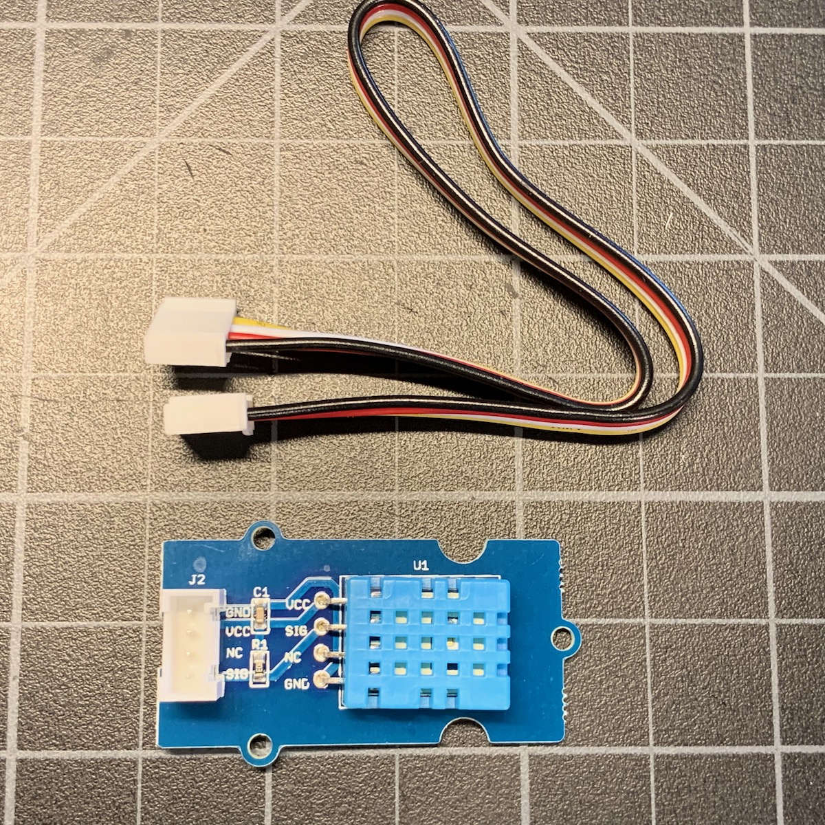
The Tracker SoM Evaluation Board comes with a Grove DHT11 temperature and humidity sensor and a short 4-pin cable.
Connect the sensor
Connect the sensor to the 4-pin ribbon cable and the other end to the evaluation board. Either port can be used but this example assumes J10, the outer connector, pin A0 and A1.
Getting the Tracker Edge firmware
You can download a complete project for use with Particle Workbench as a zip file here:
Version:
- Extract tracker-temperature.zip in your Downloads directory
- Open the tracker-temperature folder in Workbench using File - Open...; it is a pre-configured project directory.
- From the Command Palette (Command-Shift-P or Ctrl-Shift-P), use Particle: Configure Project for Device.
- If you are building in the cloud, you can use Particle: Cloud Flash or Particle: Cloud Compile.
- If you are building locally, open a CLI window using Particle: Launch CLI then:
particle library copy
Manually
The Tracker Edge firmware can be downloaded from GitHub:
https://github.com/particle-iot/tracker-edge
You will probably want to use the command line as there are additional commands you need to run after cloning the source:
git clone git@github.com:particle-iot/tracker-edge.git
cd tracker-edge
git submodule update --init --recursive
- Open Particle Workbench.
- From the command palette, Particle: Import Project.
- Run Particle: Configure Workspace for Device, select version 1.5.4-rc.1, 2.0.0-rc.3, or later, Tracker, and your device.
- Run Particle: Compile and Flash.
Add the libraries
From the command palette in Workbench, Particle: Install Library then enter Grove_Temperature_And_Humidity_Sensor. Repeat for TemperatureHumidityValidatorRK.
If you prefer to edit project.properties directly, add these:
The first library is the interface for the temperature sensor.
Because the sensor has a tendency to return incorrect values but does not include a checksum or CRC to determine that this has happened, the second library filters the results by collecting the last 10 samples, selecting only the samples within 1 standard deviation of the mean, and taking the mean of these samples without the outliers.
The full source
The details
#include "Grove_Temperature_And_Humidity_Sensor.h"
#include "TemperatureHumidityValidatorRK.h"
These are the header files for the two libraries we use. Note that you must Particle: Install Library first; you can't only include the header file.
DHT tempSensor(A1);
TemperatureHumidityValidator validator;
These are the global variables for the two features we use. Note the use of A1. If you connected the sensor to the other Grove connector you'd use A3 instead.
// Sample the temperature sensor every 2 seconds. This is done so the outlier values can be filtered out easily.
const unsigned long CHECK_PERIOD_MS = 2000;
Because we filter the temperature sensor results to remove the outliers, we sample the sensor every 2 seconds. That way, when a location event is generated, we don't have to wait for enough samples to return a value.
void setup()
{
    Tracker::instance().init();

    // Callback to add key press information to the location publish
    Tracker::instance().location.regLocGenCallback(myLocationGenerationCallback);

    // Initialize temperature sensor
    tempSensor.begin();

    Particle.connect();
}
In setup() we must do several things:
- Initialize the Tracker Edge firmware
- Register a location generation callback
- Initialize the temperature sensor
- Connect to the Particle cloud
void loop()
{
    Tracker::instance().loop();


    if (millis() - lastCheck >= CHECK_PERIOD_MS) {
        lastCheck = millis();

        validator.addSample(tempSensor.getTempCelcius(), tempSensor.getHumidity());
    }
}
In loop() we:
- Call the Tracker Edge loop function
- Periodically sample the temperature and humidity sensor and pass the values to the validator.
void myLocationGenerationCallback(JSONWriter &writer, LocationPoint &point, const void *context)
{
    float tempC = validator.getTemperatureC();
    if (!isnan(tempC)) {
        writer.name("temp").value(tempC, 2);
    }

    float hum = validator.getHumidity();
    if (!isnan(hum)) {
        writer.name("hum").value(hum, 1);
    }

}
Finally, in the location generation callback, we add the temperature and humidity values if valid.
Results
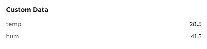
If you open the event viewer, you can see the location events now have temp and hum keys!
{
    "cmd":"loc",
    "time":1595867181,
    "loc":{
        "lck":1,
        "time":1595867182,
        "lat":42.469732,
        "lon":-75.064801,
        "alt":348.621,
        "hd":215.61,
        "h_acc":9,
        "v_acc":15,
        "cell":42.3,
        "batt":96.5,
        "temp":29,
        "hum":42
    },
    "trig":[
        0:"lock"
    ],
    "req_id":2
}
If you open the map view and then the device, the new fields will appear in the Custom Data section.
I2C sensor example
One of the best ways to expand the Tracker One is using I2C, since that interface makes it possible to add multiple external peripherals off the single M8 connector. You can use the same techniques on the Tracker SoM Evaluation Board and Tracker SoM.
For this example we'll add temperature, pressure, and humidity information to location publishes using the Tracker SoM Evaluation Board.
We'll also use the SparkFun Qwiic line of products for easy prototyping. For production you'd probably make your own custom board with the sensor on it, instead.
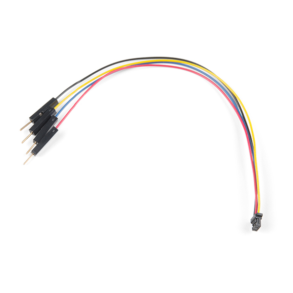
With the Evaluation board you'll need the Qwiic connector to prototyping wires or the cable assortment that includes it.
And you'll need a sensor, in this case a SparkFun Atmospheric Sensor Breakout - BME280 (Qwiic).
- Connect the following wires to the Tracker SoM Evaluation Board expansion connector:
| Color | Pin | Purpose |
|---|---|---|
| Blue | MCU_RX | SDA (I2C data) |
| Yellow | MCU_TX | SCL (I2C clock) |
| Red | 3V3 | Power 3.3V |
| Black | GND | Ground |
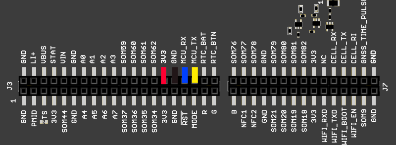
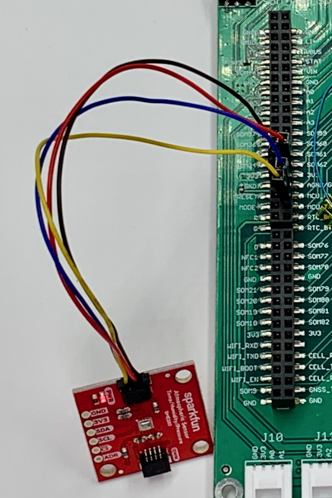
Instead of using D0/D1 for I2C like on other Particle devices, in this case we'll be using the multi-function port pins MCU_RX and MCU_TX instead. On the Tracker SoM the TX and RX pins can be reconfigured to be Wire3 instead of Serial1, allowing a single set of pins to be GPIO, serial, or I2C on the M8 connector.
Note: All GPIO, ADC, and peripherals such as I2C, Serial, and SPI are 3.3V maximum and are not 5V tolerant. You must never use pull-ups to 5V on the I2C interface!
You can download a complete project for use with Particle Workbench as a zip file here:
Version:
- Extract tracker-bme280.zip in your Downloads directory
- Open the tracker-bme280 folder in Workbench using File - Open...; it is a pre-configured project directory.
- From the Command Palette (Command-Shift-P or Ctrl-Shift-P), use Particle: Configure Project for Device.
- If you are building in the cloud, you can use Particle: Cloud Flash or Particle: Cloud Compile.
- If you are building locally, open a CLI window using Particle: Launch CLI then:
particle library copy
Manually
- Start with the base Tracker Edge firmware
- Add and copy the Adafruit_BME280_RK library into the project:
$ particle library add Adafruit_BME280_RK
$ particle library copy Adafruit_BME280_RK
- Here's the source:
Most of it is boilerplate, but looking in more closely:
- Include the library header for the sensor and add any global variables it requires:
#include "Adafruit_BME280.h"
Adafruit_BME280 bme(Wire3);
bool hasSensor = false;
- Disable
Serial1and enableWire3on the multi-function pins.
Serial1.end();
Wire3.begin();
- Initialize the sensor, in this case a BME280 on Wire3 using address 0x77.
hasSensor = bme.begin(0x77);
Log.info("hasSensor=%d", hasSensor);
- In our location callback, add the temperature, pressure, and humidity data.
void myLocationGenerationCallback(JSONWriter &writer,
    LocationPoint &point, const void *context)
{
    if (hasSensor) {
        writer.name("temp").value(bme.readTemperature(), 2); // degrees C
        writer.name("pres").value(bme.readPressure() / 100.0, 2); // hPA
        writer.name("hum").value(bme.readHumidity(), 2); // Relative humidity %
    }
    else {
        Log.info("no sensor");
    }
}
- Now you can see the extra data in the
locevent!
{
    "cmd":"loc",
    "time":1593091308,
    "loc":
    {
        "lck":1,
        "time":1593091309,
        "lat":42.469732,
        "lon":-75.064801,
        "alt":324.11,
        "hd":222.95,
        "h_acc":6.8,
        "v_acc":9.2,
        "cell":42.3,
        "batt":72.2,
        "cell":37.1,
        "batt":98.8,
        "temp":24.92,
        "pres":973.39,
        "hum":42.46
    },
    "trig":
    [
        "time"
    ],
    "req_id":2
}
M8 evaluation board adapter
If you are interested in prototyping designs intended to connect to the Tracker One M8 connector, but want to do it using the Tracker SoM Evaluation Board, you may be interested in this project. It's only a set of design files, BoM, etc. and you'd need to fabricate the board and build it yourself; it's not available as a finished product. It also explains a bit more about how the M8 connector can be used.
Design files
The Tracker SoM Evaluation board is open-source and the Eagle CAD design files are available in the Tracker Hardware GitHub repository.