
About Modbus
The basics
Background
Modbus is an open-sourced client-server protocol developed in 1979. Modbus is a common communication standard used in industrial automation, where it is used to enable communication between PLCs, motor controllers, sensors, upstream SCADA systems, and more.
Modbus is a multi-drop communication bus, meaning there can be multiple devices connected to a single network. The device requesting the data is called the Modbus Client (master) and the device receiving and/or returning data is the Modbus Server (slave). Each Server device connected via Modbus will have its own unique Server Address. In a typical Modbus network, there is one Client and up to 247 Servers that can be connected. In the example application highlighted in this page, the Particle device is the Client and will be controlling the Modbus network.
Modbus has many benefits, but the main benefit is reliable communication that can be transmitted over large distances by using RS-485. RS-485 is a differential communication standard that provides far superior noise immunity when compared to RS-232. This allows for much longer transmission lines which is key for industrial applications like motor control, system monitoring, power meters, and sensors like temperature, humidity, and pressure.
The Modbus standard can be used over a number of different electrical busses, including RS-232, RS-485, and Ethernet. This example will focus on an RS-485 bus.
Benefits
Modbus is very common in the industrial space as it provides an easy entry point into existing systems for retrofit. Modbus abstracts away machine communication which enables the user to access many types of data over one network. This creates a centralized way to request data from many types of devices.
Types
There are many types of Modbus protocol and each type is a derivative of the next and each protocol was created for different applications. Modbus RTU is by far the most common and the example application and the rest of this document uses this type of Modbus. Below is a list of the types of Modbus.
- Modbus RTU
- Modbus ASCII
- Modbus TCP/IP
- Modbus over TCP/IP
- Modbus over UDP
- Modbus Plus
- Pemex Modbus
- Enron Modbus
Modbus RTU message structure
Modbus RTU uses a simple message structure that is easy to deploy. It communicates using raw words, bytes, and bits. The message structure is similar for each transaction. Below is a table highlighting the message structure
| Name | Function |
|---|---|
| Start | Marks beginning of transaction |
| Server Address | Unique value for each addressable server on the network |
| Function Code | Indicates the operation being performed |
| Data | Any number of bytes and is dictated by the operation being performed |
| CRC | Cyclic Redundancy Check |
| End | Marks end of transaction |
The protocol has different types of registers which are reserved for the various operations that need to be performed. When a function refers to an "input" this is a read-only function whereas a "register" can also be written in addition to being read. Below is a table of the various registers or function codes.
Coils were originally for relays and solenoids, but could be other types of write-only outputs now.
| Function Code (HEX) | Description |
|---|---|
| 1 (0x01) | Read Coil Status |
| 2 (0x02) | Read Discrete Inputs |
| 3 (0x03) | Read Holding Registers |
| 4 (0x04) | Read Input Registers |
| 5 (0x05) | Write Single Coil |
| 6 (0x06) | Write Single Register |
| 15 (0x0F) | Write Multiple Coils |
| 16 (0x10) | Write Multiple Registers |
| 22 (0x16) | Mask Write Register |
| 23 (0x17) | Read Write Multiple Registers |
Example hardware
The goal of this application is to implement a Modbus RTU network using the Particle Platform as the Modbus client along with publishing the data from the modbus to the cloud.
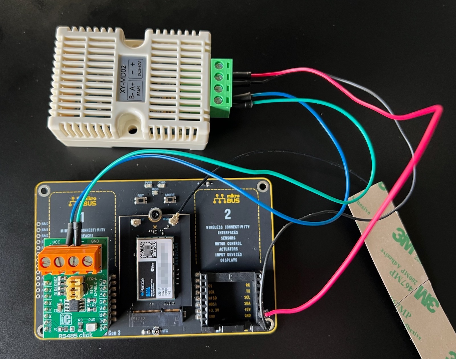
The Particle platform in this application is the B-Series SoM, B404 and the Modbus server is a temperature and humidity sensor. To interface with Modbus over RS-485, typically a Physical Layer Device (PHY) is needed to translate 3.3V TTL level UART lines with the RS-485 bus. This is achieved by using the RS485 Click 3.3V in combination with the Mikroe SoM Shield. Below is a visual representation of the Modbus network along with a picture of the example application.

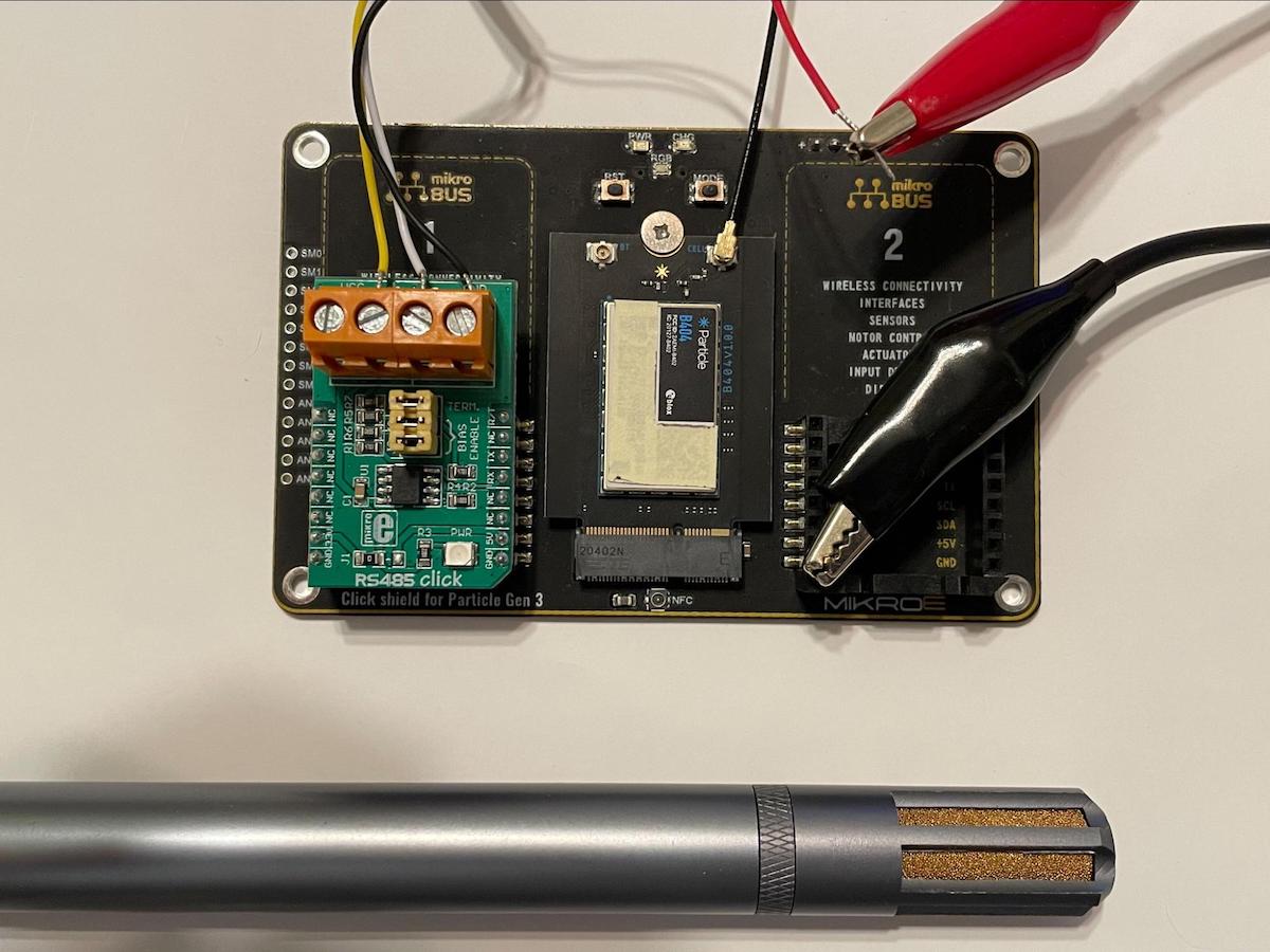
This temperature and humidity sensor operates from 12V to 36V and an external power supply is needed to power the sensor.
There are many different Modbus temperature/humidity sensors. This one has the advantage of working from 5 to 30VDC, so it can be powered from the +5V output of the Mikroe SoM shield when powered by USB.
Additional pinout information for the Mikroe SoM shield can be found in the Mikroe guide.
Transmit pin
The PHY device typically gives access to a transmit pin which disables the received enable functionality during a transmit event. Note that Modbus RTU is a half-duplex protocol meaning only one device on the bus can transmit data at one point in time. If the transmit pin is not enabled and the Client is transmitting, data sent will be mirrored into the receive buffer.
Example firmware
Here is the project firmware:
The goal of the firmware is to implement Modbus RTU in a simple way. This is achieved by leveraging the ModbusMaster library which is a community library that was a port from an existing Arduino library. The example code will read the temperature and humidity from the sensor and publish the data to the cloud.
To use this library, you need to initialize communication by selecting the serial port used (Serial1) and setting the server address (1 in this example). This is achieved by using ModbusMaster node() and this should be done before the setup() and loop() functions. Next, you need to initialize the serial port and this is done by node.begin(). This not only initializes Modbus communication, but it also sets the baud rate.
node.begin(BAUD); //set baud rate for modbus
Your PHY or RS-485 driver will typically include a transmit pin. In this example, we're using pin D5, which is PWM1 on the MikroBUS1. If you are using MikroBUS2 (right side), use D6 instead of D5.
const int RT = D5; //constant for R/T pin set to D5, PWM1 on MikroBUS1
To enable the transmit pin use node.enableTXpin() and call this function in the setup() loop or before the first modbus transaction.
node.enableTXpin(RT); //TX enable pin of RS485 driver
getSensorValue()
To read the temperature and humidity from the sensor, a function was created, getSensorValue(), which handles getting the current temperature and humidity values. This function is simple and uses readHoldingRegisters(). To start the read at the correct register address for the temperature and humidity pass an address of 0 and read two 2 registers worth with the humidity register being the first of the two. The library has error codes built-in to ensure that the transaction was successful so you will want to check the function against the value node.ku8MBSuccess.
int getSensorValues()
{
    //! local variables
    uint16_t data[2];        //create a 2 element array of 16 bit ints
    double tempC;            //variable for temp in celcius

    // readHoldingRegisters and readInputRegisters take two parameters:
    // - the register to start reading from
    // - the number of registers to read (1, 2, ...)

    // Some sensors have the temperature and humidity in holding register 0 and 1. If so, use this version:
    result = node.readHoldingRegisters(0x0000,2);

    // Some sensors have the temperature and humidity in input registers 1 and 2. If so, use this version:
    // result = node.readInputRegisters(1, 2);

    // If you get Modbus Read Error 0x02 (ku8MBIllegalDataAddress), you probably have the wrong register
    // or input/holding selection for your sensor.

    //! read was successful
    if (result == node.ku8MBSuccess)
    {
        //! parse response buffer
        for (uint8_t i = 0; i < 2; i++)
        {
            data[i] = node.getResponseBuffer(i);
        }

        curHum = data[0]/10;                //humidity received divide by 10
        tempC = data[1]/10;                    //temp received divide by 10
        curTemp = (tempC * 1.8) + 32;        //convert celsuis to fahrenheit

        //debug serial messages
        Log.trace("Hum=%.1f (%% RH), Temp=%.1f (C) =%.1f (F)", curHum, tempC, curTemp);

        return SUCCESS;        //return success code
    }

    //! communication failure occured
    else
    {
        //debug serial messages
        Log.info("Modbus Read Error 0x%02x", result);

        return FAIL;        //return fail code
    }
}
Depending on your sensor, the data may be stored different registers.
If your Modbus sensor stores the data in holding register 0 and 1, use this code:
result = node.readHoldingRegisters(0x0000,2);
If your Modbus sensor stores the data in input register 1 and 2, use this code:
result = node.readInputRegisters(1, 2);
The USB serial debug log can help you debug. If you get read error 0x02, you are probably reading the wrong register.
Modbus Read Error 0x02
Particle cloud and functions
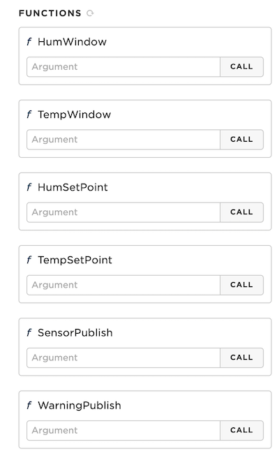
There are 6 Particle functions defined in the example code and each function is used as a way to modify various parameters ranging from temperature/humidity set points, to publish frequencies. These functions are initialized in the setup() loop using Particle.function().
For example, the setHumidityWindow function is used to set the humidity window. The value passed through in conjunction with the humidity set point (via humiditySetpoint()) is used to determine whether the value read from the humidity sensor is outside the range. If outside the range, a warning message is sent to the Particle Cloud via publishWarning() and the frequency is published based on the value set by setWarningFrequency(). If the value is within the range, the current value is sent to the Particle Cloud via publishSensor() and the publish frequency is based on the value set by setPublishFrequency().
By default the humidity window is set to +/- 5% and this value can be modified by passing a new value via the Humidity Window cloud function. When a new value is sent, the value returned will be the new value if the function was successful. Passing a null or blank through the function returns the current humidity window value.
int setHumidityWindow(String value)
{
    //! null case, return current value
    if (value == NULL)
    {
        return humWindow;
    }

    //! update to new value passed and return new value
    else
    {
        humWindow = value.toInt();
        Log.info("humWindow=%d", humWindow);
        return humWindow;
    }
}
The remaining functions, setTemperatureWindow(), temperatureSetpoint(), humiditySetpoint(), setPublishFrequency(), and setWarningFrequency() work in the same way.
Changing settings
The six functions allow you to easily set the values from the Particle console or from the API. Note that this is mainly for demonstration purposes and the settings are not saved. They will revert to the default values when the device is reset.
For example, by increasing the temperature and humidity windows, I was able to eliminate the warning and the temperature and humidity were listed as valid.
Publishing sensor and warning information
The publishSensorValues() function looks like this.
void publishSensorValues()
{
    //! create JSON buffer and write values to it
    JsonWriterStatic<256> jw;
    {
        JsonWriterAutoObject obj(&jw);
        jw.insertKeyValue("Temperature", curTemp);
        jw.insertKeyValue("Humidity", curHum);
        jw.insertKeyValue("Time", Time.format(TIME_FORMAT_ISO8601_FULL));
    }

    Log.info("%s %s", sensorEventName, jw.getBuffer());

    //! send publish only if cloud is connected
    if (Particle.connected() == TRUE)
    {
        Particle.publish(sensorEventName, jw.getBuffer());
    }
}
The data that is published is formatted using JSON format to minimize data operations. This format is machine-readable and mostly human readable. You can learn more about JSON in the JSON tutorial.
It uses the JSONParserGeneratorRK library to simplify the formatting of the data.
The publishWarning() function looks like this:
void publishWarningMessage(int errorCode)
{
    //! create JSON buffer and write values to it
    JsonWriterStatic<256> jw;
    {
        JsonWriterAutoObject obj(&jw);

        if (errorCode == 0)
        {
            jw.insertKeyValue("Warning", "Out of Range");
            jw.insertKeyValue("Temperature", curTemp);
            jw.insertKeyValue("Humidity", curHum);
        }
        else {
            jw.insertKeyValue("Warning", "Modbus Read Error");
            jw.insertKeyValue("ErrorCode", errorCode);
        }
        jw.insertKeyValue("Time", Time.format(TIME_FORMAT_ISO8601_FULL));
        }

    Log.info("%s %s", errorEventName, jw.getBuffer());

    //! send publish only if cloud is connected
    if(Particle.connected() == TRUE)
    {
        Particle.publish(errorEventName, jw.getBuffer() );
    }

}
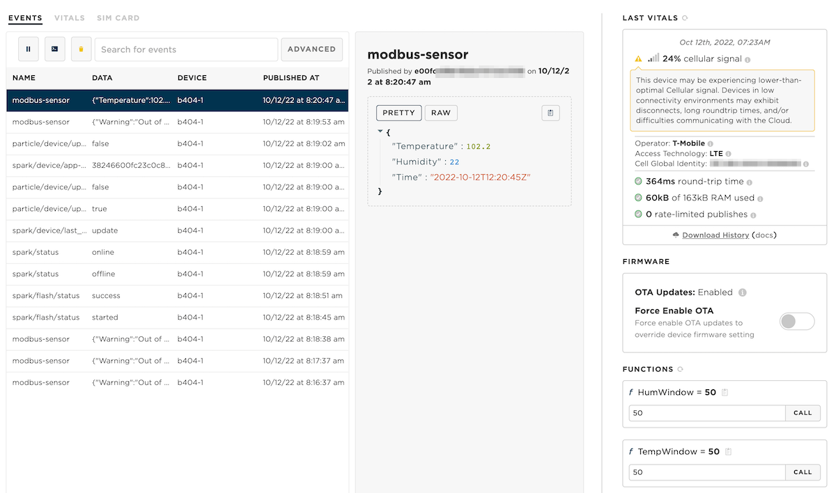
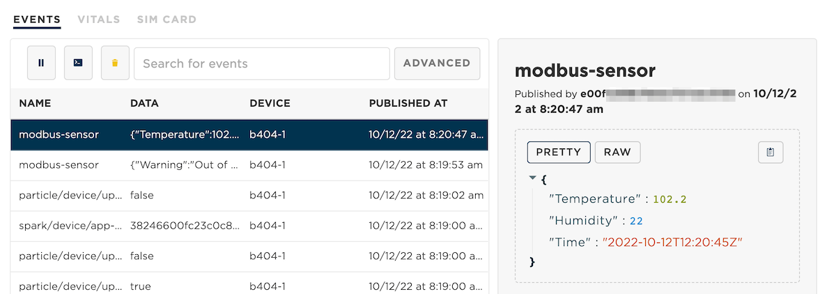
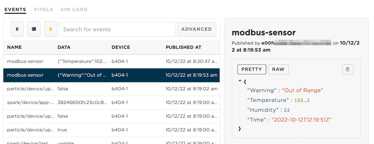
When events are published by the device they look like this in the console:
Temperature or humidity out of range:
If you are viewing the USB serial debug log, the messages look like this:
0000060092 [app] INFO: modbus-sensor {"Warning":"Out of Range","Temperature":102.200000,"Humidity":22.000000,"Time":"2022-10-12T12:19:51Z"}
0000109362 [app] INFO: humWindow=50
0000113543 [app] INFO: tempWindow=50
0000114022 [app] INFO: modbus-sensor {"Temperature":102.200000,"Humidity":22.000000,"Time":"2022-10-12T12:20:45Z"}
0000174111 [app] INFO: modbus-sensor {"Temperature":102.200000,"Humidity":22.000000,"Time":"2022-10-12T12:21:45Z"}
License
This project and about guide is a community contribution from Erik Fasnacht.
The source code is licensed under the MIT license and can be included in both open and closed-source applications, including commercial applications.