
PM-DC power module datasheet
Overview
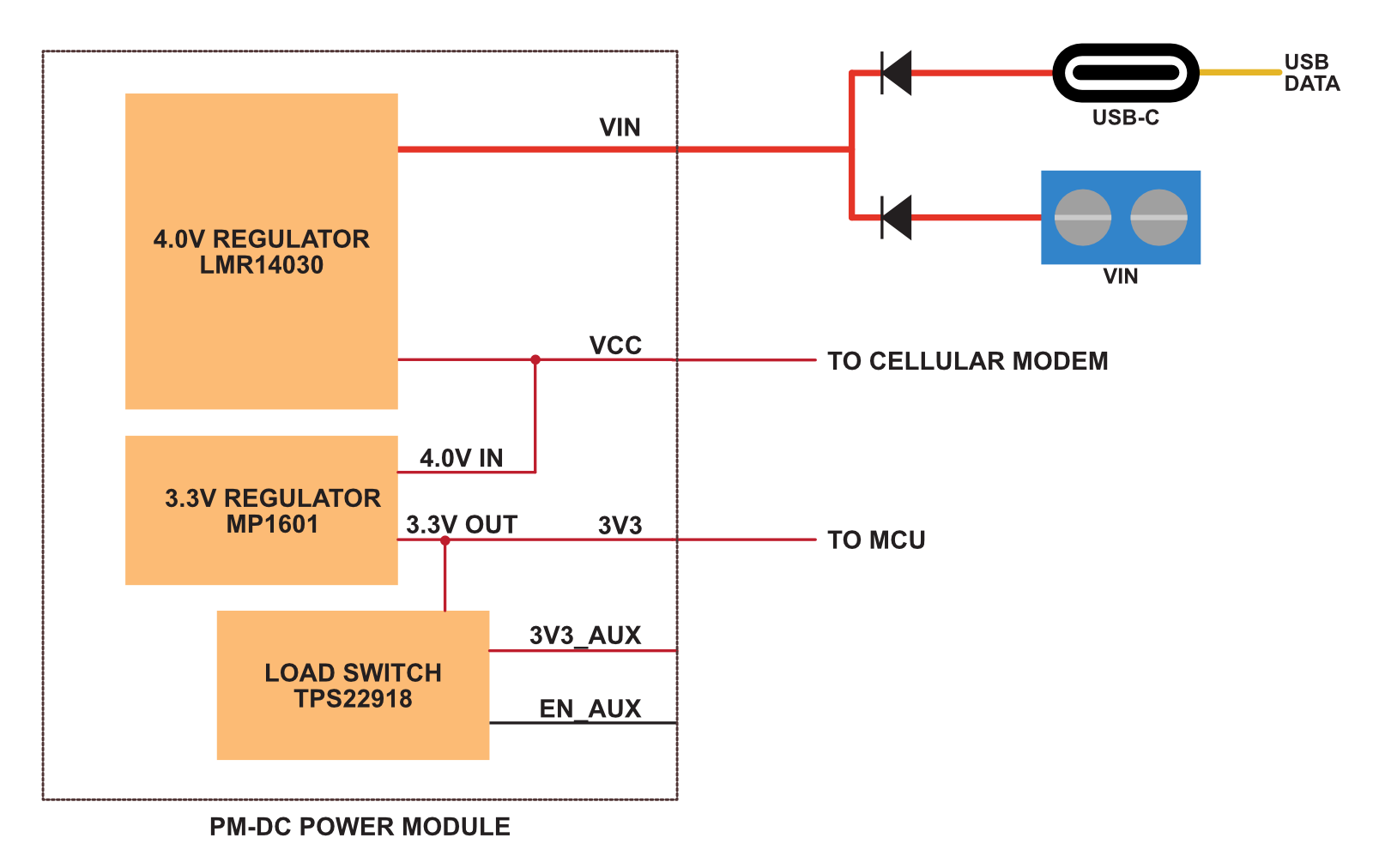
The Particle PM-DC power module is a small module that contains:
- 5 - 12VDC input
- 3.3V regulated output for MCU (1A)
- 4.0V output for cellular modem (2.5A)
It can either be:
- A castellated module intended to be reflow soldered to your M.2 SoM base board
- A module with male pins on the bottom that can be plugged into a socket on your M.2 SoM base board
The PM-BAT power module is also available if you would like support for a LiPo battery as well as DC input.
Block diagram
Dimensions
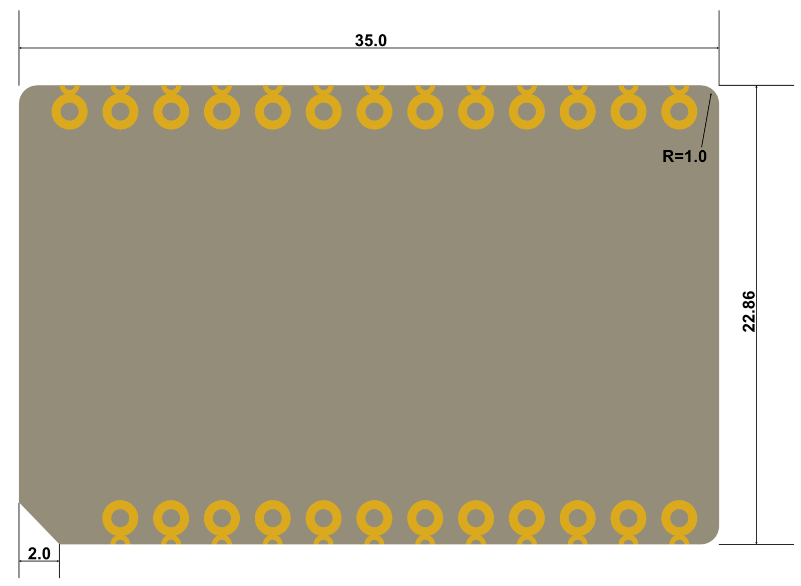
Dimensions in mm
- Module is 35mm x 22.86mm (1.38" x 0.9")
- Pins and castellated holes are 2.54mm (0.1") apart
Pinout

| Pin | Pin Name | Description |
|---|---|---|
| 1 | 3V3 | Power output 3.3V |
| 2 | 3V3_AUX | Power output 3.3V, controllable |
| 3 | 5V | Power output 5V (not available on this module) |
| 4 | 5V | Power output 5V (not available on this module) |
| 5 | VCC | Power output 3.9V 2A for cellular modem |
| 6 | VCC | Power output 3.9V 2A for cellular modem |
| 7 | EN_AUX | Enable 33_AUX (has 100K pull-down to default off) |
| 8 | NC | Leave unconnected |
| 9 | GND | Ground |
| 10 | GND | Ground |
| 11 | VIN | Power in (5V - 12V) |
| 12 | VIN | Power in (5V - 12V) |
| 13 | NC | Leave unconnected (charge indicator on PM-BAT) |
| 14 | NC | Leave unconnected (SCL on PM-BAT) |
| 15 | NC | Leave unconnected (SDA on PM-BAT) |
| 16 | NC | Leave unconnected (FUEL_INT on PM-BAT) |
| 17 | NC | Leave unconnected (temperature sensor on PM-BAT) |
| 18 | NC | Leave unconnected (VBAT on PM-BAT) |
| 19 | NC | Leave unconnected (VBAT on PM-BAT) |
| 20 | NC | Leave unconnected (VBAT on PM-BAT) |
| 21 | GND | Ground |
| 22 | GND | Ground |
| 23 | NC | Leave unconnected (MCU reset on PM-BAT) |
| 24 | NC | Leave unconnected (power good on PM-BAT) |
| 25 | ENABLE | Power output enable. Has internal pull-up to VSYS, pull to GND to disable power outputs. |
3V3_AUX is powered by 3V3 via a load switch (TPS22918). It can supply up to the full 2A of 3V3. It defaults to off due to a pull-down resistor on the pin. Pull to 3V3 to enable the 3V3_AUX output.
If your base board is designed for the PM-BAT power module, you can substitute the PM-DC and the PM-DC power module will function properly, but features such as power management, battery input, charge LED, etc. will not be available, of course.
Firmware settings
Devices using the Particle Power Module include a 3V3_AUX power output
that can be controlled by a GPIO. On the M.2 SoM breakout board, this powers the Feather connector. On the Muon,
it powers the Ethernet port and LoRaWAN module.
The main reason for this is that is with PM-BAT, until the PMIC is configured, the input current with no battery
connected is limited to 100 mA. This is insufficient for the M-SoM to boot when
using a peripheral that requires a lot of current, like the WIZnet W5500 Ethernet module. The
system power manager prevents turning on 3V3_AUX until after the PMIC is configured
and the PMIC has negotiated a higher current from the USB host (if powered by USB).
This is typically less of an issue with PM-DC, however, it will reduce the inrush current at boot and is provided for compatibility with PM-BAT.
After changing the auxiliary power configuration you must reset the device.
The following code can be used to enable Ethernet on the M.2 SoM breakout board. This only needs to be done once and the device must be reset after configuration for the changes to take effect. It requires Device OS 5.9.0 or later.
// Enable 3V3_AUX
SystemPowerConfiguration powerConfig = System.getPowerConfiguration();
powerConfig.auxiliaryPowerControlPin(D23).interruptPin(A6);
System.setPowerConfiguration(powerConfig);

// Enable Ethernet
if_wiznet_pin_remap remap = {};
remap.base.type = IF_WIZNET_DRIVER_SPECIFIC_PIN_REMAP;

System.enableFeature(FEATURE_ETHERNET_DETECTION);
remap.cs_pin = D5;
remap.reset_pin = PIN_INVALID;
remap.int_pin = PIN_INVALID;
auto ret = if_request(nullptr, IF_REQ_DRIVER_SPECIFIC, &remap, sizeof(remap), nullptr);
Land pattern (SMD)
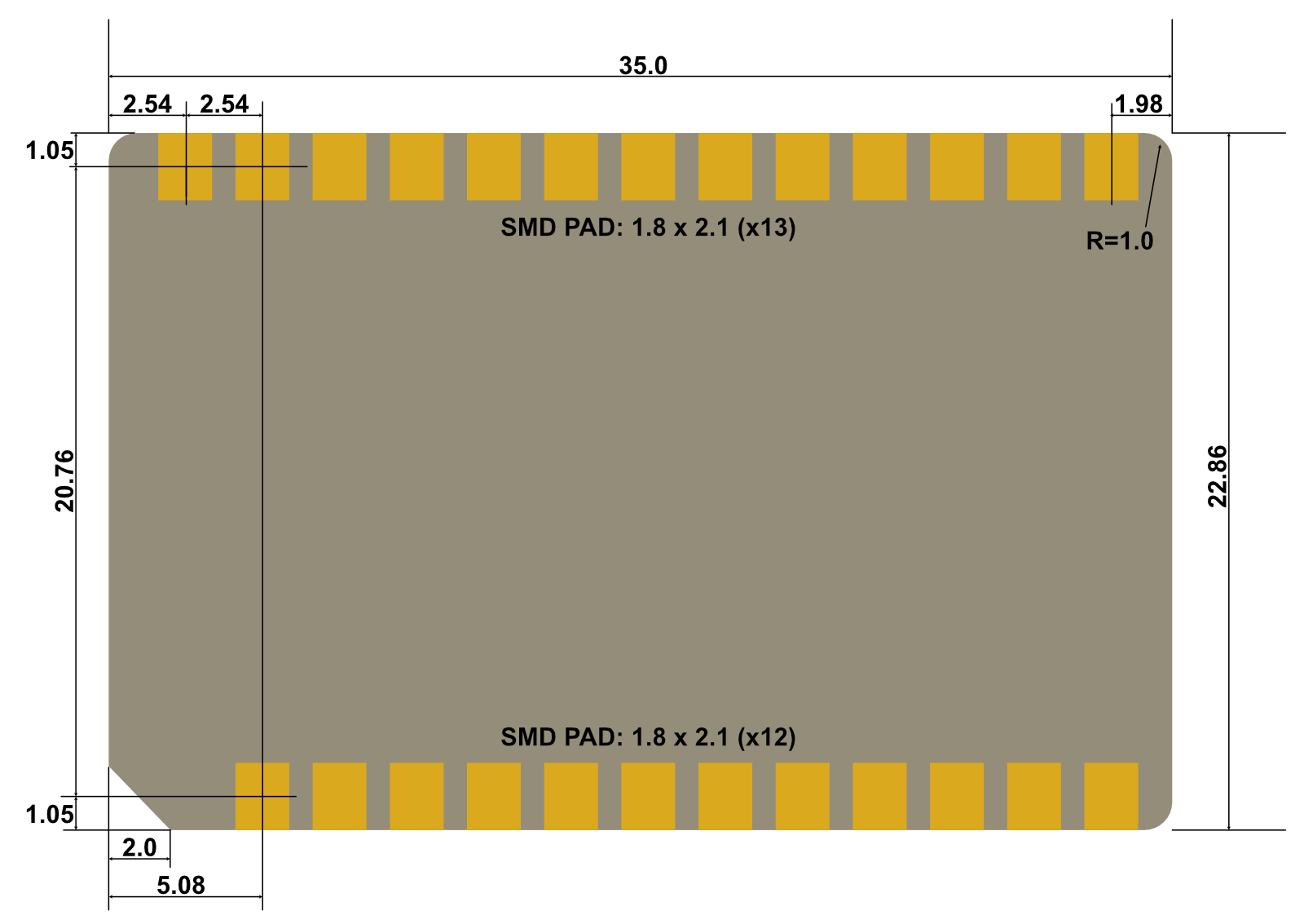
Dimensions in mm
Pin layout
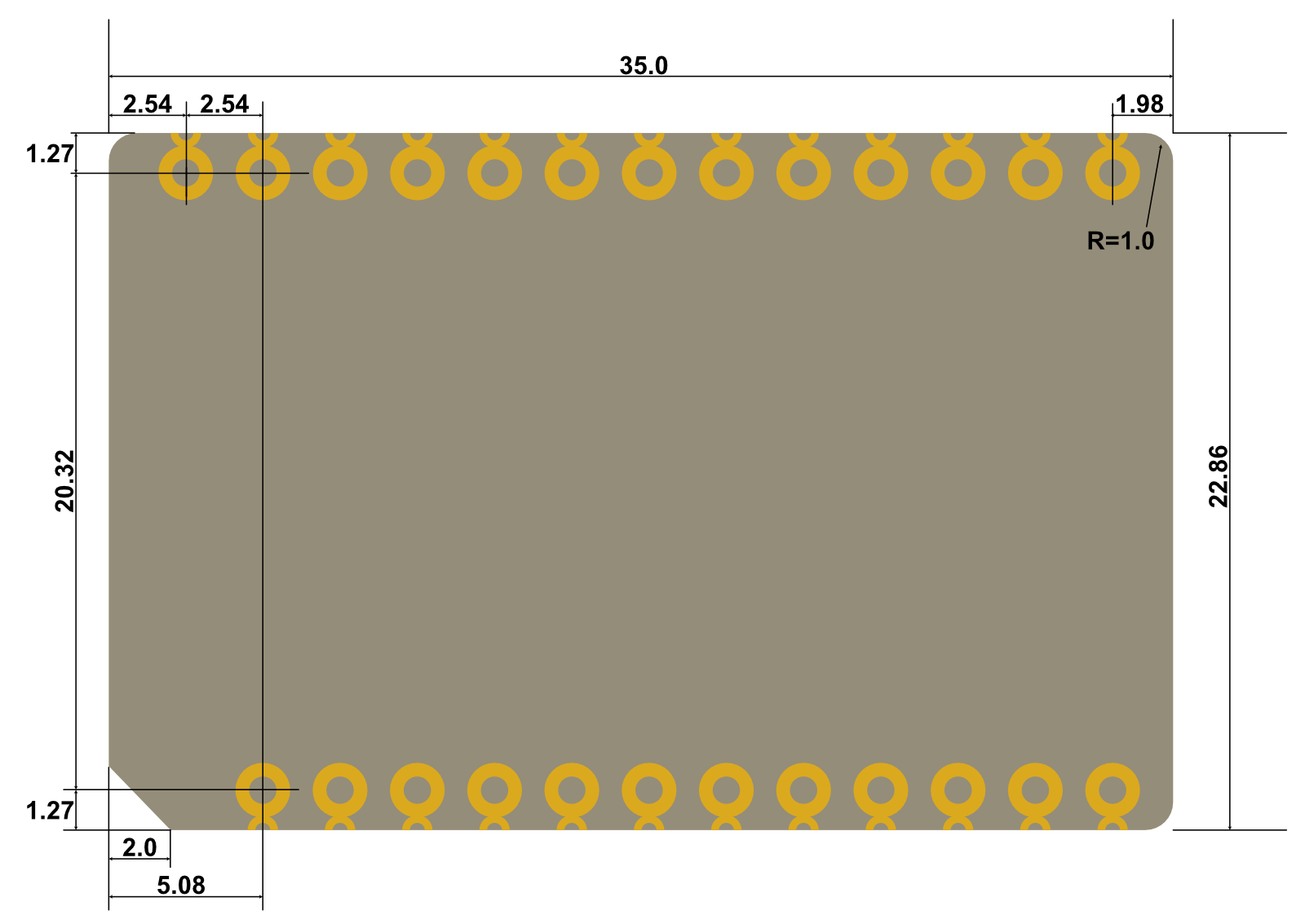
Dimensions in mm
- Male header pins are 0.1" spacing, 12 or 13 pins per side
- Two rows, spaced 0.8" (20.32mm) apart
The mating header is available from a large number of suppliers in both PTH and SMD styles.
| Style | Manufacturer | Model | Example |
|---|---|---|---|
| PTH (12) | Sullins | PPTC121LFBN-RC | Digikey |
| PTH (13) | Sullins | PPTC131LFBN-RC | Digikey |
| SMD (12) | Sullins | NPTC121KFXC-RC | Digikey |
| SMD (13) | Sullins | NPTC131KFXC-RC | Digikey |
Schematic

Ordering information
| SKU | Description | Lifecycle |
|---|---|---|
| PMDCH1EA | Particle Power Module, DC, with Header [x1] | GA |
| PMDCH1TY | Particle Power Module, DC, with Header [x50] | GA |
| PMDCNH1EA | Particle Power Module, DC, No Header | In development |
| PMDCNH1TY | Particle Power Module, DC, without Header [x50] | GA |
Version history
| Revision | Date | Author | Comments |
|---|---|---|---|
| pre | 2024-04-15 | RK | Pre-release |
| 001 | 2024-06-27 | RK | Initial version |
| 002 | 2024-08-08 | RK | Input voltage range is 5-12 VDC |
| 003 | 2024-09-18 | RK | Add firmware settings |
| 004 | 2025-01-08 | RK | Fixed input voltage in table |