
Tracker 4-20mA sensor quad
You can download the files associated with this app note as a zip file.
This application note includes hardware and software for connecting up to four 4-20mA sensors to the Tracker One using the M8 connector.
The quad port design requires an external 12V power supply, but this power supply can also power the Tracker One. It includes a boost converter to 24VDC for the 4-20mA current loop and separate current limiters for each current loop. It uses an external I2C ADC connected to the M8 connector.
There is also a simple single current loop design that can be powered off the built-in LiPo battery.
- 24V boost converter (from external 12V supply)
- 30 mA current limiter per sensor loop
- TVS protection
- I2C Quad ADC (ADS1015)
- 3.3V power supply for the ADC (from CAN_5V)
Connecting
The M8 (8mm) 8-pin connector on the Tracker One is standard, however it's not common. Some other connectors like M12 are more common, however, the 12mm connector would have required a taller enclosure to fit the larger connector. To simplify designs, Particle will provide a M8 female-to-wires cable, similar to this. This is for illustration only and the design may vary in the future.
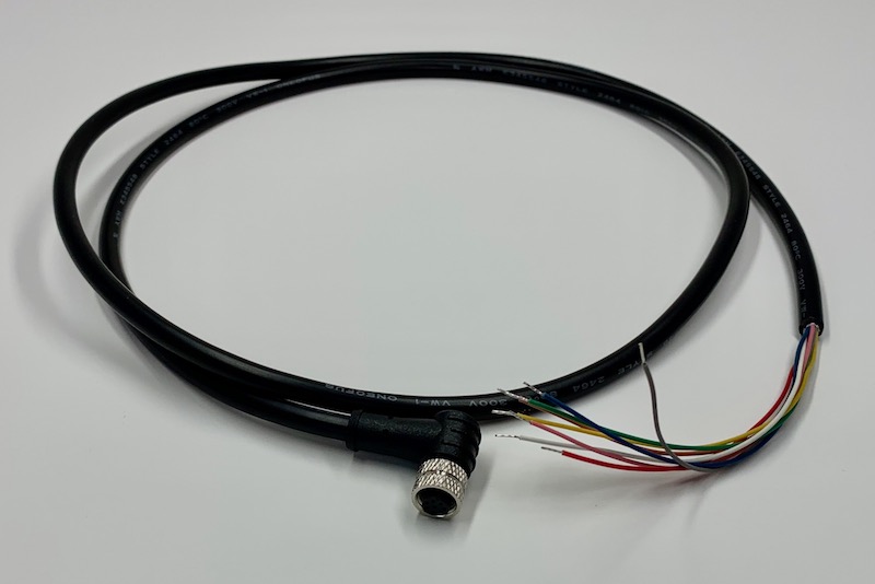
The common use case will be to include a cable gland in your expansion enclosure, pass the wires through the gland, and terminate them on your custom expansion board.
You'd typically connect those wires to your custom expansion board using one of several methods:
- Terminate with pins in a PHR-8 to mate with a B8B-PH on your expansion board
- Terminate with screw terminals on your board
- Terminate by soldering the wires to your board
This example can be used three different ways:
It can use the same B8B-PH connector that is inside the Tracker One on the Tracker Carrier board. This connector is inexpensive and can be attached directly to the Tracker One Carrier Board.
Or you can populate a 8x0.1" screw terminal header. This is good for connecting to the M8 to flying leads.
Or you can populate 0.1" male header pins, which are handy for use with male-to-female Dupont wires for connecting directly to the Tracker SoM evaluation board.
Hardware - quad
Schematic - quad
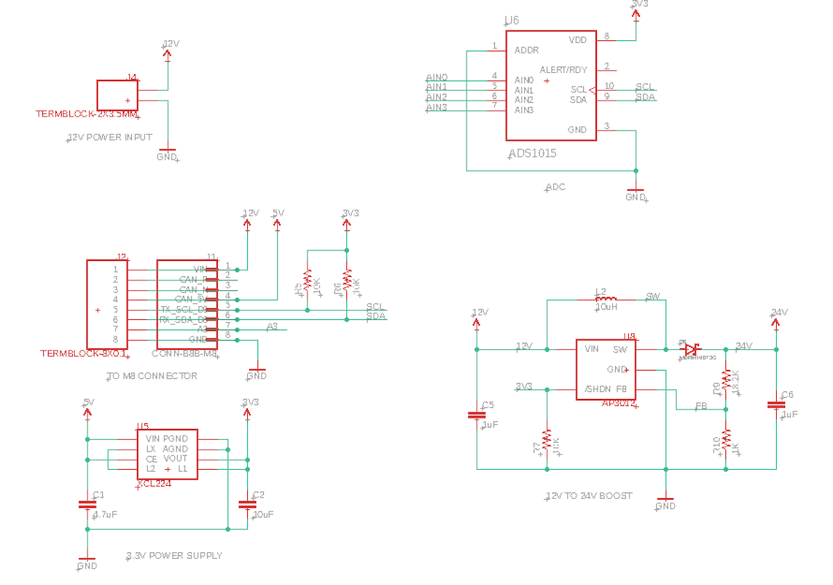
Unlike the previous design, this one requires a 3.3V power supply for the I2C ADC. The I2C and Serial ports as well as GPIO and ADC on the nRF52 are limited to 3.3V. An XCL224 regulator is included. It's small, relatively inexpensive, and only requires 4.7uF and 10 uF capacitors. It does not require an inductor, saving cost and space.
The ADC is a ADC1015, a quad I2C ADC. In order to support 4 channels it's used in single-ended mode.
4-20mA generally requires 24VDC. We generate this from the CAN_5V supply using a AP3012 boost converter. This inexpensive chip only requires input and output capacitor, a Schottky diode, an inductor, and two resistors for a voltage divider to control the output voltage. Though the other design uses a MIC2288, that chip can't handle a 12V input. The other design could be easily modified to use the AP3012 if desired, even the voltage divider resistors are identical.
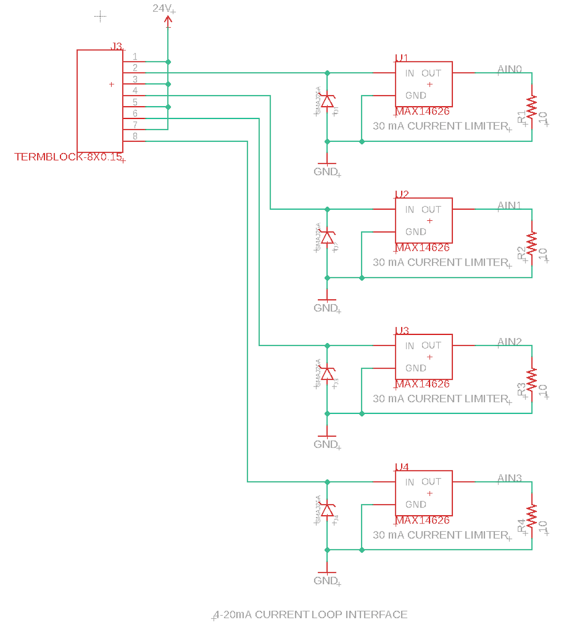
The sensing circuit is identical to the single, but there are 4 of them.
The sense resistor is connected low-side, to ground, so it can be measured with a single-ended ADC.
This design uses a 10 ohm sense resistor, since the ADS1015 has programmable gain control. The ADS 1015 is run in PGA16 mode (+/- 0.256V).
| Current | ADC Value | Description |
|---|---|---|
| 0 mA | 0 | Open Circuit |
| 4 mA | 318 | Minimum Value |
| 20 mA | 1602 | Maximum Value |
| 30 mA | 2048 | Short circuit |
Originally, I used a 100 ohm resistor is used so the maximum current of 30 mA will have a voltage of 3.0V across the sense resistor, within the capabilities of the ADC but using 10 ohm uses more of the usable range of the ADC. For the 100 ohm sense resistor, the ADS 1015 is run in PGA1 mode (+/-4.096V). This means 3.3V is approximately 1652.
| Current | Voltage | ADC Value | Description |
|---|---|---|---|
| 0 mA | 0.0 V | 0 | Open Circuit |
| 4 mA | 0.4 V | 199 | Minimum Value |
| 20 mA | 2.0 V | 1004 | Maximum Value |
| 30 mA | 3.0 V | 1506 | Short circuit |
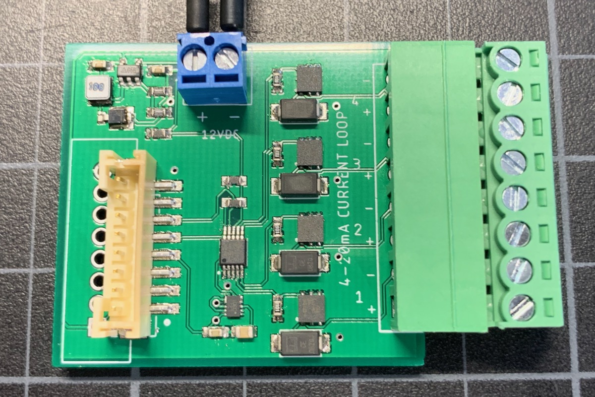
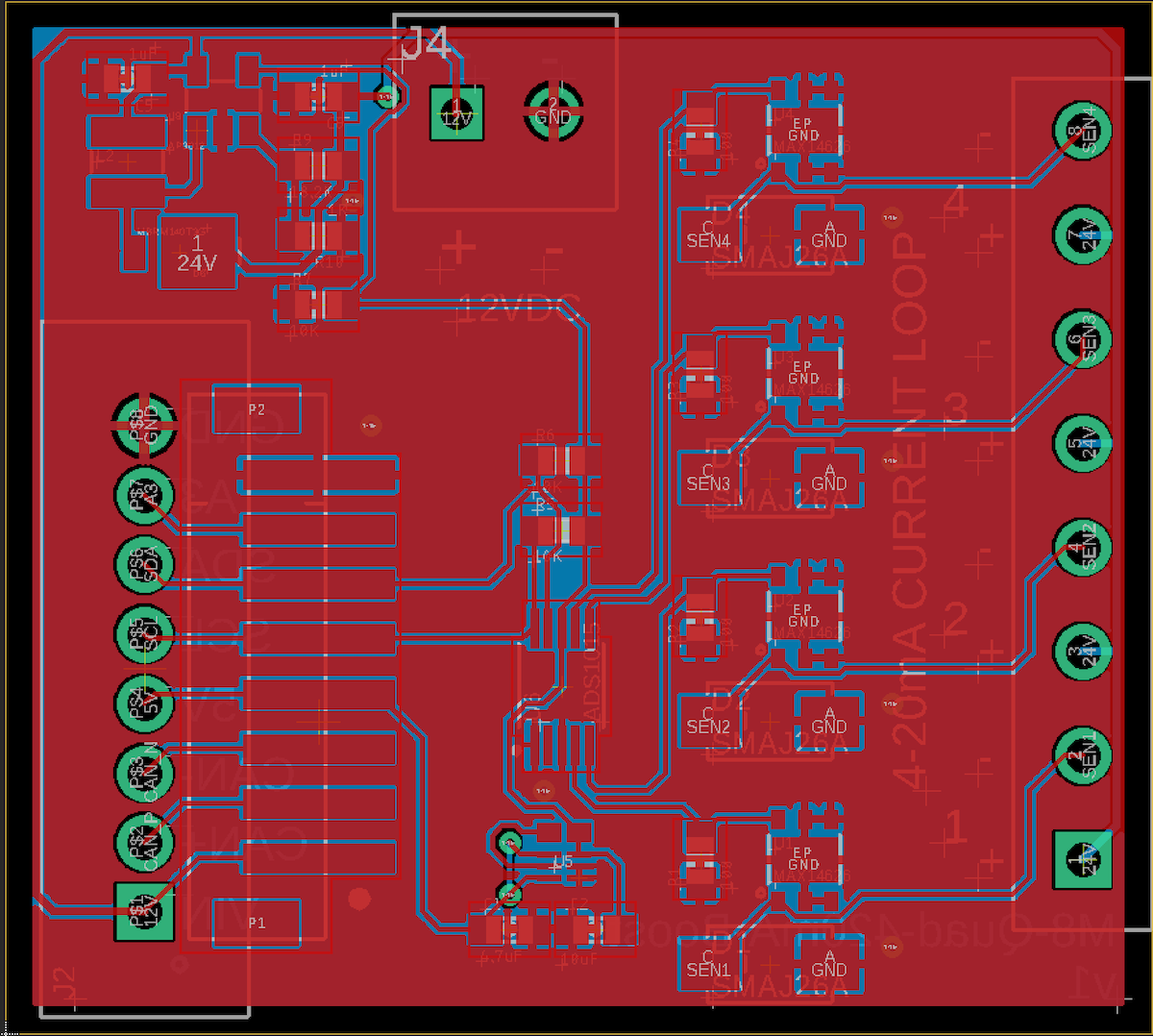
Board layout - quad
BoM (Bill of Materials) - quad
| Quantity | Part | Description | Example | Cost |
|---|---|---|---|---|
| 1 | C1 | CAP CER 4.7UF 6.3V X5R 0603 | Murata GRM188R60J475KE19J | |
| 1 | C2 | CAP CER 10UF 16V X5R 0805 | Murata GRM21BR61C106KE15L | |
| 2 | C5, C6 | CAP CER 1UF 25V X7R 0603 | Samsung CL10B105KA8NNNC | |
| 4 | D1 - D4 | TVS DIODE 26V 42.1V DO214AC | Littelfuse SMAJ26A | $0.36 |
| 1 | D6 | DIODE SCHOTTKY 40V 1A POWERMITE | ON Semiconductor MBRM140T3G | $0.36 |
| 1 | J4 | TERM BLK 2POS SIDE ENT 3.5MM | On Shore OSTTE020161M | $0.67 |
| 1 | L1 | FIXED IND 10UH 1A 276 MOHM SMD | Bourns SRN3015-100M | $0.46 |
| 4 | R1 - R4 | RES SMD 10 OHM 1% 1/10W 0603 | Panasonic ERJ-3EKF10R0V | |
| 3 | R5, R6, R7 | RES SMD 10K OHM 5% 1/4W 0603 | Panasonic ERJ-PA3J103V | |
| 1 | R9 | RES SMD 18.2K OHM 0.1% 1/5W 0603 | Panasonic ERJ-PB3B1822V | $0.25 |
| 1 | R10 | RES SMD 1K OHM 0.5% 1/5W 0603 | Panasonic ERJ-PB3D1001V | |
| 4 | U1 - U4 | IC CURR LOOP PROT 4-20MA 6TDFN | Maxim MAX14626ETT+T | $1.32 |
| 1 | U5 | XCL224 3.3V regulator | Torex XCL224A333D2-G | $ 2.43 |
| 1 | U6 | IC ADC 4-ch 12-bit I2C 10-VSSOP | TI ADS1015IDGSR | $2.68 |
Choose one of:
| Quantity | Part | Description | Example | Cost |
|---|---|---|---|---|
| 1 | J3 | Conn SMD 8 position 2.00mm | JST B8B-PH-SM4-TB(LF)(SN) | $1.00 |
| J7 | Male Header Pins (8x0.1") | Sullins PRPC040SAAN-RC | ||
| 1 | J7 | Screw Terminal Block 8x0.1" PTH | On Shore OSTVN08A150 | $2.36 |
The part shown in the picture above is the detachable screw terminal header. This is handy because you can detach the adapter board without having to unscrew all 8 screw terminal connectors, however it is more expensive. Another alternative is to use a standard screw terminal header, the second option. You only need one or the other.
| Quantity | Part | Description | Example | Cost |
|---|---|---|---|---|
| Option 1: | ||||
| 1 | J3 | TERM BLOCK HDR 8POS 90DEG 3.81MM | On Shore OSTOQ083251 | $1.35 |
| 1 | TERM BLOCK PLUG 8POS STR 3.81MM | On Shore OSTTJ0831530 | $3.29 | |
| Option 2: | ||||
| 1 | J3 | TERM BLK 8P SIDE ENT 3.81MM PCB | Amphenol YO0821500000G | $1.79 |
By the way, this inexpensive tool from Amazon ($27.99) is very handy for testing 4 - 20mA. It's powered by USB and you dial in the exact number of mA you want to draw.
Firmware
Getting the Tracker Edge firmware
You can download a complete project for use with Particle Workbench as a zip file here:
Version:
- Extract tracker-an021.zip in your Downloads directory
- Open the tracker-an021 folder in Workbench using File - Open...; it is a pre-configured project directory.
- From the Command Palette (Command-Shift-P or Ctrl-Shift-P), use Particle: Configure Project for Device.
- If you are building in the cloud, you can use Particle: Cloud Flash or Particle: Cloud Compile.
- If you are building locally, open a CLI window using Particle: Launch CLI then:
particle library copy
Manually
The Tracker Edge firmware can be downloaded from GitHub:
https://github.com/particle-iot/tracker-edge
You will probably want to use the command line as there are additional commands you need to run after cloning the source:
git clone https://github.com/particle-iot/tracker-edge
cd tracker-edge
git submodule update --init --recursive
- Open Particle Workbench.
- From the command palette, Particle: Import Project.
- Run Particle: Configure Workspace for Device, select version 1.5.4-rc.1, 2.0.0-rc.3, or later, Tracker, and your device.
- Run Particle: Flash application (local).
Make sure you've used the Mark As Development Device option for your Tracker device in your Tracker product. If you don't mark the device as a development device it will be flashed with the default or locked product firmware version immediately after connecting to the cloud, overwriting the application you just flashed.
Add the libraries
From the command palette in Workbench, Particle: Install Library then enter Sensor_4_20mA_RK. Repeat for SparkFun_ADS1015_Arduino_Library.
If you prefer to edit project.properties directly, add these:
The full source
Digging in - quad
const size_t NUM_SENSOR_CONFIG = 2;
SensorConfig sensorConfig[NUM_SENSOR_CONFIG] = {
    { 100, "sen1" },
    { 101, "sen2", 0, 100, false }
};

Sensor_4_20mA sensor;
This configures two sensors on the ADS1015 I2C ADC.
Virtual sensor pin 100 (an arbitrarily defined number) saves the data to the key "sen1" in location publishes. The value will be in mA.
Virtual sensor pin 101 (the second port) is connected to a 0-100°C 4-20mA RTD temperature sensor I got from Amazon.
The next parameters are the range of the sensor (0 to 100). The false parameter indicates that the lower bound is the value for 0 mA, not 4 mA.
| Last Parameter | Meaning |
|---|---|
| false | Lower value is value for 0 mA |
| true | Lower value is the value for 4 mA (default) |
More information about the configuration object can be found in the 4-20mA library GitHub.
sensor
    .withADS1015(100, ADS1015_CONFIG_PGA_16, 318, 1602, ADS1015_ADDRESS_GND, Wire3)
    .withConfig(sensorConfig, NUM_SENSOR_CONFIG)
    .init();
The parameters to withADS1015() are:
Since the ADC1015 ADCs don't have pin numbers (in the analogRead() sense), we assign them virtual pin numbers, which typically start at 100. They don't need to be contiguous. Each ADS1015 has 4 ADCs, so it always uses 4 virtual pins, even if you don't use all 4 ADCs. An 8-channel ADC would use 8. The value 100 is the virtual pin number to start with for that ADC. This must match the config structure, above.
ADS1015_CONFIG_PGA_16is the gain setting for the ADC for a 10 ohm sense resistor.318 is the ADC value for 4 mA (
adcValue4mA) when using a 10 ohm sense resistor. See table below.1602 is the ADC value for 20 mA (
adcValue20mA).
| Parameter | 10 ohm | 100 ohm |
|---|---|---|
gain |
ADS1015_CONFIG_PGA_16 |
ADS1015_CONFIG_PGA_1 |
adcValue4mA |
318 | 199 |
adcValue20mA |
1602 | 1004 |
void myLocationGenerationCallback(JSONWriter &writer, LocationPoint &point, const void *context)
{
    sensor.writeJSON(writer);
}
This adds the keys defined in the SensorConfig to the location publishes.
Revision history
0.0.2 (2020-08-11)
- Changed the sense resistor from 100 ohm to 10 ohm, since the ADS1015 has built-in gain control