
Tracker 4-20mA sensor
You can download the files associated with this app note as a zip file.
This application note includes hardware and software for connecting a single 4-20mA current loop sensor to the Tracker One using the M8 connector.
The single port design can be powered by the built-in LiPo battery or USB and uses the built-in ADC on the nRF52840, available on the M8 connector. It includes a boost converter to 24VDC for the 4-20mA current loop. It includes over-current protection, limiting the 4-20mA loop to 30 mA.
- 24V boost converter (from CAN_5V)
- 30 mA current limiter
- TVS protection
There is also an application note with support for 4 current loops.
Connecting
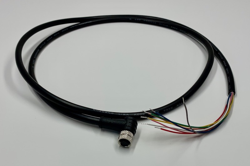
The M8 (8mm) 8-pin connector on the Tracker One is standard, however it's not common. Some other connectors like M12 are more common, however, the 12mm connector would have required a taller enclosure to fit the larger connector. To simplify designs, Particle will provide a M8 female-to-wires cable, similar to this. This is for illustration only and the design may vary in the future.
The common use case will be to include a cable gland in your expansion enclosure, pass the wires through the gland, and terminate them on your custom expansion board.
You'd typically connect those wires to your custom expansion board using one of several methods:
- Terminate with pins in a PHR-8 to mate with a B8B-PH on your expansion board
- Terminate with screw terminals on your board
- Terminate by soldering the wires to your board
This example can be used three different ways:
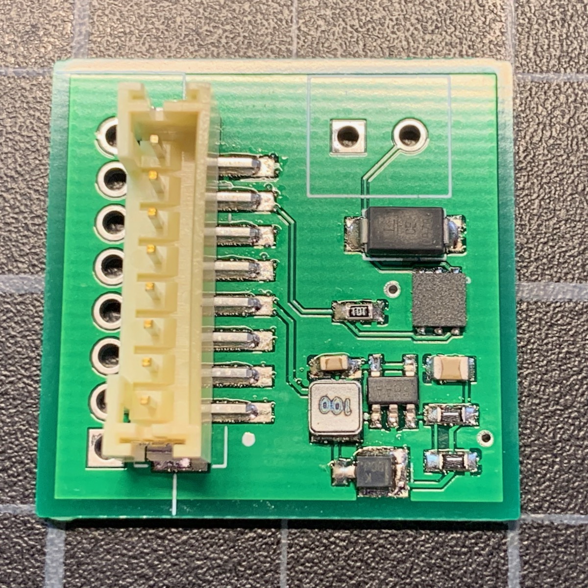
It can use the same B8B-PH connector that is inside the Tracker One on the Tracker Carrier board. This connector is inexpensive and can be attached directly to the Tracker One Carrier Board.
Or you can populate a 8x0.1" screw terminal header. This is good for connecting to the M8 to flying leads.
Or you can populate 0.1" male header pins, which are handy for use with male-to-female Dupont wires for connecting directly to the Tracker SoM evaluation board.
Hardware - single
Schematic - single
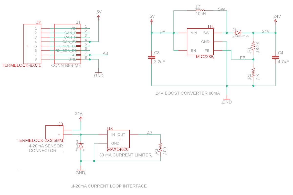
The single design only uses CAN_5V to power, and uses pin A3 as an analog input. Unlike most of the other designs, this does not require a 3.3V regulator or use the I2C/serial pins.
4-20mA generally requires 24VDC. We generate this from the CAN_5V supply using a MIC2288 boost converter. This inexpensive chip only requires input and output capacitor, a Schottky diode, an inductor, and two resistors for a voltage divider to control the output voltage. Because of the large amount of boost, this design can only supply 80 mA at 24V.
The sensing loop has the 4-20mA sensor high-side, connected to the 24 volt supply. A TVS diode (SMAJ26A) protects against voltage spikes and high voltages.
A MAX14626 limits the current to 30mA. Even if you short the sensor connection, it will still limit the current to 30 mA, preventing damage to the boost converter and the sense resistor.
The sense resistor is connected low-side, to ground, so it can be measured with a single-ended ADC. A 100 ohm resistor is used so the maximum current of 30 mA will have a voltage of 3.0V across the sense resistor, within the capabilities of the ADC.
| Current | Voltage | ADC Value | Description |
|---|---|---|---|
| 0 mA | 0.0 V | 0 | Open Circuit |
| 4 mA | 0.4 V | 491 | Minimum Value |
| 20 mA | 2.0 V | 2469 | Maximum Value |
| 30 mA | 3.0 V | 3723 | Short circuit |
The connection to the sensor is via a 2 screw-terminal header.
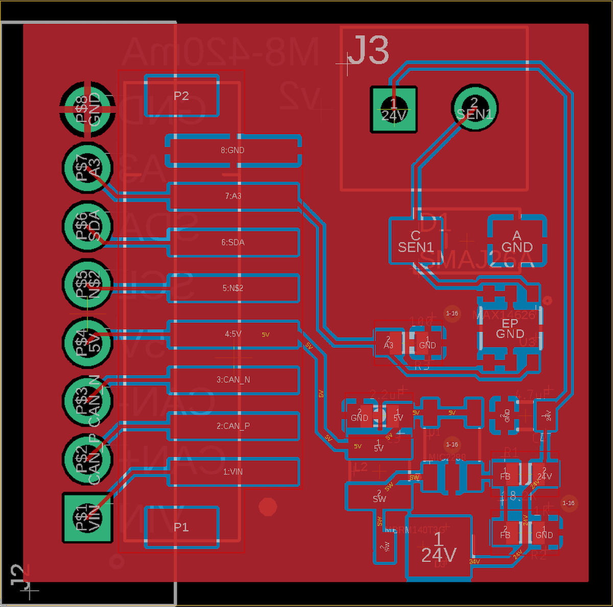
Board layout - single
BoM (Bill of Materials) - single
| Quantity | Part | Description | Example | Cost |
|---|---|---|---|---|
| 1 | C3 | CAP CER 2.2UF 25V X5R 0603 | Murata GRM188R61E225KA12D | |
| 1 | C4 | CAP CER 4.7UF 6.3V X5R 0603 | Murata GRM188R60J475KE19J | |
| 1 | D1 | TVS DIODE 26V 42.1V DO214AC | Littelfuse SMAJ26A | $0.36 |
| 1 | D3 | DIODE SCHOTTKY 40V 1A POWERMITE | ON Semiconductor MBRM140T3G | $0.36 |
| 1 | J3 | TERM BLK 2POS SIDE ENT 3.5MM | On Shore OSTTE020161M | $0.67 |
| 1 | L1 | FIXED IND 10UH 1A 276 MOHM SMD | Bourns SRN3015-100M | $0.46 |
| 1 | R1 | RES SMD 18.2K OHM 0.1% 1/5W 0603 | Panasonic ERJ-PB3B1822V | $0.25 |
| 1 | R2 | RES SMD 1K OHM 0.5% 1/5W 0603 | Panasonic ERJ-PB3D1001V | |
| 1 | R3 | RES SMD 100 OHM 5% 1/10W 0603 | Panasonic ERJ-3GEYJ101V | |
| 1 | U3 | IC CURR LOOP PROT 4-20MA 6TDFN | Maxim MAX14626ETT+T | $1.32 |
Choose one of:
| Quantity | Part | Description | Example | Cost |
|---|---|---|---|---|
| 1 | J3 | Conn SMD 8 position 2.00mm | JST B8B-PH-SM4-TB(LF)(SN) | $1.00 |
| J7 | Male Header Pins (8x0.1") | Sullins PRPC040SAAN-RC | ||
| 1 | J7 | Screw Terminal Block 8x0.1" PTH | On Shore OSTVN08A150 | $2.36 |
By the way, this inexpensive tool from Amazon ($27.99) is very handy for testing 4 - 20mA. It's powered by USB and you dial in the exact number of mA you want to draw.
Firmware
Getting the Tracker Edge firmware
You can download a complete project for use with Particle Workbench as a zip file here:
Version:
- Extract tracker-an020.zip in your Downloads directory
- Open the tracker-an020 folder in Workbench using File - Open...; it is a pre-configured project directory.
- From the Command Palette (Command-Shift-P or Ctrl-Shift-P), use Particle: Configure Project for Device.
- If you are building in the cloud, you can use Particle: Cloud Flash or Particle: Cloud Compile.
- If you are building locally, open a CLI window using Particle: Launch CLI then:
particle library copy
Manually
The Tracker Edge firmware can be downloaded from GitHub:
https://github.com/particle-iot/tracker-edge
You will probably want to use the command line as there are additional commands you need to run after cloning the source:
git clone https://github.com/particle-iot/tracker-edge
cd tracker-edge
git submodule update --init --recursive
- Open Particle Workbench.
- From the command palette, Particle: Import Project.
- Run Particle: Configure Workspace for Device, select version 1.5.4-rc.1, 2.0.0-rc.3, or later, Tracker, and your device.
- Run Particle: Flash application (local).
Make sure you've used the Mark As Development Device option for your Tracker device in your Tracker product. If you don't mark the device as a development device it will be flashed with the default or locked product firmware version immediately after connecting to the cloud, overwriting the application you just flashed.
Add the libraries
From the command palette in Workbench, Particle: Install Library then enter Sensor_4_20mA_RK. If you prefer to edit project.properties directly, add this:
The full source
Digging in
const size_t NUM_SENSOR_CONFIG = 1;
SensorConfig sensorConfig[NUM_SENSOR_CONFIG] = {
    { A3, "temp", 0, 100, false }
};
Sensor_4_20mA sensor;
This configure pin A3 (one of the multi-function pins on the M8 connector). "temp" is the JSON key to include in the location publishes.
In this example, we're using a 0-100°C 4-20mA RTD temperature sensor I got from Amazon.
The next parameters are the range of the sensor (0 to 100). The false parameter indicates that the lower bound is the value for 0 mA, not 4 mA.
| Last Parameter | Meaning |
|---|---|
| false | Lower value is value for 0 mA |
| true | Lower value is the value for 4 mA (default) |
More information about the configuration object can be found in the 4-20mA library GitHub.
sensor
    .withNativeADC()
    .withConfig(sensorConfig, NUM_SENSOR_CONFIG)
    .init();
This is the initialization of the 4-20mA sensor library. It's set to use the native nRF52 ADC (pin A3), with the configuration we defined above.
void mymyLocationGenerationCallback(JSONWriter &writer, LocationPoint &point, const void *context)
{
    sensor.writeJSON(writer);
}
This adds the keys defined in the SensorConfig to the location publishes.