
Tracker tank level sensor
You can download the files associated with this app note as a zip file.
This application note demonstrates several ways you can expand the Tracker One using the M8 connector:
- Adding additional GPIO (adds 3 ports of 3.3V GPIO using a MCP23008)
- Adding additional ADC (adds 3 ADC inputs, 3.3V using an ADS1015 12-bit ADC)
- Support for a tank level sensor (240-33 ohm, common in the US)
- 12V boost converter, for powering low-power 12V sensors (needed for tank sensor)
Connecting
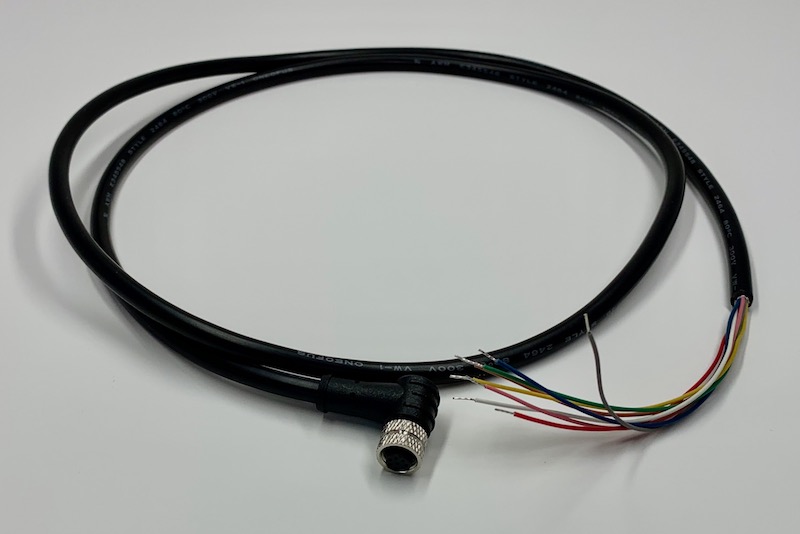
The M8 (8mm) 8-pin connector on the Tracker One is standard, however it's not common. Some other connectors like M12 are more common, however, the 12mm connector would have required a taller enclosure to fit the larger connector. To simplify designs, Particle will provide a M8 female-to-wires cable, similar to this. This is for illustration only and the design may vary in the future.
The common use case will be to include a cable gland in your expansion enclosure, pass the wires through the gland, and terminate them on your custom expansion board.
You'd typically connect those wires to your custom expansion board using one of several methods:
- Terminate with pins in a PHR-8 to mate with a B8B-PH on your expansion board
- Terminate with screw terminals on your board
- Terminate by soldering the wires to your board
This example can be used three different ways:
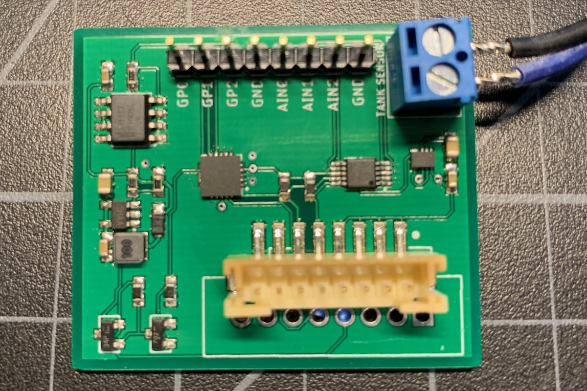
It can use the same B8B-PH connector that is inside the Tracker One on the Tracker Carrier board. This connector is inexpensive and can be attached directly to the Tracker One Carrier Board.
Or you can populate a 8x0.1" screw terminal header. This is good for connecting to the M8 to flying leads.
Or you can populate 0.1" male header pins, which are handy for use with male-to-female Dupont wires for connecting directly to the Tracker SoM evaluation board.
Hardware
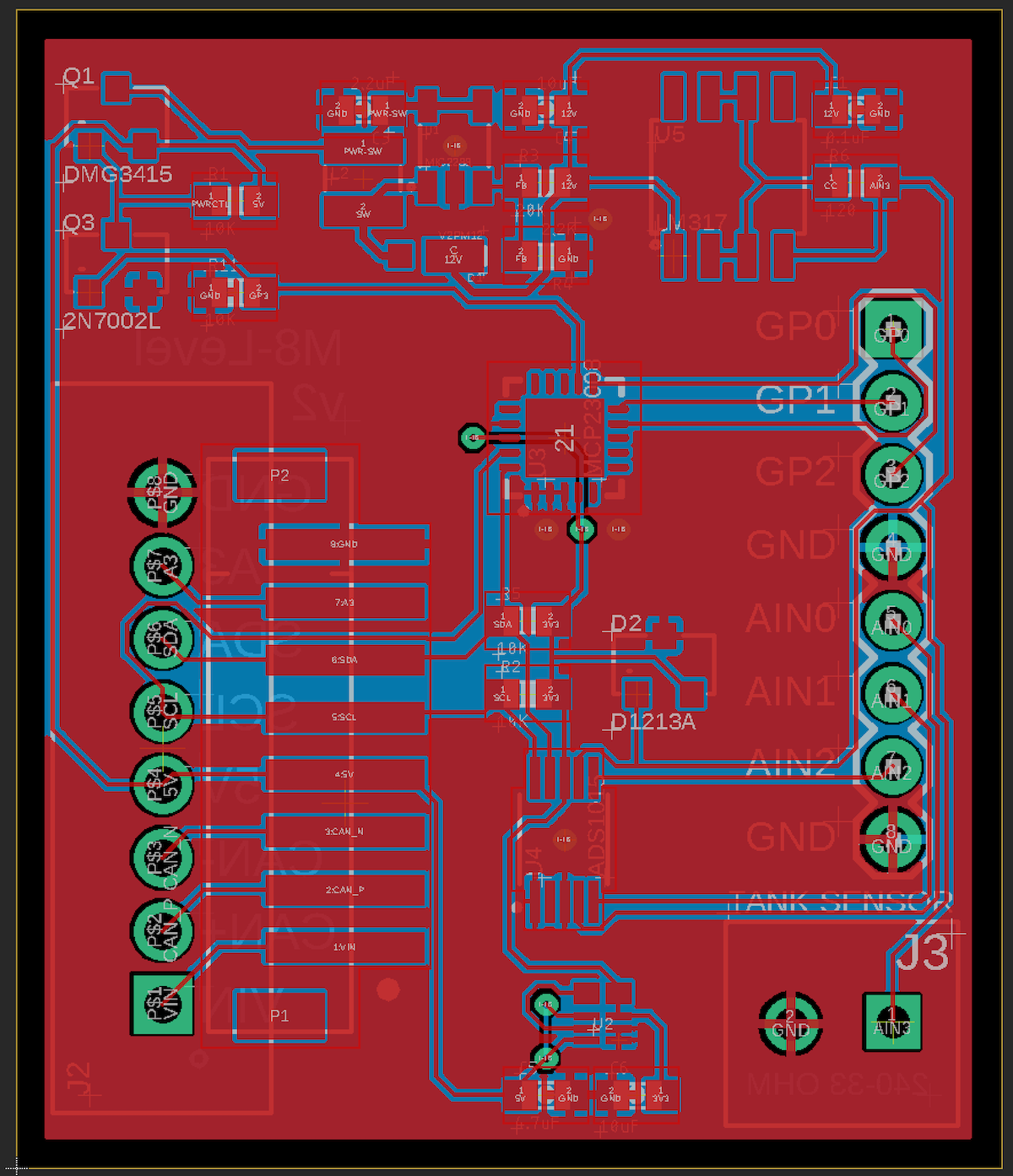
Schematic and board
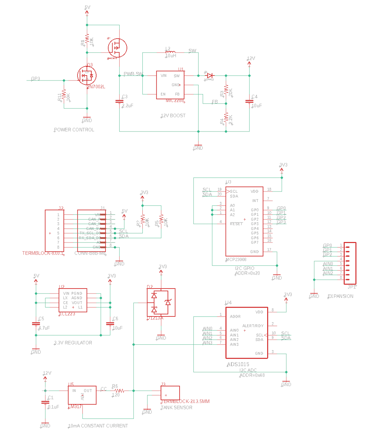
Power and M8 connection
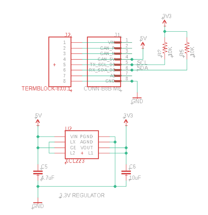
This board is intended to be powered by the M8 connector, which includes the 5V CAN_PWR. This is a controllable boost power supply that supplies 5V at 370 mA even off battery.
Since much of the logic including the nRF52840 GPIO and I2C run only at 3.3V, a 3.3V regulator (XCL224) is included in this design. This regulator is a tiny switching regulator and is nice because it does not require an external inductor, saving space and cost.
The XCL224 is a tiny and does not require an external inductor. It only requires 4.7 uF input and 10 uF output capacitors.
GPIO
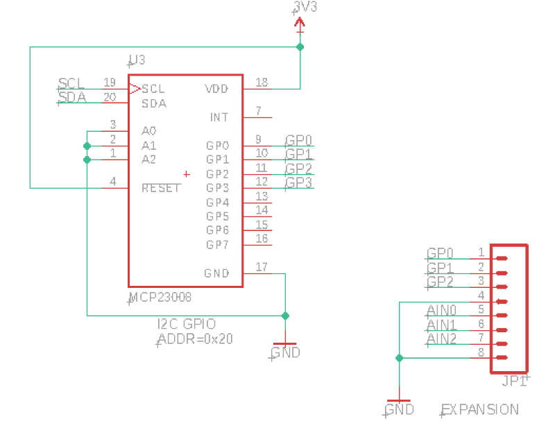
By using the I2C interface on the M8 connector you can easily add additional ports to your expansion device.
This design includes a Microchip MCP23008T-E/ML in a tiny 20-QFN-EP package. The AN013 Tracker GPIO example uses the much larger (but easier to solder) 18-SOIC package. The software is the same for both chip packages. The MCP23008 adds 8 GPIO pins via the I2C interface. This design uses it at 3.3V. The pins can be used as input, input pull-up, or output modes.
GP0, GP1, and GP2 are present on the expansion connector. GP3 is used to control the 12V boost converter.
GP4 - GP7 are not connected in this design.
ADC
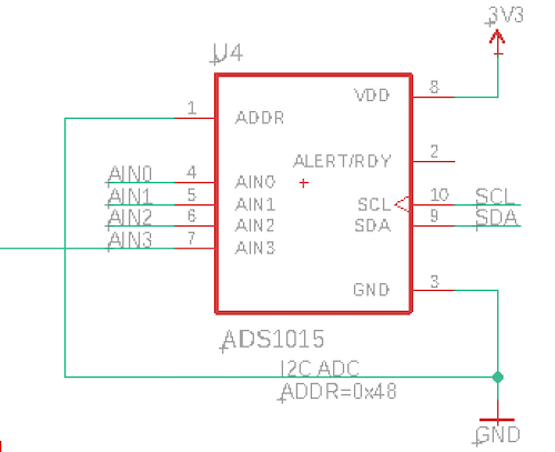
While pin A3 on the M8 connector is available for ADC use, this design includes a ADS1015 I2C ADC to allow for additional analog-to-digital input channels.
While this design runs the ADC at 3.3V, it can be used with the technique in the AN013 Tracker GPIO application note use an I2C level shifter and run the ADC at 5V, allowing full 5V analog inputs.
AIN0, AIN1, and AIN2 are available on the expansion connector. AIN3 is connected to the tank level sensor.
You can have up to 4 ADS1015 on the I2C bus, just in case you need 16 analog inputs!
Also you can use AIN0 and AIN1 together as a differential input. AIN2 can only be used single-ended since AIN3 is used internally.
One caveat: The ADS1015 does not measure edge-to-edge at 12-bit. You can adjust the settings but to measure a full 0 - 3.3V single-ended signal (PGA1 mode) results in a range of 0 - 1562, rather than 0 - 4095. It's a bit more than 10-bit ADC, essentially.
12V boost converter
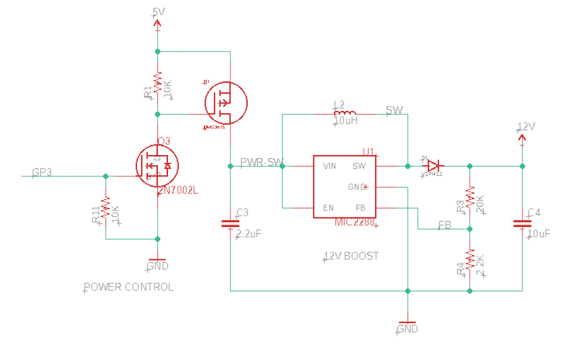
This shows how you can power low-current 12V sensors, like the tank level sensor. Keep in mind that there's a small LiPo battery in the Tracker One, and a 370 mA 3.6 to 5V boost converter for CAN_5V inside the Tracker One. Boosting it again to 12V is not particularly efficient, but works fine for this sensor. The boost converter is controlled by a MCP23008 GPIO. It's normally powered down but you can turn it on right before you capture a sample and turn it off again to conserve power.
Q1 is a P-channel MOSFET high-side switch that can supplies the power to the boost converter. Since the gate requires a pull-up to 5V (so it will default to off) it can't be directly connected to the 3.3V GPIO on the MCP23008 GPIO expander. Pulling the gate low turns on the MOSFET and the boost converter.
Q3 is an N-channel MOSFET (2N7002) low-side switch. The gate is connected to GPIO3 on the MCP23008. Setting to gate high (3.3V) turns on Q3, which pull down the gate on Q1, which turns on the boost converter.
U1 is the boost converter, a Microchip Technology MIC2288YD5-TR. It's tiny, inexpensive ($0.56) and only requires a few additional passive components. It converts the 5V CAN_5V to 12V.
Tank level sensor circuit
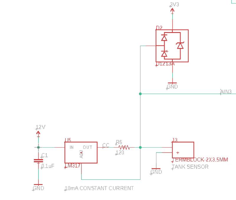
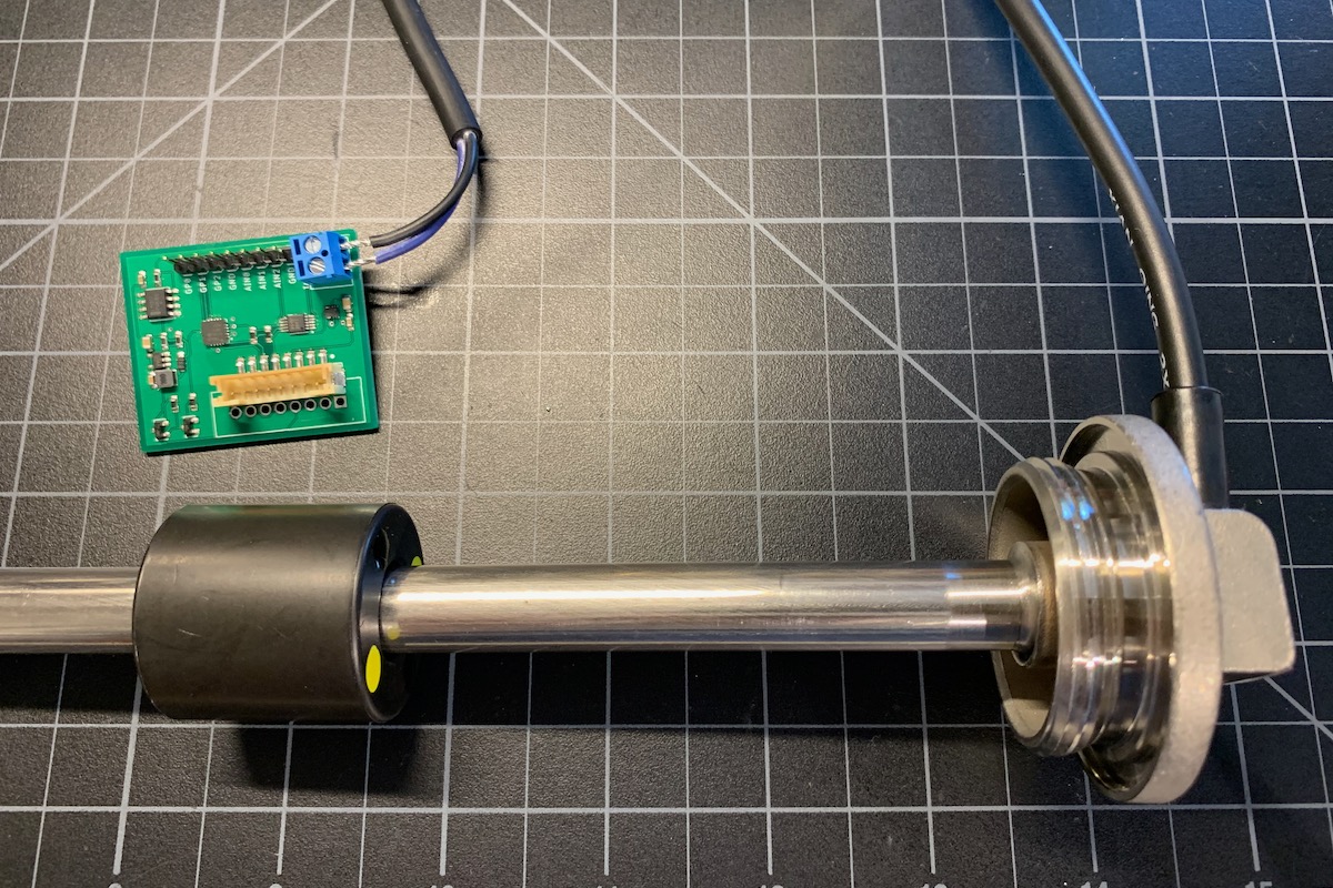
At least in the United States, it's common for fuel tank level sensors to be 240 - 33 ohm variable resistance. This sensor is the one in the picture, which I got mainly because it's short enough to not be unwieldy sitting on my desk.
As the 33 ohm resistance is too small to set up a traditional voltage divider, this circuit instead uses a LM317 constant current supply.
The current is configured by the resistor, and at 120 ohms, the current is 10.42 mA. The LM317 will either have no current (open connection), or will have 10.42 mA regardless of load. You can short it to ground and the current will still be limited to 10.42 mA.
We use this to our advantage with the 240 - 33 ohm sensor and measure the voltage drop across this resistance since the current is constant.
Using Ohm's Law, V=IR, at 240 ohms (tank empty) the voltage drop is 240Ω × 0.01042A = 2.5V. Expected value is 1183, and the measured value with the sensor above was 1261, which is reasonable.
At 33 ohms (tank full) the voltage drop is 33Ω × 0.01042A = 0.34V. Expected ADC value around 161. Actual value with the sensor above is 256.
When the sensor is disconnected there is no current, so that's fine, however if there is an incorrect resistance above 240 ohms, the voltage at the ADC can exceed the limit. The D1213A (D2) Zener diode + rail-to-rail diodes protects the ADC from excess voltage in this case. It's also a TVS to protect the ADC from surge voltages on the sensor or sensor cable.
The reason the 12V supply is necessary is that the LM317 only works at 5V + load voltage, thus the minimum is 8.3V. 12V is reasonable choice since it may also be useful for other sensors that actually require 12V.
BoM (Bill of Materials)
| Quantity | Part | Description | Example | Cost |
|---|---|---|---|---|
| 1 | C1 | Capacitor Ceramic 0.1uF 0603 | Panasonic GRM188R71C104KA01D | |
| 1 | C3 | CAP CER 2.2UF 25V X5R 0603 | Murata GRM188R61E225KA12D | |
| 2 | C4, C6 | Capacitor Ceramic 10uF 16V 0805 | Murata GRM21BR61C106KE15L | |
| 1 | C5 | Capacitor Ceramic 4.7uF 6.3V 0603 | Murata GRM188R60J475KE19J | |
| 4 | R1, R2, R5, R11 | Resistor 10K 5% 1/4W 0603 | Panasonic ERJ-PA3J103V | |
| 1 | R3 | RES SMD 20K OHM 1% 1/10W 0603 | Panasonic ERJ-3EKF2002V | |
| 1 | R4 | RES SMD 2.2K OHM 1% 1/10W 0603 | Panasonic ERJ-3EKF2201V | |
| 1 | R6 | RES SMD 120 OHM 1% 1/10W 0603 | Panasonic ERJ-3EKF1200V | |
| 1 | D1 | Diode Schottky 120V 2A | Vishay V2PM12HM3/H | $0.35 |
| 1 | D2 | TVS DIODE 3.3V 10V 1A SOT-23 | Diodes Inc D1213A-02SOL-7 | $0.40 |
| 1 | L2 | FIXED IND 10UH 1A 276 MOHM SMD | Bourns SRN3015-100M | $ 0.46 |
| 1 | Q1 | MOSFET P-CHAN 24V SOT23 | Diodes Inc DMP2045U-7 | $0.43 |
| 1 | Q3 | MOSFET N-CHAN SOT23 | On Semiconductor 2N7002LT1G | $0.16 |
| 1 | U1 | IC REG BOOST ADJ 1.2A TSOT23-5 | Microchip MIC2288YD5-TR | $0.56 |
| 1 | U2 | XCL224 3.3V regulator | Torex XCL224A333D2-G | $ 2.43 |
| 1 | U3 | IC I/O EXPANDER I2C 8B 20-QFN | Microchip MCP23008T-E/ML | $1.10 |
| 1 | U4 | IC ADC 4-ch 12-bit I2C 10-VSSOP | TI ADS1015IDGSR | $2.68 |
| 1 | J1 | TERMBLOCK-2X3.5MM | On Shore OSTTE020161 | $0.67 |
| Male header pins 0.1" | Sullins PRPC040SAAN-RC |
Choose one of:
| Quantity | Part | Description | Example | Cost |
|---|---|---|---|---|
| 1 | J3 | Conn SMD 8 position 2.00mm | JST B8B-PH-SM4-TB(LF)(SN) | $1.00 |
| J7 | Male Header Pins (8x0.1") | Sullins PRPC040SAAN-RC | ||
| 1 | J7 | Screw Terminal Block 8x0.1" PTH | On Shore OSTVN08A150 | $2.36 |
Firmware
Getting the Tracker Edge firmware
You can download a complete project for use with Particle Workbench as a zip file here:
Version:
- Extract tracker-an018.zip in your Downloads directory
- Open the tracker-an018 folder in Workbench using File - Open...; it is a pre-configured project directory.
- From the Command Palette (Command-Shift-P or Ctrl-Shift-P), use Particle: Configure Project for Device.
- If you are building in the cloud, you can use Particle: Cloud Flash or Particle: Cloud Compile.
- If you are building locally, open a CLI window using Particle: Launch CLI then:
particle library copy
Manually
The Tracker Edge firmware can be downloaded from GitHub:
https://github.com/particle-iot/tracker-edge
You will probably want to use the command line as there are additional commands you need to run after cloning the source:
git clone https://github.com/particle-iot/tracker-edge
cd tracker-edge
git submodule update --init --recursive
- Open Particle Workbench.
- From the command palette, Particle: Import Project.
- Run Particle: Configure Workspace for Device, select version 1.5.4-rc.1, 2.0.0-rc.3, or later, Tracker, and your device.
- Run Particle: Flash application (local).
Make sure you've used the Mark As Development Device option for your Tracker device in your Tracker product. If you don't mark the device as a development device it will be flashed with the default or locked product firmware version immediately after connecting to the cloud, overwriting the application you just flashed.
Add the libraries
From the command palette in Workbench, Particle: Install Library then enter SparkFun_ADS1015_Arduino_Library. Repeat for MCP23008-RK.
If you prefer to edit project.properties directly, add these:
The source
Digging in
MCP23008 gpio(Wire3, 0x20);
ADS1015 adc;
We need to initialize global objects for the GPIO expander and ADC. The ADS1015 gets the I2C port and address in the begin() function.
Tracker::instance().location.regLocGenCallback(myLocationGenerationCallback);
Since we add the level to location events, we need to register a callback.
pinMode(CAN_PWR, OUTPUT);
digitalWrite(CAN_PWR, HIGH);
It's necessary to turn on CAN_PWR to enable CAN_5V on the M8 connector.
gpio.begin();

gpio.pinMode(0, OUTPUT);
gpio.digitalWrite(0, HIGH);

gpio.pinMode(LEVEL_PIN, OUTPUT);
gpio.digitalWrite(LEVEL_PIN, HIGH);
Initialize the GPIO expander. If you are using the expansion connector, GPIO0, GPIO1, and GPIO2 are exposed on the connection and should be configured here.
GPIO3 (LEVEL_PIN) is used for turning on and off the 12V boost converter.
bool bResult = adc.begin(ADS1015_ADDRESS_GND, Wire3);
if (!bResult) {
    Log.error("ADC initialization failed");
}

// Set gain to PGA1: FSR = +/-4.096V
// This parameter expresses the full-scale range of the ADC scaling.
// Do not apply more than VDD + 0.3 V to the analog inputs of the device.
// (This means 3.3V will be approximately 1652)
adc.setGain(ADS1015_CONFIG_PGA_1);
Sets the ADC parameters.
int readLevel() {
    // Turn on boost converter
    gpio.digitalWrite(LEVEL_PIN, HIGH);

    delay(10);

    int16_t level = adc.getSingleEnded(3);

    gpio.digitalWrite(LEVEL_PIN, LOW);

    return (int) level;
}
This is how we read the level sensor. Turn on the boost converter, wait a moment for it to settle, read the ADC value, then turn off the boost converter.
void myLocationGenerationCallback(JSONWriter &writer, LocationPoint &point, const void *context)
{
    writer.name("level").value(readLevel());
}
Adds the tank level to the location events. It would probably be a good idea to transform it into some more useful value like gallons or liters, but that's left out here since it's dependent on the size and shape of the tank.
If you're using AIN0 - AIN3 on the expansion connector, you might want to store the values in the location event.
writer.name("ain0").value(adc.getSingleEnded(0));
writer.name("ain1").value(adc.getSingleEnded(1));
writer.name("ain2").value(adc.getSingleEnded(2));