Tracker prototype to board
You can download the files associated with this app note as a zip file.
This application note demonstrates how start prototyping with off-the-shelf I2C sensors and the Tracker SoM Evaluation Board and migrate to using a custom board for the Tracker One M8 Connector. While this specific example is for a thermocouple sensor, the techniques can be used with any sensor.
Prototype version
One of the best ways to expand the Tracker One is using I2C, since that interface makes it possible to add multiple external peripherals off the single M8 connector. You can use the same techniques on the Tracker SoM Evaluation Board and Tracker SoM.
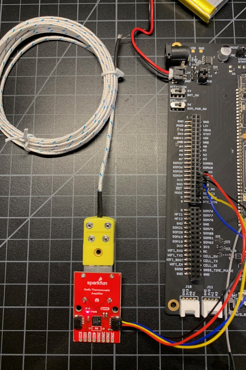
For this example we'll add thermocouple sensor and add the temperature to location publishes using the Tracker SoM Evaluation Board.
We'll also use the SparkFun Qwiic line of products for easy prototyping. In the second part of this tutorial we'll make our own thermocouple adapter board instead of using the Qwiic board.
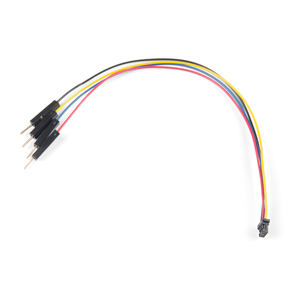
With the Evaluation board you'll need the Qwiic connector to prototyping wires or the cable assortment that includes it.
And you'll need the thermocouple adapter. I used a SparkFun Qwiic Thermocouple Amplifier - MCP9600 (PCC Connector) but the one with screw terminals also works. Just make sure it's one of the MCP9600 versions.
If using the one with the PCC connector, you can get the thermocouple from SparkFun or this one from Amazon but be careful because there are two sizes of K-type thermocouple connectors and the PCC connector is often referred to as the "mini" connector.
Connect the following wires to the Tracker SoM Evaluation Board expansion connector:
| Color | Pin | Purpose |
|---|---|---|
| Blue | MCU_RX | SDA (I2C data) |
| Yellow | MCU_TX | SCL (I2C clock) |
| Red | 3V3 | Power 3.3V |
| Black | GND | Ground |
Instead of using D0/D1 for I2C like on other Particle devices, in this case we'll be using the multi-function port pins MCU_RX and MCU_TX instead. On the Tracker SoM the TX and RX pins can be reconfigured to be Wire3 instead of Serial1, allowing a single set of pins to be GPIO, serial, or I2C on the M8 connector.
Note: All GPIO, ADC, and peripherals such as I2C, Serial, and SPI are 3.3V maximum and are not 5V tolerant. You must never use pull-ups to 5V on the I2C interface!
Device firmware
Getting the Tracker Edge firmware
You can download a complete project for use with Particle Workbench as a zip file here:
Version:
- Extract tracker-an019.zip in your Downloads directory
- Open the tracker-an019 folder in Workbench using File - Open...; it is a pre-configured project directory.
- From the Command Palette (Command-Shift-P or Ctrl-Shift-P), use Particle: Configure Project for Device.
- If you are building in the cloud, you can use Particle: Cloud Flash or Particle: Cloud Compile.
- If you are building locally, open a CLI window using Particle: Launch CLI then:
particle library copy
Manually
The Tracker Edge firmware can be downloaded from GitHub:
https://github.com/particle-iot/tracker-edge
You will probably want to use the command line as there are additional commands you need to run after cloning the source:
git clone https://github.com/particle-iot/tracker-edge
cd tracker-edge
git submodule update --init --recursive
- Open Particle Workbench.
- From the command palette, Particle: Import Project.
- Run Particle: Configure Workspace for Device, select version 1.5.4-rc.1, 2.0.0-rc.3, or later, Tracker, and your device.
- Run Particle: Flash application (local).
Make sure you've used the Mark As Development Device option for your Tracker device in your Tracker product. If you don't mark the device as a development device it will be flashed with the default or locked product firmware version immediately after connecting to the cloud, overwriting the application you just flashed.
Add the libraries
From the command palette in Workbench, Particle: Install Library then enter SparkFun_MCP9600_Arduino_Library.
If you prefer to edit project.properties directly, add:
The source
This is the modified main.cpp to implement thermocouple support:
Digging in
#include "SparkFun_MCP9600.h"

MCP9600 tempSensor;
We need to include the library header file and a global variable for the sensor library object.
// Turn on CAN power (needed when using M8 connector only)
pinMode(CAN_PWR, OUTPUT);
digitalWrite(CAN_PWR, HIGH);
At this point, we don't need to turn on CAN_PWR since we're using the built-in 3.3V regulator on the Tracker SoM evaluation board, but this code will also be used for our custom board which will require it.
// Set the multi-function pins for use the I2C instead of serial or GPIO
Wire3.begin();
Wire3.setClock(100000);

// Initialize the MCP9600 I2C thermocouple library
tempSensor.begin(0x60, Wire3);
This sets the multi-function pins to I2C mode and initializes the library. The constant 0x60 is the I2C address of the sensor. Note the use of Wire3 instead of just Wire. On the Tracker SoM this uses the multifunction pins for I2C instead of D0 and D1. While you can use D0 and D1 for I2C on the Tracker SoM and Tracker SoM evaluation board, you cannot on the Tracker One as pins D0 and D1 are not available and not exposed on the M8 connector.
void myLocationGenerationCallback(JSONWriter &writer,
    LocationPoint &point, const void *context)
{
    if (tempSensor.available()) {
        // Add "thermocouple" with a value of degrees C to the location publish event
        // This shows up in the Custom Data section of the device details
        writer.name("thermocouple").value(tempSensor.getThermocoupleTemp(), 2); // degrees C
    }
    else {
        Log.info("no sensor");
    }
}
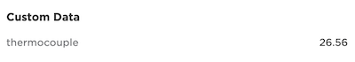
This adds the thermocouple temperature data to the location publishes. If you check the device details it should show up as custom data:
Expanding the Tracker One
Using the M8 connector
The M8 (8mm) 8-pin connector is standard, however it's not common. Some other connectors like M12 are more common, however, the 12mm connector would have required a taller enclosure to fit the larger connector. To simplify designs, Particle will provide a M8 female-to-wires cable, similar to this.
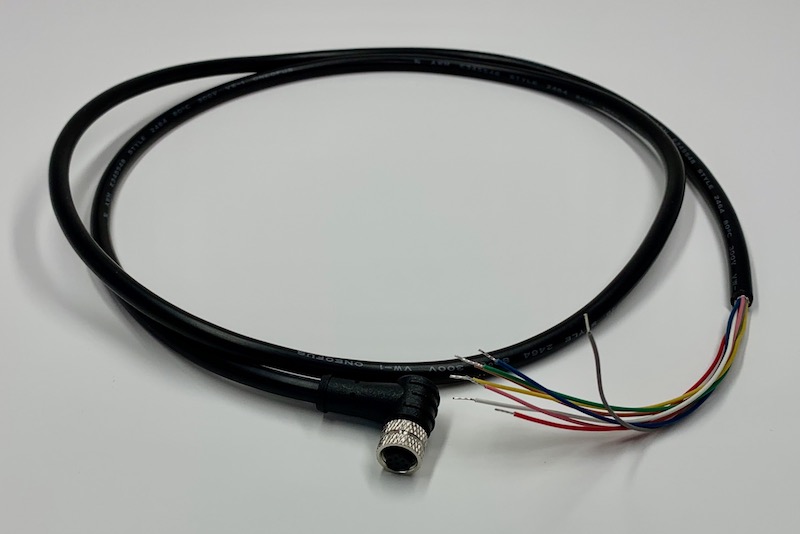
The common use case will be to include a cable gland in your expansion enclosure, pass the wires through the gland, and terminate them on your custom expansion board.
You'd typically connect those wires to your custom expansion board using one of several methods:
- Terminate with pins in a PHR-8 to mate with a B8B-PH on your expansion board
- Terminate with screw terminals on your board
- Terminate by soldering the wires to your board
With the Tracker One carrier board directly
Inside the Tracker One is the Carrier Board. It can be purchased separately in case you want to use the Tracker One features in your own enclosure. The design for the Tracker One enclosure is open-source and can be modified to fit your needs. The Carrier Board has a B8B-PH 8-pin connector on the board, and a short cable that attaches to the M8 8-pin IP67 connector mounted on the side of the enclosure.
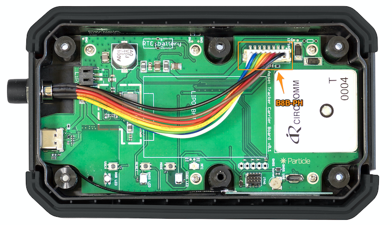
When expanding on the Tracker One Carrier Board, you may prefer to connect your expansion device to the B8B-PH connector on the board directly, especially if you are putting your expansion board in the enclosure with your Tracker One Carrier Board.
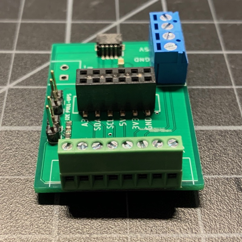
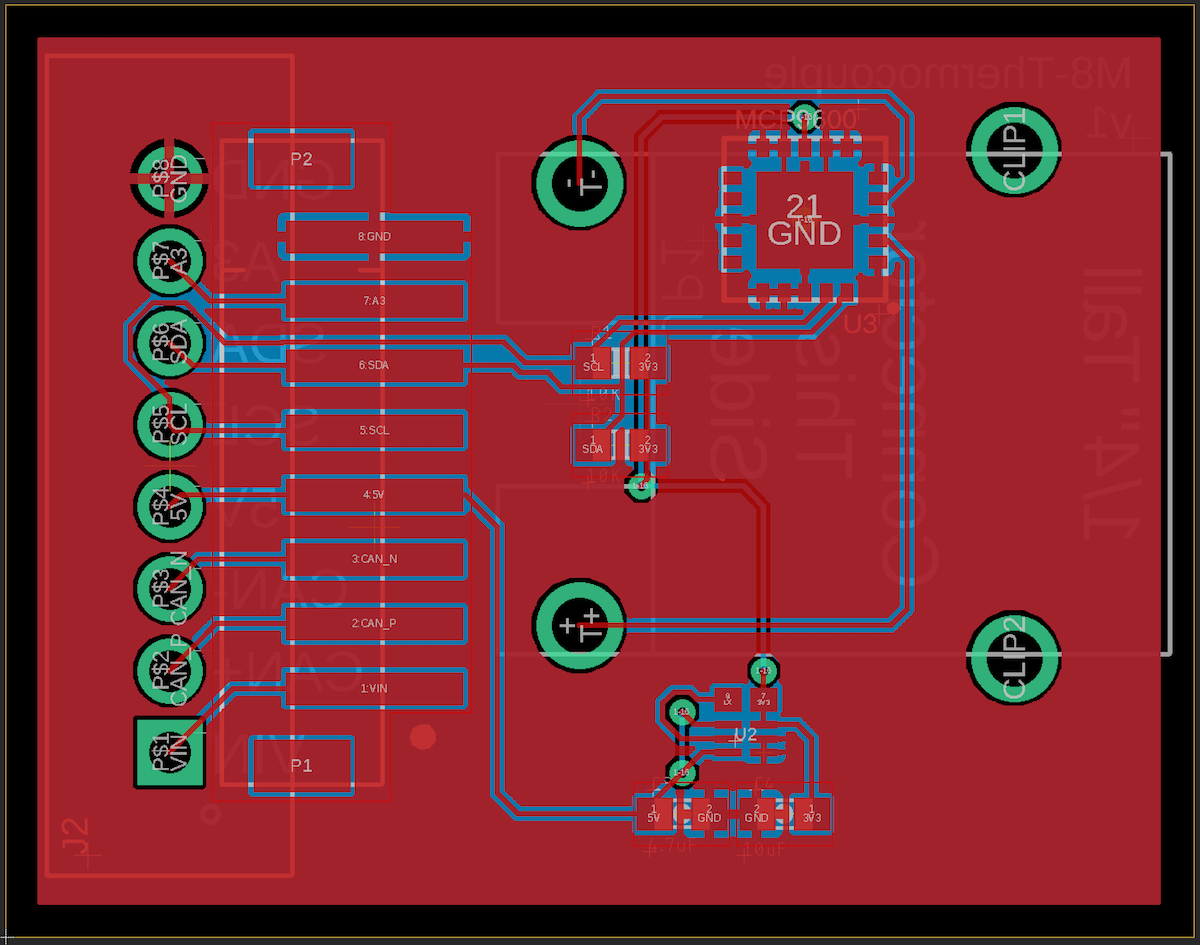
M8 Thermocouple adapter board
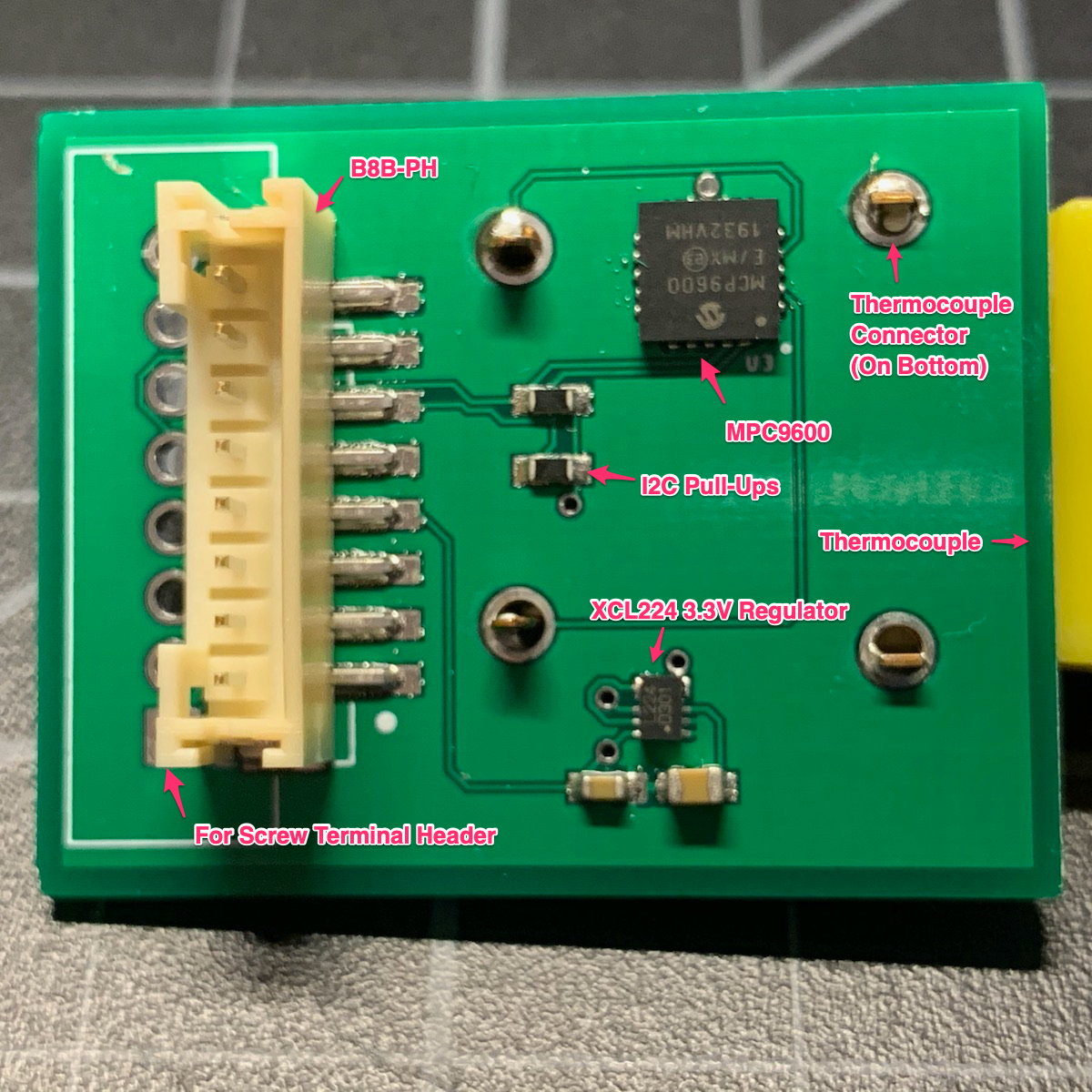
Here's the board that we will be building. This board can only be reflow soldered as both the XCL224 and the MCP9600 have bottom pads instead of exposed leads.
One advantage of starting with the SparkFun board is that Eagle CAD schematic and board files are available for all of their designs.
Schematic
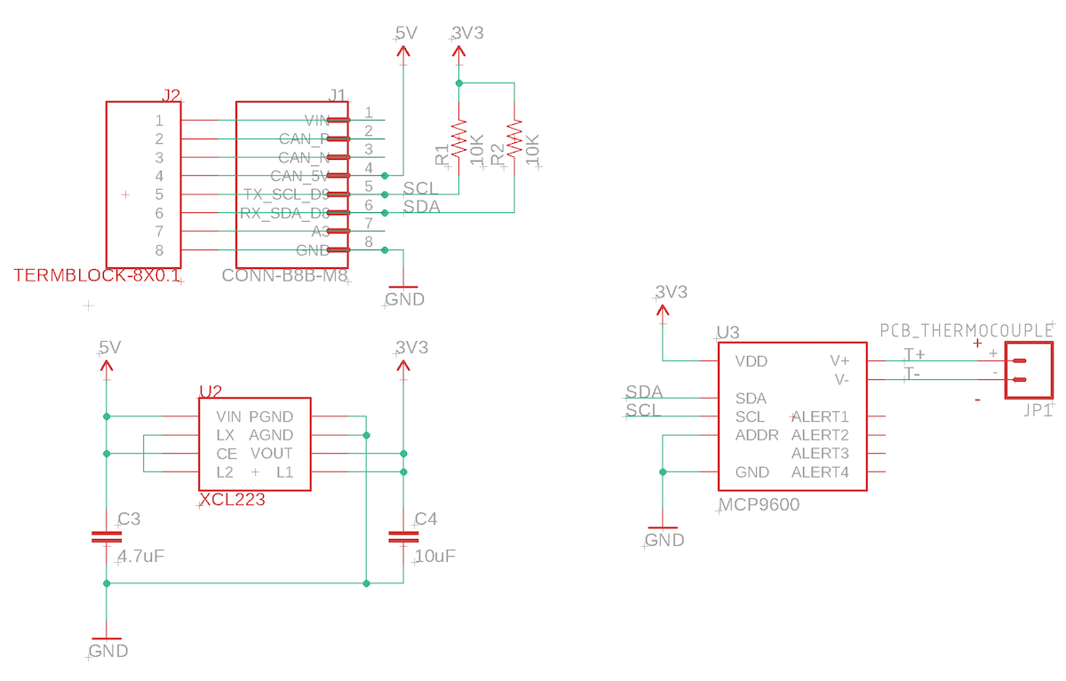
The schematic is really simple:
There is a spot for either a B8B-PH connector, screw terminals, male header pins, or soldered wires, whichever you prefer.
The I2C lines require pull-ups to 3V3.
The XCL223/XCL224 3.3V regulator converts the CAN_5V on the M8 connector to 3.3V as the nRF52840 logic is all 3.3V, as is the MCP9600. It requires two capacitors: a 4.7 uF input capacitor and a 10 uF output capacitor.
Finally the MCP9600 is the thermocouple interface. That's it!
Board layout
BoM (Bill of Materials)
| Quantity | Part | Description | Example | Cost |
|---|---|---|---|---|
| 1 | C3 | Capacitor Ceramic 4.7uF 6.3V 0603 | Murata GRM188R60J475KE19J | |
| 1 | C4 | Capacitor Ceramic 10uF 16V 0805 | Murata GRM21BR61C106KE15L | |
| 2 | R1, R2 | Resistor 10K 5% 1/4W 0603 | Panasonic ERJ-PA3J103V | |
| 1 | U2 | XCL224 3.3V regulator | Torex XCL224A333D2-G | $ 2.43 |
| 1 | U3 | IC THERMOCOUPLE TO I2C 20MQFN | Microchip MCP9600-E/MX | $6.96 |
| 1 | JP1 | PCC-SMP-K Connector | SparkFun 13612 | $3.95 |
Choose one of:
| Quantity | Part | Description | Example | Cost |
|---|---|---|---|---|
| 1 | J1 | Conn SMD 8 position 2.00mm | JST B8B-PH-SM4-TB(LF)(SN) | $1.00 |
| J2 | Male Header Pins (8x0.1") | Sullins PRPC040SAAN-RC | ||
| 1 | J2 | Screw Terminal Block 8x0.1" PTH | On Shore OSTVN08A150 | $2.36 |
Connecting to the Tracker One
PHR-8 to PHR-8
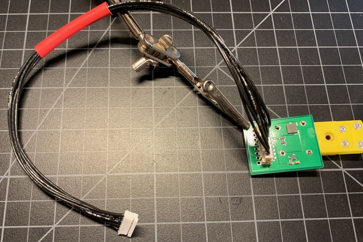
If you're using the Tracker Carrier Board and adding your sensor as a daughter board, you might want to use a PHR-8 to PHR-8 cable like this. This is a 12" long one for prototyping, but you can get the wires with pins already crimped at varying lengths.
M8 8-pin female to PHR-8
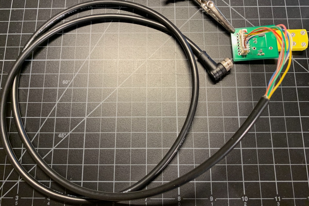
This option is handy during development. The PHR-8 connector is much easier to plug and unplug than the M8 or 8 screw terminals. It the M8 to flying leads cable shown above, but terminated with pins for the PHR-8.
Note: Do not follow the color code in the picture. That's an early version of the cable that used a different color code.
Screw terminals
Another option is to add screw terminals to your board. This makes it possible to use the M8 to flying-wires cable and terminate the cable at the screw terminals. This is a good option if you want your cable to pass through a gland.
This is a different board, but the screw terminals work in the same way on the board above.