
Tracker relay
You can download the files associated with this app note as a zip file.
This application note shows how you can use relays with the Tracker One M8 connector. It includes two designs:
- Quad Relay (4x 10A SPDT relays)
- Dual Latching Relay (2x 16A SPDT latching relays)
The designs are similar.
Connecting
The M8 (8mm) 8-pin connector on the Tracker One is standard, however it's not common. Some other connectors like M12 are more common, however, the 12mm connector would have required a taller enclosure to fit the larger connector. To simplify designs, Particle will provide a M8 female-to-wires cable, similar to this. This is for illustration only and the design may vary in the future.
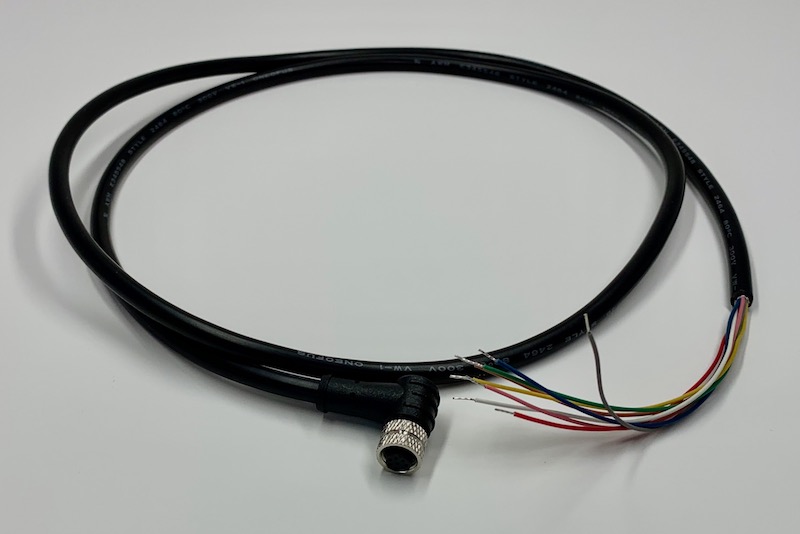
The common use case will be to include a cable gland in your expansion enclosure, pass the wires through the gland, and terminate them on your custom expansion board.
You'd typically connect those wires to your custom expansion board using one of several methods:
- Terminate with pins in a PHR-8 to mate with a B8B-PH on your expansion board
- Terminate with screw terminals on your board
- Terminate by soldering the wires to your board
This example can be used three different ways:
It can use the same B8B-PH connector that is inside the Tracker One on the Tracker Carrier board. This connector is inexpensive and can be attached directly to the Tracker One Carrier Board.
Or you can populate a 8x0.1" screw terminal header. This is good for connecting to the M8 to flying leads.
Or you can populate 0.1" male header pins, which are handy for use with male-to-female Dupont wires for connecting directly to the Tracker SoM evaluation board.
Common parts
This board is intended to be powered by the M8 connector, which includes the 5V CAN_PWR. This is a controllable boost power supply that supplies 5V at 370 mA even off battery.
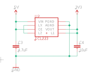
Since much of the logic including the nRF52840 GPIO and I2C run only at 3.3V, a 3.3V regulator (XCL224) is included in this design. This regulator is a tiny switching regulator and is nice because it does not require an external inductor, saving space and cost.
The XCL224 is a tiny and does not require an external inductor. It only requires 4.7 uF input and 10 uF output capacitors.
By using the I2C interface on the M8 connector you can easily add additional ports to your expansion device.
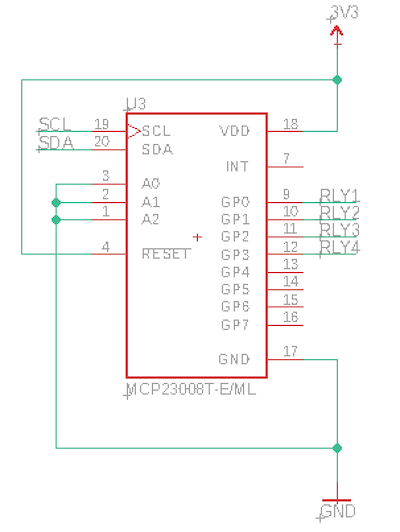
This design includes a Microchip MCP23008T-E/ML in a tiny 20-QFN-EP package. The AN013 Tracker GPIO example uses the much larger (but easier to solder) 18-SOIC package. The software is the same for both chip packages. The MCP23008 adds 8 GPIO pins via the I2C interface. This design uses it at 3.3V. The pins can be used as input, input pull-up, or output modes.
Only 4 of the 8 GPIO are used in this project, however since the MCP23008T-E/ML is so small an inexpensive it's not really worthwhile to source a separate 4-port GPIO expander.
Quad relay
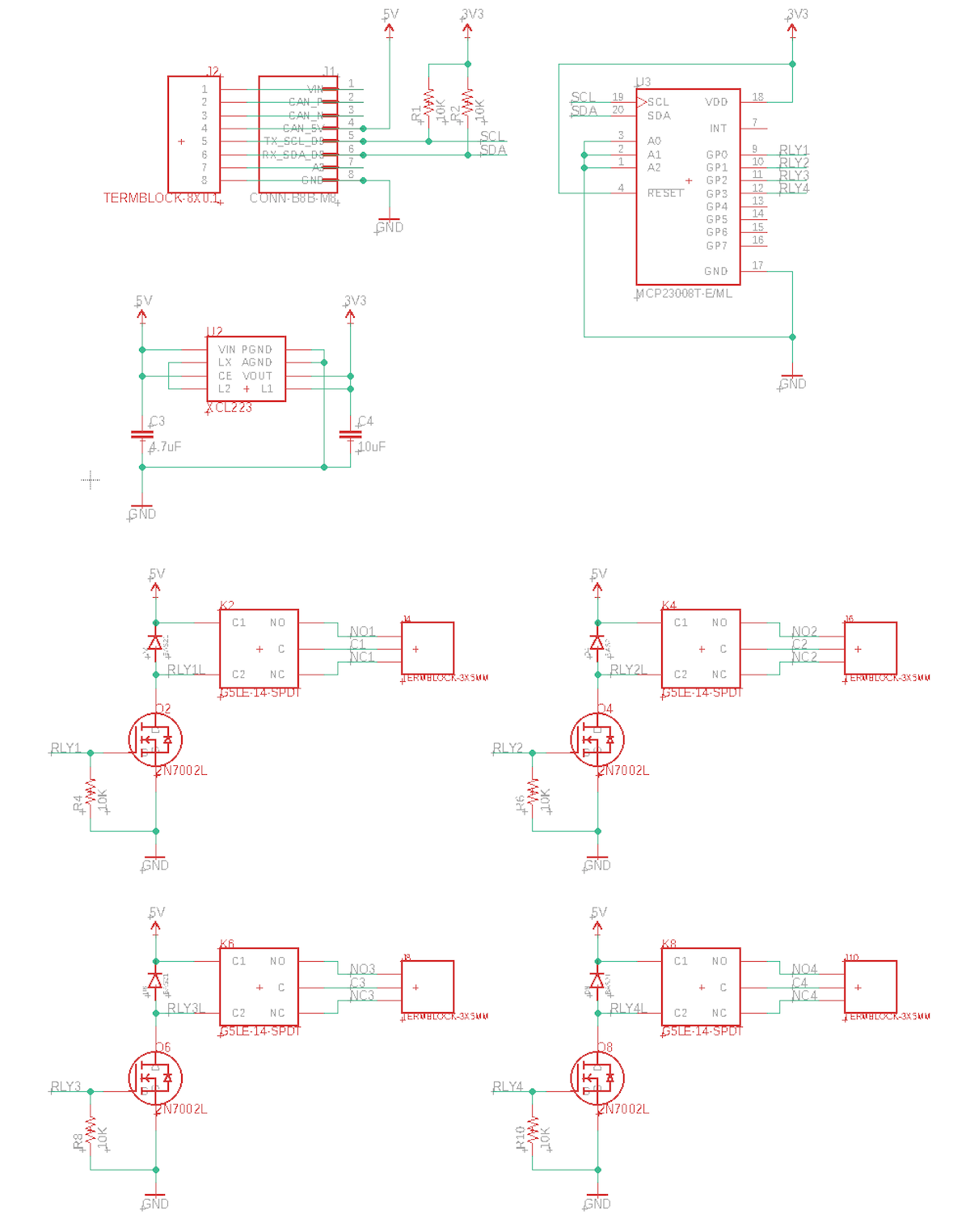
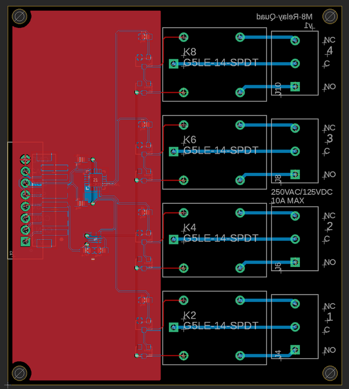
Schematic and board - quad relay
BoM (Bill of Materials) - quad relay
| Quantity | Part | Description | Example | Cost |
|---|---|---|---|---|
| 1 | C3 | Capacitor Ceramic 10uF 16V 0805 | Murata GRM21BR61C106KE15L | |
| 1 | C4 | Capacitor Ceramic 4.7uF 6.3V 0603 | Murata GRM188R60J475KE19J | |
| 6 | R1, R2, R4, R6, R8, R10 | Resistor 10K 5% 1/4W 0603 | Panasonic ERJ-PA3J103V | |
| 4 | Q2, Q4, Q6, Q8 | MOSFET N-CHAN SOT23 | On Semiconductor 2N7002LT1G | $0.16 |
| 1 | U2 | XCL224 3.3V regulator | Torex XCL224A333D2-G | $ 2.43 |
| 1 | U3 | IC I/O EXPANDER I2C 8B 20-QFN | Microchip MCP23008T-E/ML | $1.10 |
| 4 | D2, D4, D6, D8 | DIODE GEN PURP 200V 200MA SOT23 | Diodes Inc BAS21-7-F | $0.14 |
| 4 | K2, K4, K6, K8 | RELAY GEN PURPOSE SPDT 10A 5V | Omron G5LE-14 DC5 | 1.48 |
| 4 | J4, J6, J8, J10 | TERM BLK 3POS SIDE ENTRY 5MM PCB | On Shore ED700/3 | $1.84 |
Choose one of:
| Quantity | Part | Description | Example | Cost |
|---|---|---|---|---|
| 1 | J3 | Conn SMD 8 position 2.00mm | JST B8B-PH-SM4-TB(LF)(SN) | $1.00 |
| J7 | Male Header Pins (8x0.1") | Sullins PRPC040SAAN-RC | ||
| 1 | J7 | Screw Terminal Block 8x0.1" PTH | On Shore OSTVN08A150 | $2.36 |
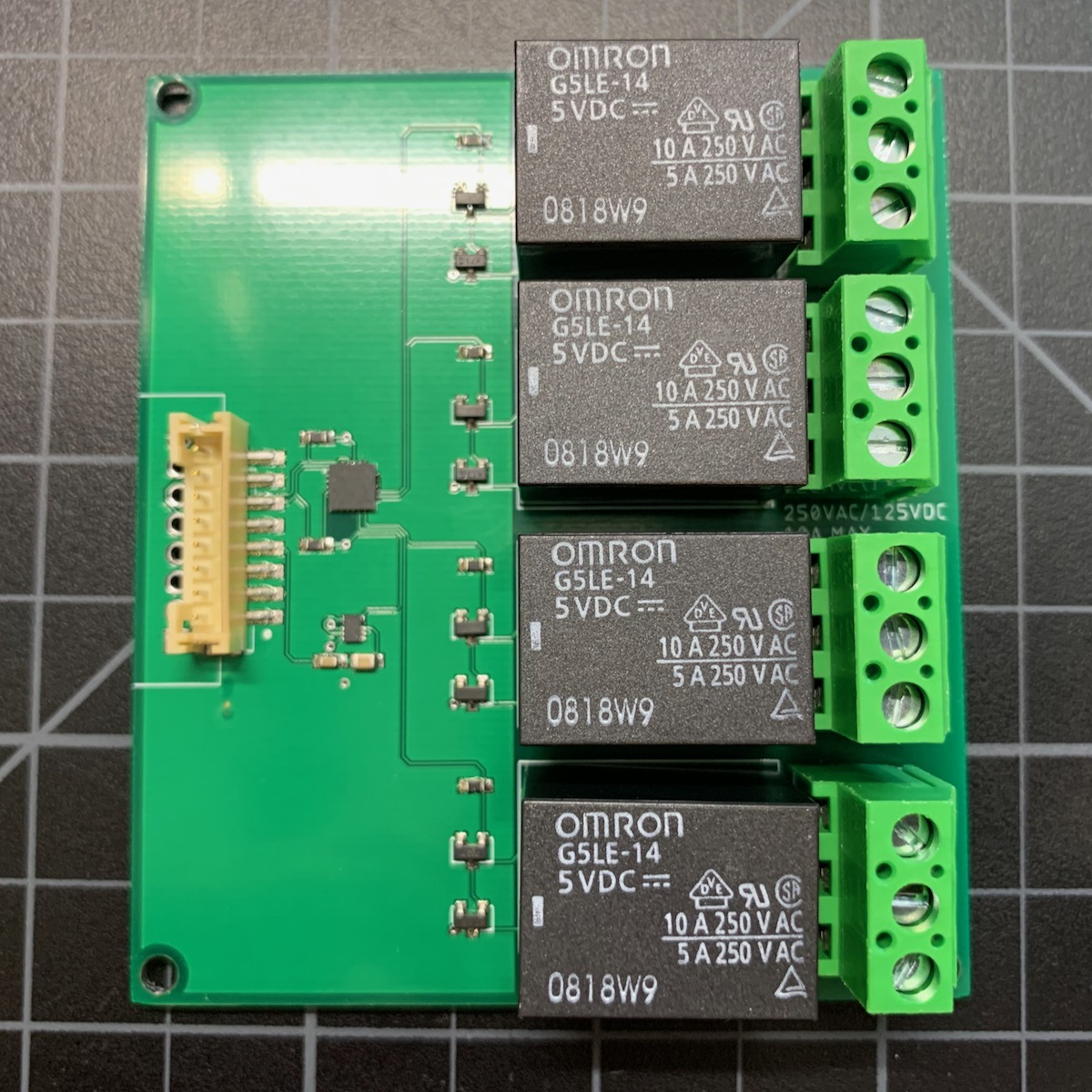
Design details - quad relay
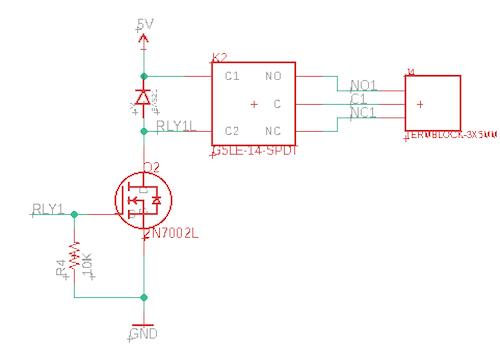
Each of the four relays has the same design. Some information on the relays:
- Omron Electronics Inc-EMC Div G5LE-14 DC5 ($1.48 each)
- General Purpose Relay SPDT (1 Form C) 5VDC Coil Through Hole
- 250VAC, 125VDC 10A - Max
- 79.4 mA coil current, non-latching
- Operate: 10 ms, Release: 5 ms
- 4 of these is 320 mA with all energized, the maximum reasonable on the 370 mA boost.
The 5V coil was selected because 3.3V relays are not generally available for relays larger than signal relays, and tend to be expensive. Since 5V is available from CAN_5V it's an obvious choice. (12V is a better choice if you happen to have 12V available.)
These relays have a high coil current (79.4 mA) so a transistor driver is required. This design uses a 2N7002 N-Channel MOSFET. The signal is pulled low by the 10K resistor, and driving the gate high by the MCP23008 GPIO will energize the relay.
Finally, the BAS21 diode is a flyback diode to prevent current from the relay coil from damaging the driver circuit. Any time you have a bare relay that doesn't internally include one, you must add one.
Firmware - quad relay
Getting the Tracker Edge firmware - quad relay
You can download a complete project for use with Particle Workbench as a zip file here:
Version:
- Extract tracker-an024-quad.zip in your Downloads directory
- Open the tracker-an024-quad folder in Workbench using File - Open...; it is a pre-configured project directory.
- From the Command Palette (Command-Shift-P or Ctrl-Shift-P), use Particle: Configure Project for Device.
- If you are building in the cloud, you can use Particle: Cloud Flash or Particle: Cloud Compile.
- If you are building locally, open a CLI window using Particle: Launch CLI then:
particle library copy
Manually
The Tracker Edge firmware can be downloaded from GitHub:
https://github.com/particle-iot/tracker-edge
You will probably want to use the command line as there are additional commands you need to run after cloning the source:
git clone https://github.com/particle-iot/tracker-edge
cd tracker-edge
git checkout origin/release/v8
git submodule update --init --recursive
- Open Particle Workbench.
- From the command palette, Particle: Import Project.
- Run Particle: Configure Workspace for Device, select version 1.5.4-rc.1, 2.0.0-rc.3, or later, Tracker, and your device.
- Run Particle: Flash application (local).
Add the libraries - quad relay
From the command palette in Workbench, Particle: Install Library then enter M8RelayRK.
If you prefer to edit project.properties directly, add this:
The source - quad relay
Testing - quad relay
This code adds a Particle function than can be controlled by the Particle CLI, console, mobile apps, etc..
Note: The call and library take a 0-based relay index (0 - 3), but the board is labeled 1 - 4.
| Command | Purpose |
|---|---|
particle call myTracker relay 0,1 |
Turn relay 1 on (NO contacts closed) |
particle call myTracker relay 0,0 |
Turn relay 1 off (NC contacts closed) |
particle call myTracker relay 1,1 |
Turn relay 2 on (NO contacts closed) |
particle call myTracker relay 1,0 |
Turn relay 2 off (NC contacts closed) |
particle call myTracker relay 2,1 |
Turn relay 3 on (NO contacts closed) |
particle call myTracker relay 2,0 |
Turn relay 3 off (NC contacts closed) |
particle call myTracker relay 3,1 |
Turn relay 4 on (NO contacts closed) |
particle call myTracker relay 3,0 |
Turn relay 4 off (NC contacts closed) |
Dual latching relay
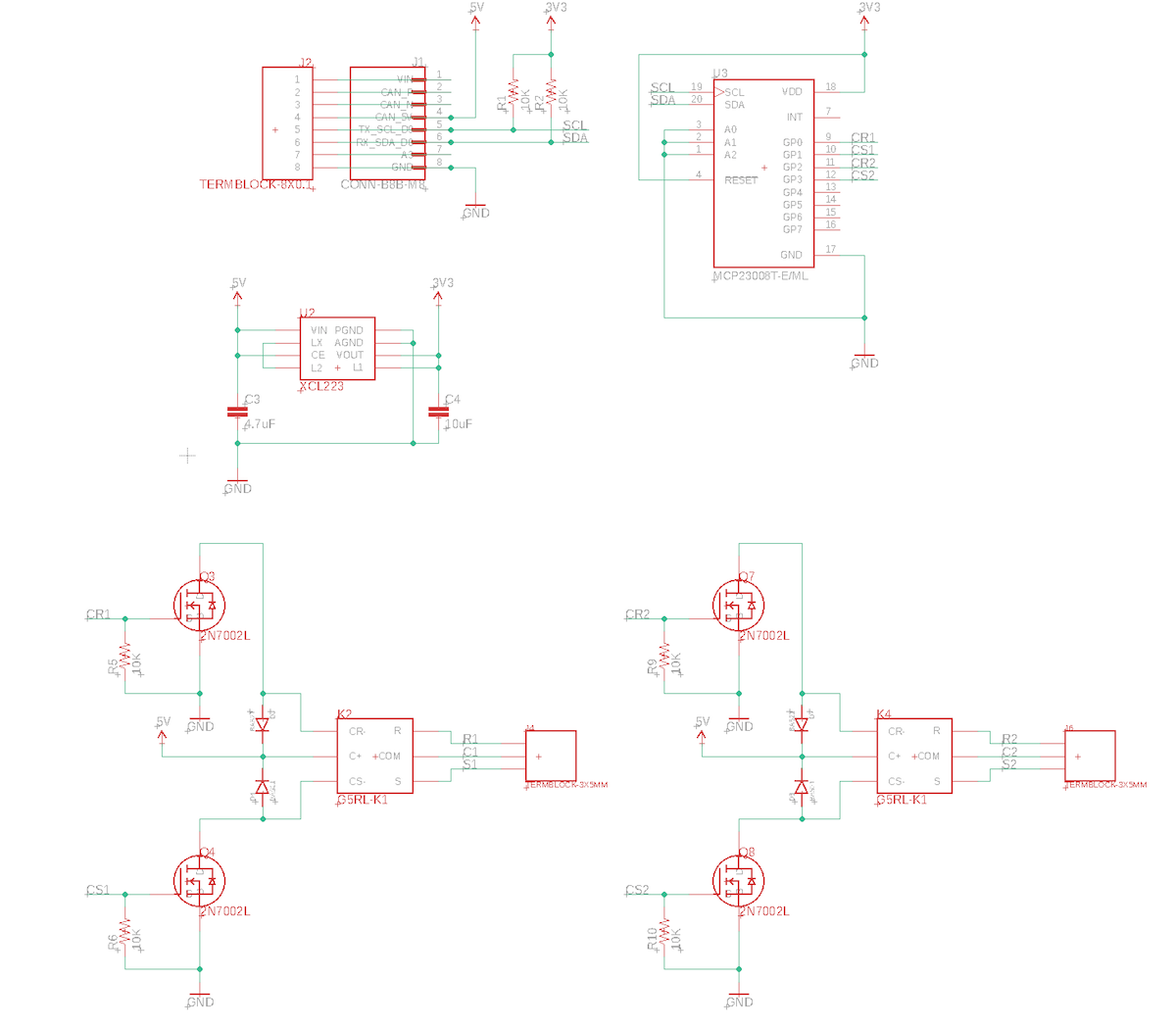
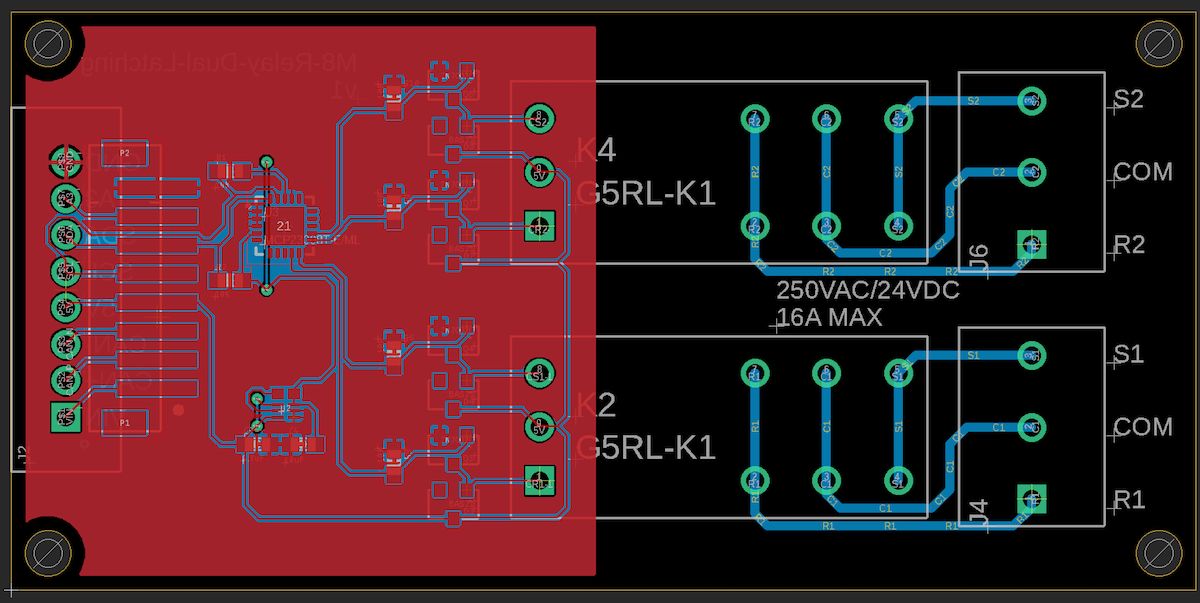
Schematic and board - dual latching relay
BoM (Bill of Materials) - dual latching relay
| Quantity | Part | Description | Example | Cost |
|---|---|---|---|---|
| 1 | C3 | Capacitor Ceramic 10uF 16V 0805 | Murata GRM21BR61C106KE15L | |
| 1 | C4 | Capacitor Ceramic 4.7uF 6.3V 0603 | Murata GRM188R60J475KE19J | |
| 6 | R1, R2, R4, R6, R8, R10 | Resistor 10K 5% 1/4W 0603 | Panasonic ERJ-PA3J103V | |
| 4 | Q3, Q4, Q7, Q8 | MOSFET N-CHAN SOT23 | On Semiconductor 2N7002LT1G | $0.16 |
| 1 | U2 | XCL224 3.3V regulator | Torex XCL224A333D2-G | $ 2.43 |
| 1 | U3 | IC I/O EXPANDER I2C 8B 20-QFN | Microchip MCP23008T-E/ML | $1.10 |
| 4 | D2, D4, D6, D8 | DIODE GEN PURP 200V 200MA SOT23 | Diodes Inc BAS21-7-F | $0.14 |
| 2 | K2, K4 | RELAY GEN PURPOSE SPDT 16A 5V LATCHING | Omron G5RL-K1-E-DC5 | $3.70 |
| 2 | J4, J6 | TERM BLK 3POS SIDE ENTRY 5MM PCB | On Shore ED700/3 | $1.84 |
Choose one of:
| Quantity | Part | Description | Example | Cost |
|---|---|---|---|---|
| 1 | J3 | Conn SMD 8 position 2.00mm | JST B8B-PH-SM4-TB(LF)(SN) | $1.00 |
| J7 | Male Header Pins (8x0.1") | Sullins PRPC040SAAN-RC | ||
| 1 | J7 | Screw Terminal Block 8x0.1" PTH | On Shore OSTVN08A150 | $2.36 |
Design details - dual latching relay
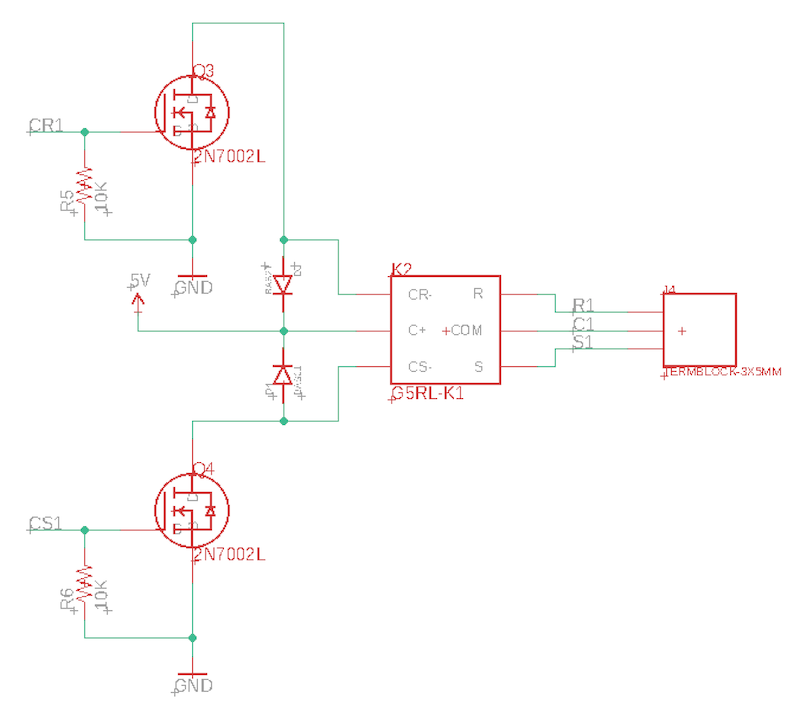
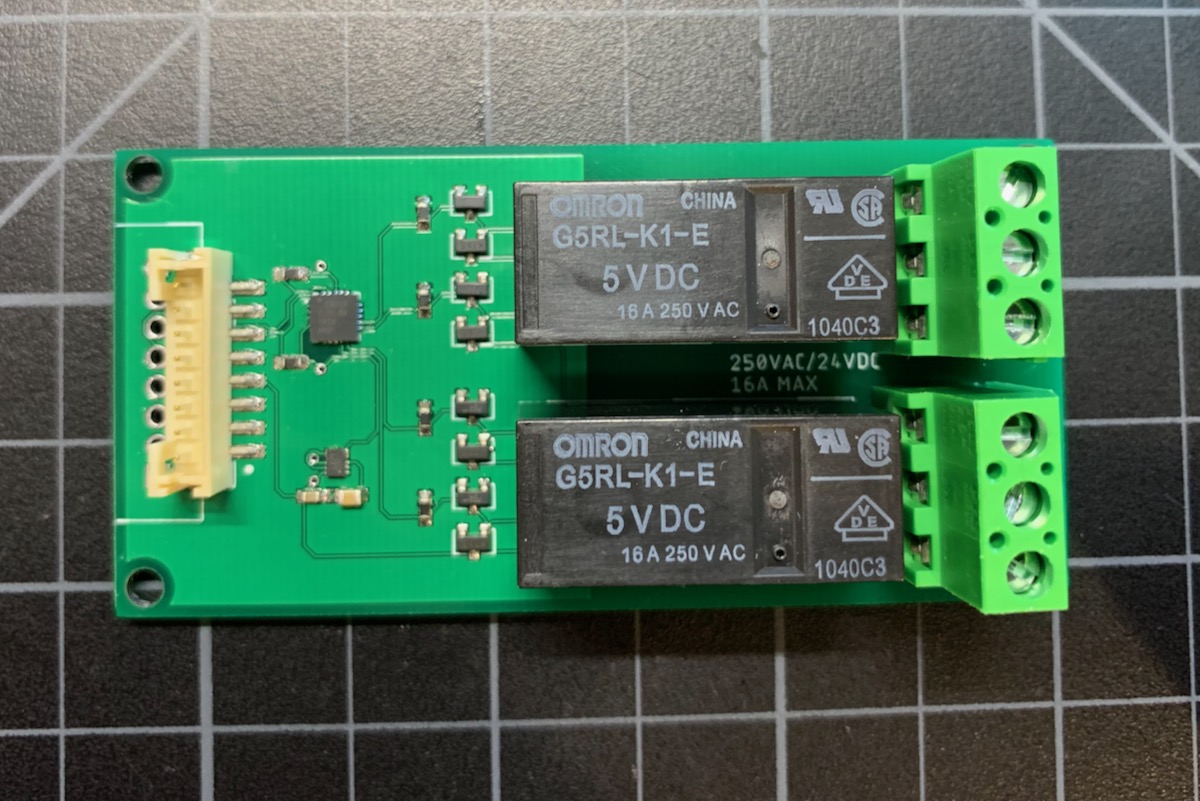
Each of the two relays has the same design. Some information on the relays:
- Omron Electronics Inc-EMC Div G5RL-K1-E-DC5 ($3.70 each)
- General Purpose Relay SPDT (1 Form C) 5VDC Coil Through Hole, Latching
- 250VAC, 24VDC 16A - Max
- 150 mA coil current
- Operate: 15 ms, Release: 15 ms
- Pulse to operate: 30 ms. minimum, 1 minute maximum.
The 5V coil was selected because 3.3V relays are not generally available for relays larger than signal relays, and tend to be expensive. Since 5V is available from CAN_5V it's an obvious choice. (12V is a better choice if you happen to have 12V available.)
These relays have a high coil current (150 mA) so a transistor driver is required. And latching relays have two separate coils, one for set and one for reset. This design uses a 2N7002 N-Channel MOSFET. The signal is pulled low by the 10K resistor, and driving the gate high by the MCP23008 GPIO will energize the relay. This is at the upper end of the current capability of the 2N7002 MOSFET, however the coil is only energized for 30 milliseconds since the relay is latching.
While energizing coils on both relays at the same time is possible within the power limit of CAN_5V, the software will only energize one at a time. Since it only takes 30 milliseconds, this should not be an issue.
Finally, the BAS21 diode is a flyback diode to prevent current from the relay coil from damaging the driver circuit. Any time you have a bare relay that doesn't internally include one, you must add one. And since the latching relay has two coils, there's one for each coil.
Firmware - dual latching relay
Getting the Tracker Edge firmware - dual latching relay
You can download a complete project for use with Particle Workbench as a zip file here:
Version:
- Extract tracker-an024-dual.zip in your Downloads directory
- Open the tracker-an024-dual folder in Workbench using File - Open...; it is a pre-configured project directory.
- From the Command Palette (Command-Shift-P or Ctrl-Shift-P), use Particle: Configure Project for Device.
- If you are building in the cloud, you can use Particle: Cloud Flash or Particle: Cloud Compile.
- If you are building locally, open a CLI window using Particle: Launch CLI then:
particle library copy
Manually
The Tracker Edge firmware can be downloaded from GitHub:
https://github.com/particle-iot/tracker-edge
You will probably want to use the command line as there are additional commands you need to run after cloning the source:
git clone https://github.com/particle-iot/tracker-edge
cd tracker-edge
git checkout origin/release/v8
git submodule update --init --recursive
- Open Particle Workbench.
- From the command palette, Particle: Import Project.
- Run Particle: Configure Workspace for Device, select version 1.5.4-rc.1, 2.0.0-rc.3, or later, Tracker, and your device.
- Run Particle: Flash application (local).
Make sure you've used the Mark As Development Device option for your Tracker device in your Tracker product. If you don't mark the device as a development device it will be flashed with the default or locked product firmware version immediately after connecting to the cloud, overwriting the application you just flashed.
Add the libraries - dual latching relay
From the command palette in Workbench, Particle: Install Library then enter M8RelayRK.
If you prefer to edit project.properties directly, add this:
The source - dual latching relay
Testing - dual latching relay
This code adds a Particle function than can be controlled by the Particle CLI, console, mobile apps, etc..
Note: The call and library take a 0-based relay index (0 - 1), but the board is labeled 1 - 2.
| Command | Purpose |
|---|---|
particle call myTracker relay 0,1 |
Set relay 1 (S1 to COM) |
particle call myTracker relay 0,0 |
Release relay 1 (R1 to COM) |
particle call myTracker relay 1,1 |
Set relay 2 (S2 to COM) |
particle call myTracker relay 1,0 |
Release relay 2 (R2 to COM) |