Tracker SHT3x temperature/humidity
You can download the files associated with this app note as a zip file.
Introduction
This application note illustrates several hardware and software techniques:
- Expanding the Tracker One using the M8 connector
- Interfacing with 5V I2C devices
- Connecting a SHT30 or SHT31 I2C Temperature and Humidity Sensor
- Adding custom data to your location publishes
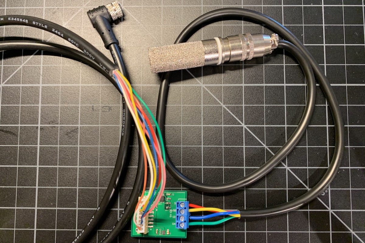
While the Tracker One board contains a precision thermistor, the sensor shown here is good for measuring temperature in locations separate from the Tracker, for example outside, in a refrigeration unit, etc..
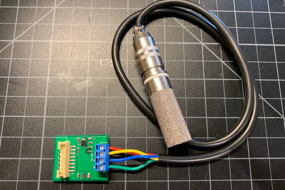
Instead of building your own board, you can also buy a pre-made M8 sensor cable. This cable includes the necessary voltage regulator inside the molded cable relief. While the software for both is the same, there is another tutorial available for the sensor cable as well.
Connecting
The M8 (8mm) 8-pin connector on the Tracker One is standard, however it's not common. Some other connectors like M12 are more common, however, the 12mm connector would have required a taller enclosure to fit the larger connector. To simplify designs, Particle will provide a M8 female-to-wires cable, similar to this. This is for illustration only and the design may vary in the future.
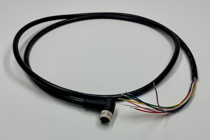
The common use case will be to include a cable gland in your expansion enclosure, pass the wires through the gland, and terminate them on your custom expansion board.
You'd typically connect those wires to your custom expansion board using one of several methods:
- Terminate with pins in a PHR-8 to mate with a B8B-PH on your expansion board
- Terminate with screw terminals on your board
- Terminate by soldering the wires to your board
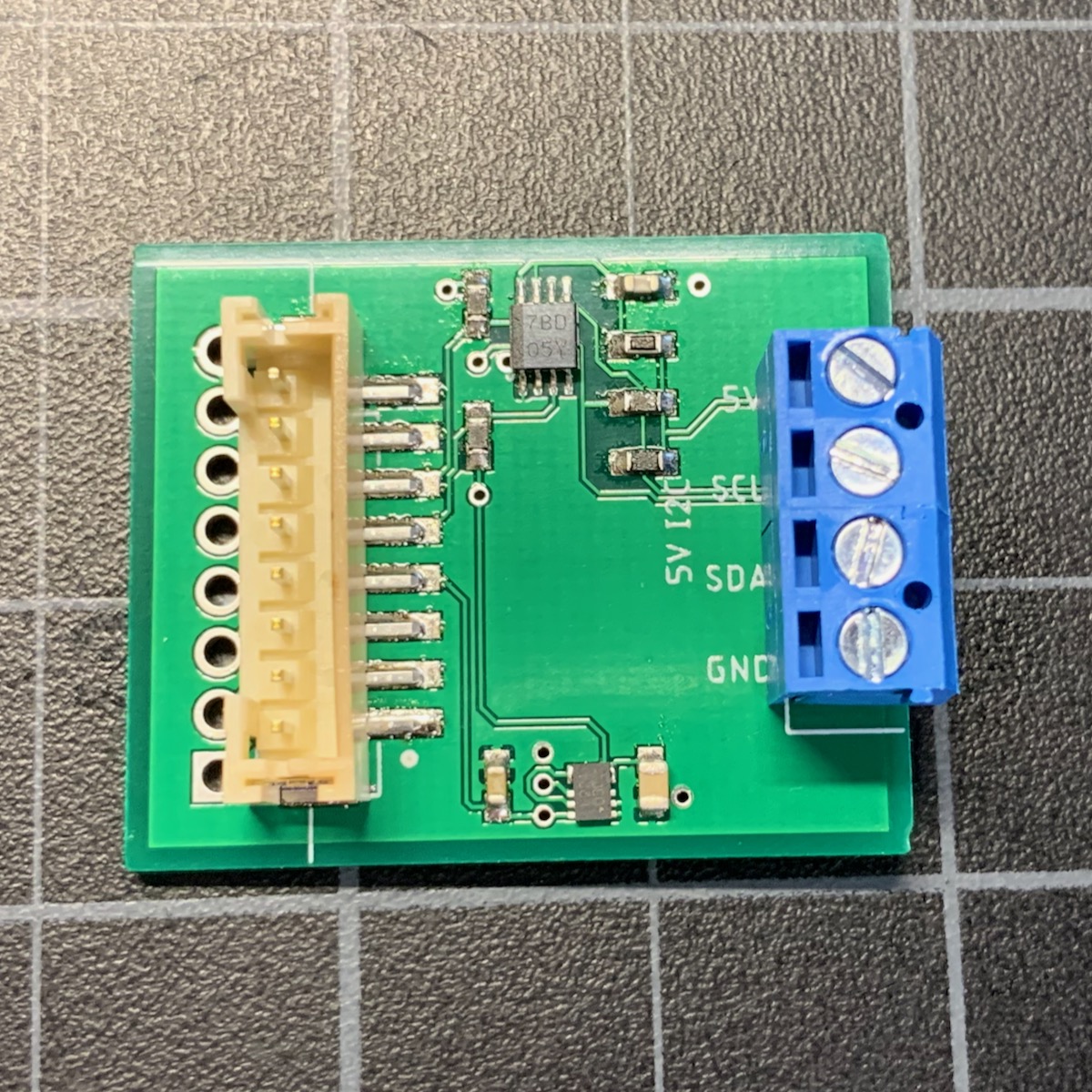
This example design is intended to be a prototype for illustration purposes only. It includes the same B8B-PH connector that is inside the Tracker One on the Tracker Carrier board. This allows the board to be connected to the carrier board using an inexpensive PHR-8 to PHR-8 cable.
Hardware design
Full design
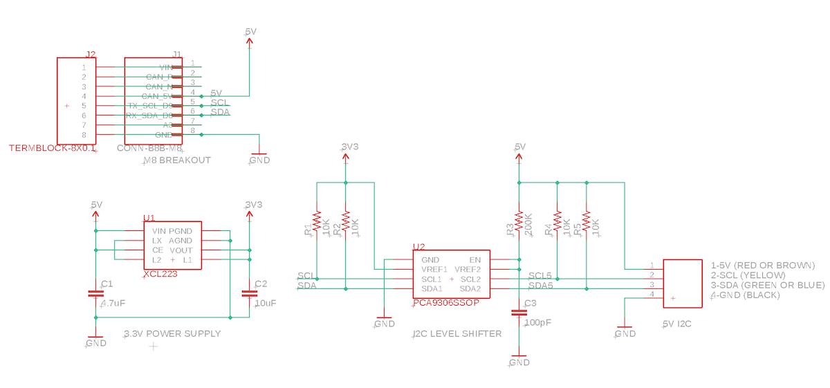
Schematic:
Board:
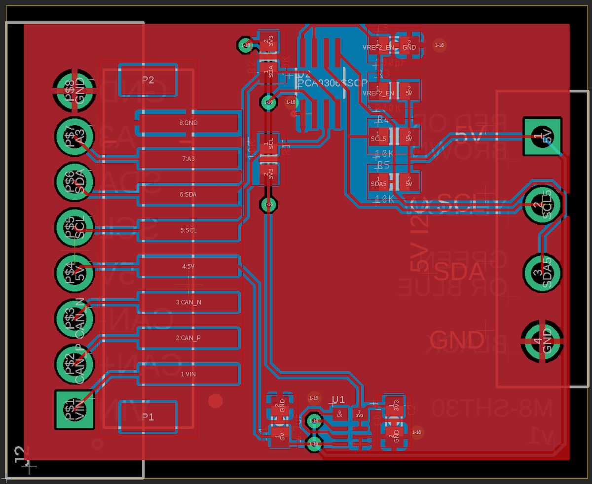
The Eagle CAD files for this design and the Gerber files are included in the eagle subdirectory.
BoM (Bill of Materials)
| Quantity | Part | Description | Example | Cost |
|---|---|---|---|---|
| 1 | C1 | Capacitor Ceramic 4.7uF 6.3V 0603 | Murata GRM188R60J475KE19J | |
| 1 | C2 | Capacitor Ceramic 10uF 16V 0805 | Murata GRM21BR61C106KE15L | |
| 1 | C3 | Capacitor Ceramic 100pF 50V 0603 | Kemet C0603C101J5GACTU | |
| 4 | R1, R2, R4, R5 | Resistor 10K 5% 1/4W 0603 | Panasonic ERJ-PA3J103V | |
| 1 | R3 | Resistor 200K 1% 1/10W 0603 | Panasonic ERJ-3EKF2003V | |
| 1 | U1 | XCL224 3.3V regulator | Torex XCL224A333D2-G | $ 2.43 |
| 1 | U2 | PCA9306SSOP | TI | $0.67 |
| 1 | J3 | TERM BLK 4POS SIDE ENT 3.5MM PCB | On Shore OSTTE040161 | $1.01 |
Choose one of:
| Quantity | Part | Description | Example | Cost |
|---|---|---|---|---|
| 1 | J1 | Conn SMD 8 position 2.00mm | JST B8B-PH-SM4-TB(LF)(SN) | $1.00 |
| J2 | Male Header Pins (8x0.1") | Sullins PRPC040SAAN-RC | ||
| 1 | J2 | Screw Terminal Block 8x0.1" PTH | On Shore OSTVN08A150 | $2.36 |
Regulator
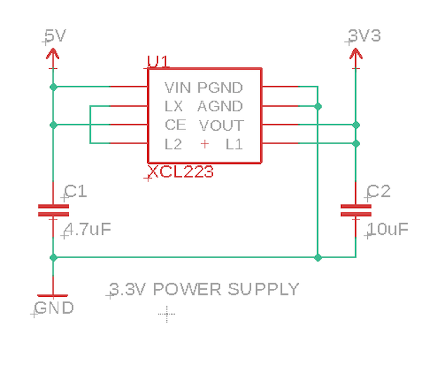
The M8 connector supplies 5V at 370 mA, and can be turned on and off using the CAN_PWR GPIO. There is a boost converter on the Tracker SoM and 5V is available off battery as well as USB and external VIN power.
Since the nRF52840 MCU only supports 3.3V logic levels on I2C, Serial, and GPIO, a 3.3V regulator is often required. This design uses a Torex XCL223 or XCL224. It's tiny, inexpensive, and does not require an external inductor, which saves space and BoM costs. It's a 700 mA regulator, but you'll be limited to the 370 mA on CAN_5V.
PCA9306
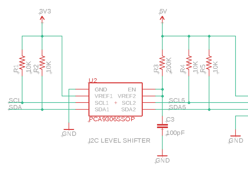
The SHT3x sensors require 5V, so we need to translate the 3.3V I2C on the Tracker SoM to 5V.
The nRF52 is not 5V tolerant! You cannot directly connect 5V I2C to it!
We use a PCA9306 I2C level-shifter. This converts between 3.3V and 5V logic. Note that I2C is bi-directional on both pins (SDA and SCL), so you can't just use a simple level-shifter.
Note that I2C requires pull-up resistors, and this design includes two sets, one to 3.3V and one to 5V, on either side of the PCA9306.
Adding sensors
There are a few commonly available SHT30 sensors:
Note that the color code printed on the PCB is for the Adafruit sensor. The sensor I got from Amazon had a different color code, so be careful!
Also be sure to use the SHT30, SHT31, etc.. The earlier sensors like the SHT10 are not compatible! The SHT10 looks the same but uses a proprietary protocol instead of I2C.
Firmware
Getting the Tracker Edge firmware
You can download a complete project for use with Particle Workbench as a zip file here:
Version:
- Extract tracker-an022.zip in your Downloads directory
- Open the tracker-an022 folder in Workbench using File - Open...; it is a pre-configured project directory.
- From the Command Palette (Command-Shift-P or Ctrl-Shift-P), use Particle: Configure Project for Device.
- If you are building in the cloud, you can use Particle: Cloud Flash or Particle: Cloud Compile.
- If you are building locally, open a CLI window using Particle: Launch CLI then:
particle library copy
Manually
The Tracker Edge firmware can be downloaded from GitHub:
https://github.com/particle-iot/tracker-edge
You will probably want to use the command line as there are additional commands you need to run after cloning the source:
git clone https://github.com/particle-iot/tracker-edge
cd tracker-edge
git submodule update --init --recursive
- Open Particle Workbench.
- From the command palette, Particle: Import Project.
- Run Particle: Configure Workspace for Device, select version 1.5.4-rc.1, 2.0.0-rc.3, or later, Tracker, and your device.
- Run Particle: Flash application (local).
Make sure you've used the Mark As Development Device option for your Tracker device in your Tracker product. If you don't mark the device as a development device it will be flashed with the default or locked product firmware version immediately after connecting to the cloud, overwriting the application you just flashed.
Add the sht3x-i2c library
From the command palette in Workbench, Particle: Install Library then enter sht3x-i2c.
The documentation for the library can be found here.
Customize main.cpp
Digging in
Sht3xi2c sensor(Wire3, 0x44);
Note that the M8 I2C interface is Wire3 not Wire as you might be used to on other Particle devices where Wire is on pins D0 and D1. On the Tracker M8 connector, Wire3 is on the same physical pins as Serial1 so you can only use one port or the other.
Tracker::instance().init();

// Register a location callback so we can add temperature and humidity information
// to location publishes
Tracker::instance().location.regLocGenCallback(myLocationGenerationCallback);
In setup() initialize the Tracker firmware and add a callback for when the location publishes occur.
// Turn on 5V output on M8 connector
pinMode(CAN_PWR, OUTPUT);
digitalWrite(CAN_PWR, HIGH);
delay(500);

sensor.begin(CLOCK_SPEED_400KHZ);
sensor.start_periodic();
The on CAN_PWR to power the regulator, level-shifter, and sensor. Then initialize the sensor.
Particle.connect();
Finally connect to the Particle cloud at the end of setup.
Tracker::instance().loop();
Make sure you give the Tracker Edge firmware processor time on every call to loop().
void myLocationGenerationCallback(JSONWriter &writer, LocationPoint &point, const void *context)
{
    double temp, humid;

    int err = sensor.get_reading(&temp, &humid);
    if (err == 0)
    {
        writer.name("sh31_temp").value(temp);
        writer.name("sh31_humid").value(humid);

        Log.info("temp=%.2lf hum=%.2lf", temp, humid);
    }
    else {
        Log.info("no sensor err=%d", err);
    }
}
Finally, when there is a location publish, add the sensor data to it.
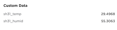
Cloud data
In the map view in the console, you should be able to see the additional custom data: