
E-Series evaluation board
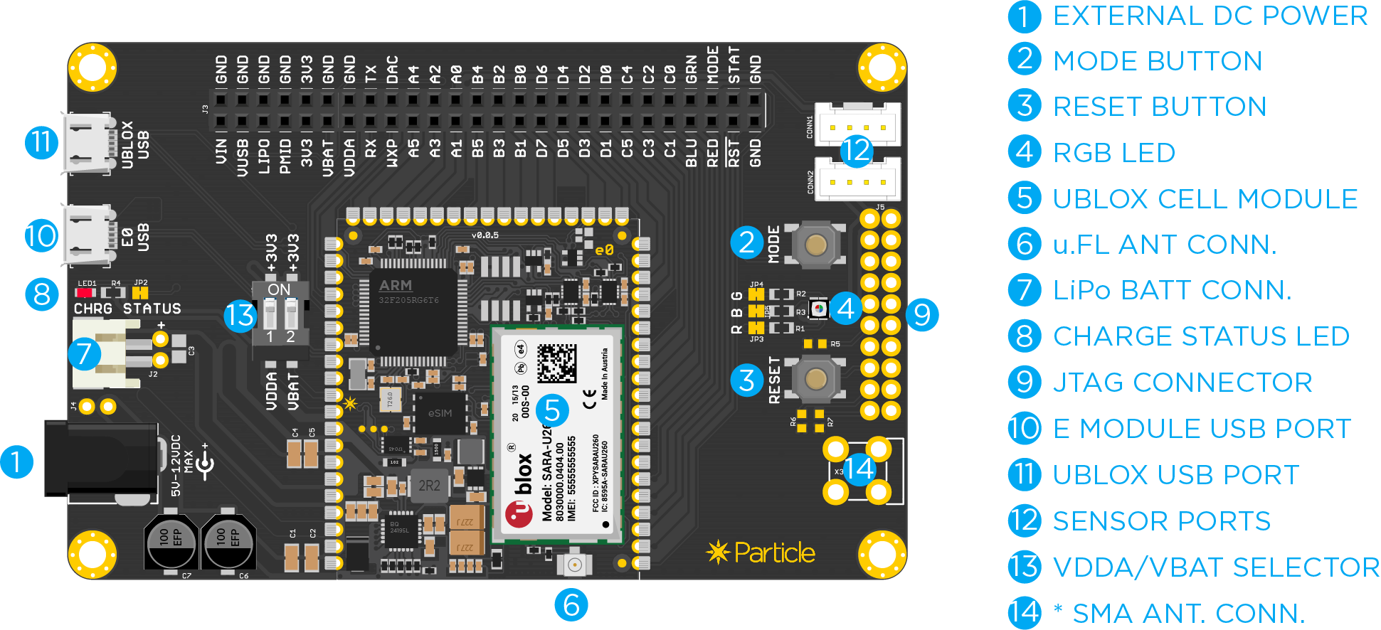
This is a simple breakout board for Particle's E series of cellular IoT modules. It breaks out all of its pins via easy to use headers. The board features a redundant USB port, connector for the LiPo battery, a barrel jack power connector, buttons, RGB LED, and charge status LED.
Description
| ID | Description |
|---|---|
| External Power | This is directly connected to the VIN pin. Minimum power requirements are 5VDC @500mA (when using the LiPo battery) or 5VDC @2000mA (without LiPo battery). |
| Mode Button | This is same as the MODE button on the Electron. |
| Reset Button | This is same as the RESET button on the Electron. |
| RGB LED enable | This switch allows you to enable or disable the on board RGB LED. All three pins (Red, Green, and Blue) are exposed individually. Flip all three to ON position if you want to use the on board RGB LED. |
| u-blox cell module | This is the u-blox SARA module. |
| uFl antenna connector | Plug the antenna here. |
| LiPo Battery connector | Plug in the LiPo battery here. |
| Charge status LED | This is same as the status LED on the Electron. |
| JTAG connector | This can plug directly into the STLink or the Particle programmer shield. |
| E Module USB port | This is the module's main USB port that connects to the STM32F microcontroller. |
| u-blox USB port | This USB port connects directly to the u-blox module. |
| Sensor ports | These are two grove compatible sensor ports. |
| VDD/VBAT selector | The dip switches should be flipped individually to the ON position if you want to power the VDDA and VBAT pins via the on board 3V3 supply. If you want to connect a different source, simply flip the switch to the OFF position and connect a suitable supply using the respective header pins. |
| **SMA Antenna connector | Optional SMA connector to attach other external antenna. |
Pin information
| PINS | FUNCTION | DESCRIPTION |
|---|---|---|
| VIN | POWER | This pin can be used as an input or output. As an input, supply 5VDC to 12VDC to power the Electron. When the Electron is powered via the USB port, this pin will output a voltage of approximately 4.8VDC due to a reverse polarity protection series Schottky diode between VUSB and VIN. When used as an output, the max load on VIN is 1Amp. |
| VUSB | POWER | This is connected to the VUSB power pin of the USB port. |
| LiPo | POWER | This is connected to the +LiPo connector. |
| PMID | POWER | This is connected to the PMID pin of the PMIC. |
| 3V3 | POWER | This is the output of the 3V3 regulator on the E series |
| GND | POWER | Common GND pin. |
| VDDA | POWER | This is the input to the analog block of the STM32. |
| VBAT | POWER | Supply to the internal RTC, backup registers and SRAM when 3V3 is not present (1.65 to 3.6VDC). |
| RED | IO | Red pin of the RGB LED. (PA1) |
| GRN | IO | Green pin of the RGB LED. (PA2) |
| BLU | IO | Blue pin of the RGB LED. (PA3) |
| RST | I | Active-low reset input. |
| MODE | IO | Connected to the MODE button input. |
| STAT | O | Connected to the charge status pin of the PMIC. |
| TX | IO | Primarily used as UART TX, but can also be used as a digital GPIO or PWM. |
| RX | IO | Primarily used as UART RX, but can also be used as a digital GPIO or PWM. |
| WKP | IO | Active-high wakeup pin, wakes the module from sleep/standby modes. When not used as a WAKEUP, this pin can also be used as a digital GPIO, ADC input or PWM. Can be referred to as A7 when used as an ADC. |
| DAC | IO | 12-bit Digital-to-Analog (D/A) output (0-4095), referred to as DAC or DAC1 in software. Can also be used as a digital GPIO or ADC. Can be referred to as A6 when used as an ADC. |
| A0-A5 | IO | 12-bit Analog-to-Digital (A/D) inputs (0-4095), and also digital GPIOs. A6 and A7 are code convenience mappings, which means pins are not actually labeled as such but you may use code like analogRead(A7). A6 maps to the DAC pin and A7 maps to the WKP pin. A3 is also a second DAC output used as DAC2 or A3 in software. A4 and A5 can also be used as PWM outputs. |
| B0-B5 | IO | B0 and B1 are digital only while B2, B3, B4, B5 are 12-bit A/D inputs as well as digital GPIOs. B0, B1, B2, B3 can also be used as PWM outputs. |
| C0-C5 | IO | Digital only GPIO. C4 and C5 can also be used as PWM outputs. |
| D0-D7 | IO | Digital only GPIO. D0, D1, D2, D3 can also be used as PWM outputs. |
Basic setup
The basic setup for the E series to be operational is shown below:
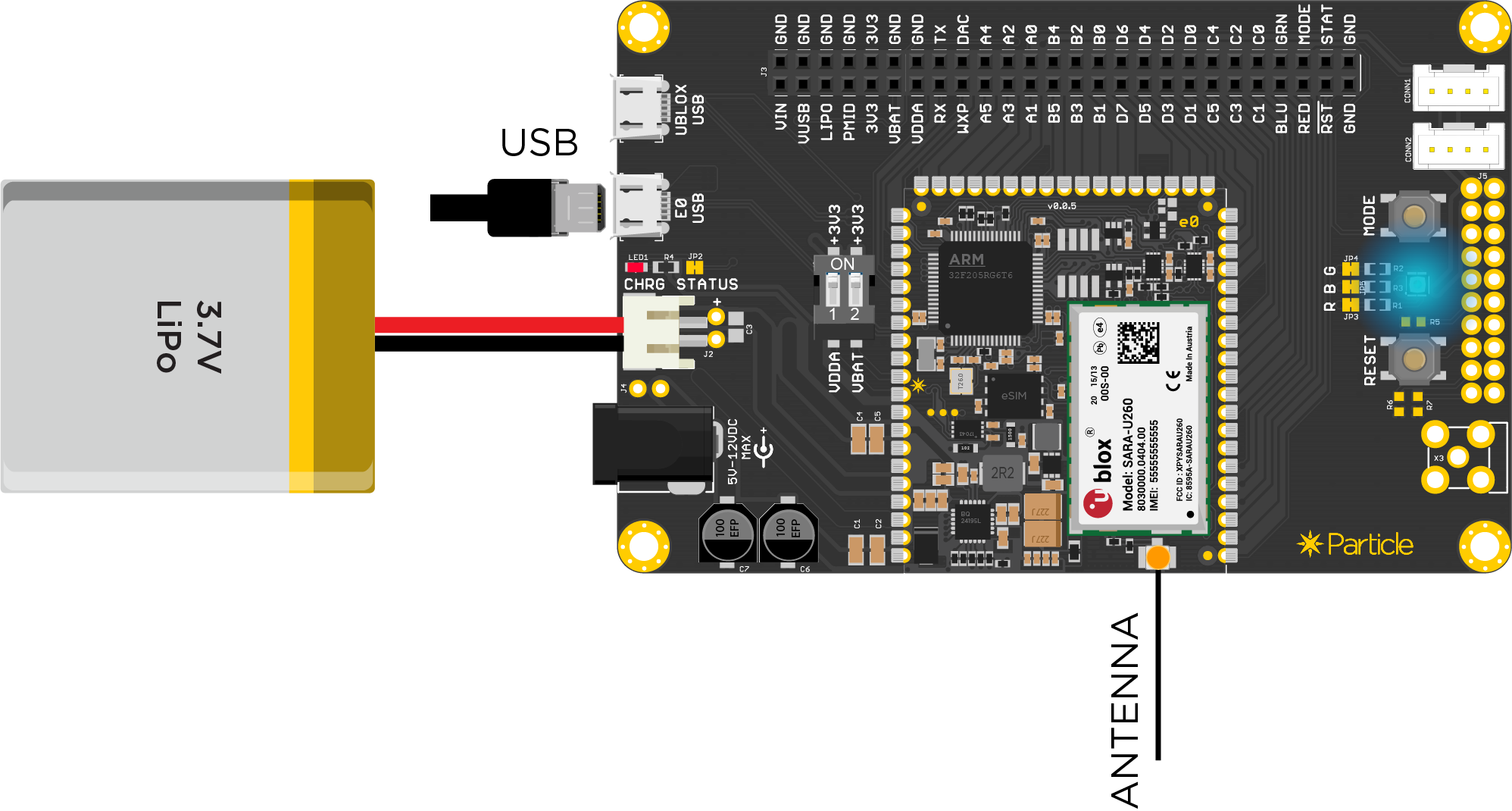
Plug the antenna into the uFL connector. Remember never to power up the Electron or this board without the antenna being connected. There is potential to damage the transmitter of the u-blox module if no antenna is connected.
To power the board you can either use the barrel jack connector or the E series USB port. If you are planning to power the board without the LiPo battery, remember that the power supply should be able to source at least 2A @5VDC.
VDDA/VBAT selector switch:
The dip switches should be flipped individually to the ON position if you want to power the VDDA and VBAT pins via the on board 3V3 supply. If you want to connect a different source, simply flip the switch to the OFF position and connect a suitable supply using the respective header pins.
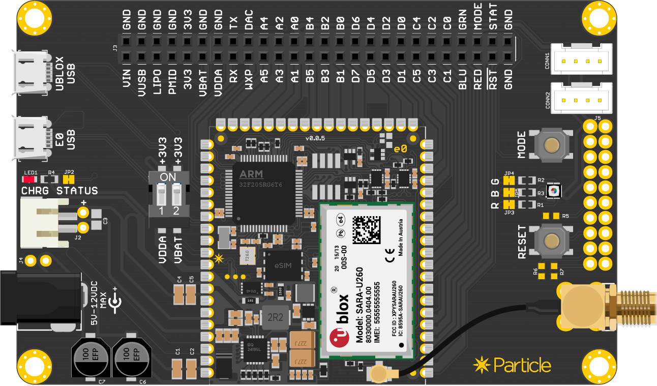
SMA Connector: The evaluation kit comes with a solderable U.FL to SMA adapter. You can optionally solder it on to the board and connect a different cellular antenna of your choice.
Sensor Ports:
There are two 4-pin connectors available for you to plug in Grove compatible sensors. CONN1 exposes two analog pins (A0 and A1) while CONN2 exposes the I2C pins (D0 and D1).
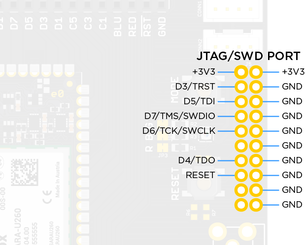
JTAG/SWD connector:
We have included a standard 20 pin JTAG/SWD connector footprint. You can use this port to gain direct access to the onboard microcontroller.
CR2302 connector:
We have provided a footprint to solder on a CR2302 coin cell holder on the bottom. This can help you power the VBAT pin of the microcontroller using a coin cell if needed. If you do end up soldering one, please remember to toggle the DIP switch that connects VBAT to 3V3 to OFF position.
That's it! The rest of the development process should be similar to that of the Electron.
Ordering information
| SKU | Description | Region | Modem | EtherSIM | Lifecycle | Replacement |
|---|---|---|---|---|---|---|
| E314KIT | E-Series 2G/3G (Global - E314) Evaluation Kit, [x1] | Global | U201 | ✓ | NRND | |
| E402KIT | E-Series LTE CAT-M1 (NorAm) Evaluation Kit, [x1] | NORAM | R410 | NRND | ||
| E404KIT | E-Series LTE-M (NorAm, EtherSIM) Evaluation Kit, [x1] | NORAM | R410 | ✓ | NRND |