
Tachyon Datasheet
Overview
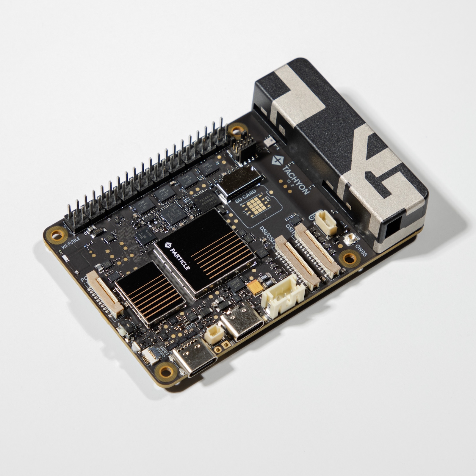
Tachyon is a 5G-connected single-board computer (SBC) that takes the technology inside a modern smartphone and packs it into a Raspberry Pi form factor to power portable and remote computing devices. With a powerful Qualcomm Dragonwing™ SoC, an AI accelerator, and Particle’s application infrastructure, Tachyon combines all of the edge computing power, connectivity, and software necessary to embed intelligence into anything, anywhere.
- Qualcomm QCM6490 8-core Kryo™ 670 CPU (1x 2.7GHz, 3x 2.4GHz, 4x 1.9GHz).
- 5G sub-6Hz cellular connectivity and Wi-Fi 6E with on-device antennas
- 8GB RAM/128GB flash with built-in UFS storage (TACH8NA, TACH8ROW)
- 4GB RAM/64 GB flash with built-in UFS storage (TACH4NA)
- Adreno 643 GPU and 12 TOPS NPU
- USB-C 3.1 PD with DisplayPort and PD, 2x PCIe lanes, and DSI 4-lane
- 2 x CSI 4-lane with ISP, supporting 20+ pre-integrated camera sensors
- Powered by USB-C or lithium-ion battery with integrated battery charger
- Secure boot and encrypted filesystem
Additional resources
CPU information
AI Engine
| GPU Name | Qualcomm® Adreno™ 643L |
| CPU Name | Qualcomm® Adreno™ 643L |
| GPU Name | Qualcomm® Kryo™ 670 |
| Qualcomm® Hexagon™ Processor Name | Qualcomm® Hexagon™ 770 |
| Qualcomm® Hexagon™ Processor Features | Qualcomm® Hexagon™ Tensor Accelerator Qualcomm® Hexagon™ Scalar Accelerator Qualcomm® Hexagon™ Vector eXtensions (HVX) Qualcomm® Hexagon™ Voice Assistant Accelerator Large shared AI memory |
| Qualcomm® Sensing Hub Generation | 2nd |
| Qualcomm® Sensing Hub Features | Qualcomm® Sensing Hub |
| Tera Operations Per Second (TOPS) | 12 TOPS |
CPU
| Name | Qualcomm® Kryo™ CPU, Qualcomm® Kryo™ 670 |
| Number of cores | 8 |
| Architecture | 64-bit |
| Clock speed | 1x 2.7GHz, 3x 2.4GHz, 4x 1.9GHz |
GPU
| Name | Qualcomm® Adreno™ 643L |
| Clock Speed | Up to 812 MHz |
| APIs | OpenGL® ES 3.2 DirectX® FL 12 OpenCL™ 2.0 FP Vulkan® 1.1 |
DSP
| Name | Qualcomm® Hexagon™ |
Location
| Sensor-assisted Positioning | Sensor-assisted Positioning |
| Satellite Systems | GLONASS, NavIC, QZSS, Galileo, Beidou, SBAS, GPS |
| Frequency Support | Dual (L1/L5) |
| Accuracy | Lane-level, Sidewalk-level |
| Features | Global Freeway Vehicle Navigation |
Radio
- Quectel SG560D-NA or SG560D-EM radio module
- 3GPP Rel-15 specification, and supports both 5G NSA and SA modes with 4G/ 3G fallback
- 5G & LTE cellular technology
- Wi-Fi 6E & DBS, IEEE 802.11a/ b/ g/ n/ ac/ ax, Wi-Fi 2
- Bluetooth 5.2
Antennas
The Tachyon includes built-in antennas for:
- Cellular
- Wi-Fi (2.4 GHz and 5 GHz) and BLE
The Tachyon includes a U.FL connector for:
- GNSS (GPS)
Wi-Fi operation in the 5150-5250 MHz band is only for indoor use to reduce the potential for harmful interference to co-channel mobile satellite systems.
Power
Power can be supplied by:
- Primary USB-C (USB1)
- LiPo battery (3-pin JST-PH connector)
- 40-pin expansion HAT connector (5V)
When powering from the HAT connector you cannot use Primary USB-C (USB1) at the same time.
The HAT as a power source can be used in two ways:
- A minimum of 5A is required (at 5VDC) to use Tachyon with only HAT power (no battery).
- It is also possible to use HAT power to charge a battery, for example using a 5V solar battery charger.
For additional details, see power requirements, below.
Connections
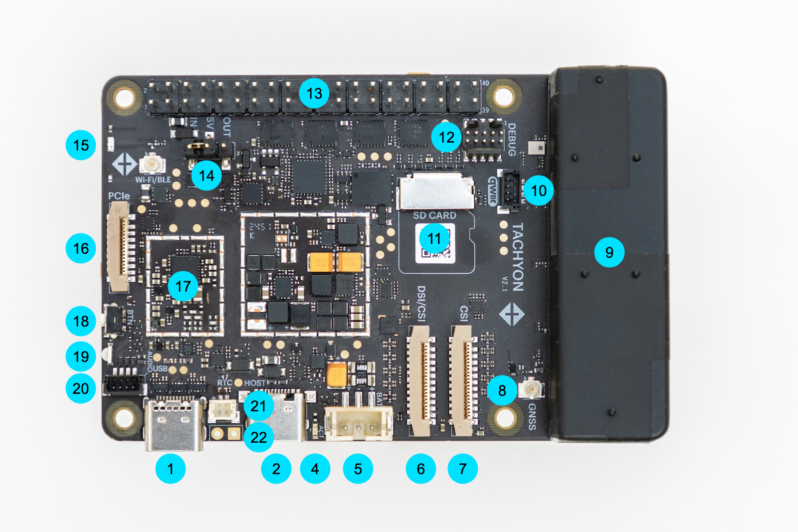
| Label | Description | |
|---|---|---|
| 1 | Primary USB (USB1) | |
| 2 | Secondary USB (USB2) | |
| 4 | Activity LED | |
| 5 | LiPo battery connector | |
| 6 | DSI/CSI connector - DISP_CAM1 (display or camera) | |
| 7 | CSI connector - CAM2 (camera only) | |
| 8 | GNSS antenna | |
| 9 | Built-in cellular antenna | |
| 10 | QWIIC connector (3.3V I2C) | |
| 11 | SD card (optional) | |
| 12 | Debug connector (optional) | |
| 13 | Raspberry Pi 40-pin expansion HAT connector | |
| 15 | Wi-Fi chip antenna | |
| 16 | PCIe expansion connector | |
| 18 | Button (power and mode) | |
| 19 | Primary LED | |
| 20 | Audio card connector | |
| 21 | RTC battery connector (optional) | |
| 22 | Connection for external button (optional) |
Primary USB (USB1) (1)
- Supports USB 3.1 (Key Port)
- Power & Data
- Supports USB Power Delivery (USB PD) for powering the device.
- Functions as a USB host or USB device depending on connection type.
- Video Output & Adapter Support
- Supports USB-C adapters that combine USB, power, and HDMI output.
- Acts as a PD sink when using a usb-c hub adapter.
- Can output HDMI over USB-C hub.
- For additional details, see power requirements, below.
Secondary USB (USB2) (2)
- USB 2.0 only.
- Standard USB-C connectivity.
- Supports USB hubs and can provide 5V power to connected devices.
Activity LED (4)
The Activity LED (4), located near the USB ports, provides system-level feedback, including disk operations, network activity, and battery charging status.
LiPo battery connector (5)
The Tachyon uses a 3.7V LiPo battery with a 3-pin JST-PH connector. The pack contains a 10K NTC thermistor temperature sensor.
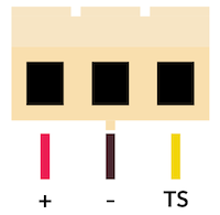
Facing the plug on the battery side
DSI/CSI connector - DISP_CAM1 (display or camera) (6)
- This MIPI connection port supports either a camera or display
- Aligns with Raspberry Pi implementations for MIPI camera/display adapters.
- You can either use two cameras or one camera and one display using the two MIPI ports
- Based on 4-lane MIPI DSI, supports up to 2.5 Gbps/ lane, (1200 × 2520) @ 144 fps
- Supports DisplayPort 1.4, up to 4K (3840 × 2160) @ 60 fps
- Supports Wi-Fi Miracast 4K @ 60 fps
CSI connector - CAM2 (camera only) (7)
- This MIPI connection port supports a camera
- Aligns with Raspberry Pi implementations for MIPI camera/display adapters.
- 4 × 4-lane MIPI CSI, up to 2.5 Gbps/ lane
- 3 × ISP, up to 3 × 27 MP @ 24 fps or 3 × 22 MP @ 30 fps; 36 MP + 27 MP @ 24 fps or 36 MP + 22 MP @ 30 fps; 36 MP @ 30 fps
GNSS antenna (8)
- The recommended antenna is the
PARANTGN1, included in your alpha tester kit. - If using your own active antenna, the LNA gain must be less than 17dB.
- Software support will be provided in a future release.
Built-in cellular antenna (9)
- This module contains the Wi-Fi and cellular antennas.
- Do not attempt to open the antenna module as it is very difficult to reassemble.
QWIIC connector (3.3V I2C) (10)
- Follows the SparkFun Qwiic/Adafruit STEMMA QT standard for easy I2C expansion.
- Enables connection to various sensors and peripherals.
- Sensors and peripherals can generally be daisy-chained together.
- 4-pin JST 1mm connector, keyed.
- 3.3V I2C.
There is additional information on the Qwiic ecosystem in the Qwiic page in the Particle docs. Note that since Tachyon is Linux-based, you will need different libraries than you would for Particle or Arduino, but there are libraries for many popular Qwiic boards.
SD card (optional) (11)
- Plug in any standard SD card into this slot.
- Optional for user data storage; operating system is stored on internal flash memory.
- SD 3.0, supports 4-bit SDIO
Debug connector (optional) (12)
- Provides UART access for system debugging and interaction.
- Used for:
- SysCon UART (system controller communication).
- Linux module UART (direct serial console access).
- Battery communication (if applicable).
This connectors attaches to the debug adapter using a 10-pin (2x5) ribbon cable.
Raspberry Pi 40-pin expansion HAT connector (13)

- I2C (also connected to Qwiic port)
- SPI
- UART serial
- All GPIO are 3.3V only (not 5V tolerant outside of the 5V power pin)
The 5V pins on the 40-pin HAT connector can be used as an output (when powered by battery or USB), or as an input (powering Tachyon from the HAT). See Power, above.
When supplying power to the HAT, the 5V power is limited to 1.5A. It can operate most peripheral cards, but high current cards like motor HATs may not work.
For additional details about using 5V as a power input, see power requirements, below.
Wi-Fi chip antenna (15)
- Dual-band Wi-Fi and BLE chip antenna.
Alpha versions of the Tachyon have a U.FL connector marked Wi-Fi/BLE. This connector is not operational and will be removed in future versions of the Tachyon.
PCIe expansion connector (16)
- PCIe 3.0 x1 slot
- Matches the Raspberry Pi PCIe implementation.
- 2-lane PCIe Gen 3, supports NVMe
Button (power and mode) (18)
The Tachyon board has a single button (18), located next to the primary LED, which is used for managing device states. It allows users to power on, enter programming mode, suspend, wake up, force power off, and trigger custom actions in user space.
Primary LED (19)
The primary LED (19) on the Tachyon board provides critical information about the device’s current mode and status.
The LED indicates:
- The Tachyon’s core mode (e.g., off, standby, update, or operation).
- The Tachyon’s status within that mode (e.g., booting, connected, or error states).
Audio card connector (20)
- This is a 4 pin connector that gives analog audio in / out on the Tachyon board
- Software support will be added in a future release
RTC battery connector (optional) (21)
- Uses RTC modules for the Raspberry Pi that typically contain a Lithium coin cell battery.
- Helps retain time between power cycles but does not provide full power-loss protection.
Connection for external button (optional) (22)
- Connect these two pads to an external momentary switch to allow the button operations to be done from an external button.
Power requirements
The Tachyon supports three power inputs:
- USB1 (primary USB-C)
- 5V IN (input from the 40-pin expansion HAT connector)
- VBAT (LiPo battery)
It supports different USB power modes:
- PD (Power Delivery)
- DCP (Dedicated Charge Port)
- CDP (Charging Downstream Port).
Power from USB1 can be added or removed while the Tachyon is running.
You should avoid adding or removing 5V IN or the battery while the system is running as the change may not be detected, or the device may turn off unexpectedly.
The USB1 port has a DP (DisplayPort) function for connecting to an external monitor via an USB-C to C cable. It is highly recommended the monitor have its own power supply to prevent high current from the USB1 port. The port can supply about 5V/1.5A to USB devices.
Power input requirements
- USB1: There are different modes for supplying power to the USB-C port and its power capability from a USB-C power adapter and USB port of a computer
- DCP: 5V/3A or 9V/3A
- CDP: 5V/1.5A
- PD: 5V/5A or 9V/3A
- 5V IN: Input from the 40-pin HAT connector
- 5V/5A (do not provide voltage higher than 5V from the 40-pin connector)
- VBAT: Battery
- 3.5V - 4.2V
Notes:
- If both the USB1 and 5V (as input) have power to supply to the board at the same time without battery attached, the 5V power will supply to VBAT (simulates battery).
- If 5V is used as power input with battery attached, the USB1 port cannot be used.
- If 5V is not used for power input, it is set to power output and supplies 5V/1.5A to the 40-pin expansion HAT connector.
Power modes
The Tachyon supports the following power modes of operation
- DCP
- Powered by power adapter with DCP capability
- This mode can work without battery attached
POWER_SUPPLY_TYPE=USB_DCP
- CDP
- Powered by computer USB-A port, data communication is functional
- Powered by computer USB-C to A adapter and A to C cable to the board, data communication is functional
- Limited power but useful for sending data or debugging, e.g. adb shell
POWER_SUPPLY_TYPE=USB_CDP
- PD
- Powered by power adapter with USB-PD capability
- Powered by computer USB-C Port, data communication is functional
- This mode can work without battery attached, see Older power requirements, below.
POWER_SUPPLY_TYPE=USB_PD
- Battery
- Battery is discharging
Known issues:
- CDP/PD: If the board has no battery attached and connects to the computer USB-C port via USB-C to C cable, the Tachyon will use PD instead of CDP.
- DCP: The power adapter shipped with beta devices supports PD only and is not DCP capable, so it must be used with a battery or 5V input.
Power supply scenarios
| USB1 | 5V IN | VBAT | Power Requirements | Notes |
|---|---|---|---|---|
| Power Adapter | NO | NO | PD: Not Supported | 5V is set to power output - 5V/1.5A |
| DCP: 9V/3A or 5V/5A | Power adapter with PD only see 4 | |||
| Power Adapter | YES | NO | PD: 9V/3A | Power comes from USB1 |
| DCP: 9V/3A or 5V/5A | Remove USB1, power will change to 5V2 | |||
| Power Adapter | YES | YES | PD: 9V/3A | Power comes from USB1 |
| DCP: 9V/3A or 5V/5A | Remove USB1, power will change to use VBAT13 | |||
| Power Adapter | NO | YES | PD: 9V/3A | |
| DCP: 9V/3A or 5V/5A | ||||
| PC USB (A to C cable) | NO | NO | CDP: 5V/1.5A | Power comes from USB1 Limited power supply for peripherals |
| PC USB (A to C cable) | YES | NO | CDP: 5V/1.5A | Power comes from 5V (via VBAT as fake battery) |
| Limited power supply for peripherals | ||||
| PC USB (A to C cable) | YES | YES | CDP: 5V/1.5A | Power comes from USB1 |
| Remove USB1, power will change to use VBAT 5V13 | ||||
| PC USB (A to C cable) | NO | YES | CDP: 5V/1.5A | Power comes from USB1 and to VBAT |
| PC USB (C to C cable) | YES | YES | PD: 5V/3A | Power comes from USB1 Remove USB1, power will change to use VBAT 13 |
| PC USB (C to C cable) | YES | NO | PD: 5V/3A | Power comes from USB1 Remove USB1, power will change to use 5V 2 |
| PC USB (C to C cable) | NO | NO | PD: See 4 | |
| PC USB (C to C cable) | NO | YES | PD: 5V/3A | Power comes from USB1 and to VBAT |
| NO | YES | YES | 5V/5A | Power supplies to VBAT |
| After boot-up, USB1 will not be functional | ||||
| System only reports DCP 5V/3A | ||||
| NO | YES | NO | 5V/5A | Power supplies to VBAT |
| After boot-up, USB1 will be functional for USB device and display | ||||
| N/A | N/A | YES | 3.5V - 4.2V / 5A |
1Battery will be discharging in this mode.
2VBAT is powered, simulating a battery, even though a battery is not connected.
35V input is not used.
4Requires 24.04 (Release v1.1.32), 20.04 (Release v1.0.180), or later. Earlier versions will not boot.
Connect power input(s) before booting Tachyon to insure proper detection.
Older power requirements
In version 24.04 (Release v1.1.32) and 20.04 (Release v1.0.180) support was added for powering in USB-C PD mode without requiring a battery:
No-battery (USB-Powered) mode: The device can be powered via the USB1 port (USB-C) without a battery attached. USB-C Power Delivery is supported for negotiating adequate power from a host or charger, and this does not require an external Power Delivery controller chip on the accessory. This mode is useful for bench testing or situations where the device is stationary and can be powered continuously via USB-C.
The information above has been updated to reflect this. You may see references elsewhere to a battery being required when using USB-C PD mode. This is no longer necessary once you've upgraded to these releases, but will still be required when using an older version, or upgrading from an older version.
When using older releases, the following power requirements apply:
- With older versions when using USB-PD mode, a battery (or 5V in) must also be used or the Tachyon will not boot properly.
- The USB-DCP mode can be used without a battery as the sole power source.
- If the Tachyon is connected to a HDMI dock, USB hub, or monitor via the USB1 connector, USB-PD mode will be used, and a battery is required when using older versions.
Power requirements summary
- USB power adapter can support
- USB-PD at 9V/3A (must use with battery or 5V at the same time)
- USB-DCP at 9V/3A
- Supply 5V/5A to the 40-pin header for power input
- Use a battery if possible (with capacity from a minimum of 3.5V to a maximum 4.2V with 5A capability)
Technical specification
I/O Characteristics
The CPU runs at 1.8V, but I/O on the expansion HAT connector is is 3.3V. Levels are translated using TI TXS0108E bidirectional level translators.
- Maximum data rates:
- 110Mbps (push-pull)
- 1.2Mbps (open-drain)
- 1.65V to 5.5V on B port
- ESD protection exceeds JESD 22 (A port, CPU-side):
- 2000 V Human Body Model (A114-B)
- 150 V Machine Model (A115-A)
- 1000 V Charged-Device Model (C101)
- IEC 61000-4-2 ESD (B port, expansion connector side):
- ± 8kV Contact Discharge
- ± 6kV Air Discharge
Absolute maximum ratings
These values are from the TXS0108E datasheet and assume VCCB is 3.3V.
| Parameter | Min | Max | Unit |
|---|---|---|---|
| Input voltage | -0.5 | 6.5 | V |
| Voltage applies to any output in high or low state | -0.5 | 3.8 | V |
| Input clamp current IK | -50 | mA | |
| Output clamp current IOK | -50 | mA | |
| Continuous output current IO | -50 | 50 | mA |
| Continuous output current IO | -50 | 50 | mA |
Recommended operating conditions
| Parameter | Min | Max | Unit |
|---|---|---|---|
| High-level input voltage VIH | 2.9 | 3.3 | V |
| Low-level input voltage VIL | 0 | 0.15 | V |
| Input transition rise or fall rate Δt/Δv | 10 | ns/V |
Timing requirements
| Parameter | Test Conditions | Min | Max | Unit | |
|---|---|---|---|---|---|
| Data rate | Push-pull driving | 70 | Mbps | ||
| Open-drain driving | 0.8 | ||||
| tW | Pulse duration, data inputs | Push-pull driving | 15.3 | ns | |
| Open-drain driving | 1250 | ||||
Switching characteristics
| Parameter | Test Conditions | Min | Max | Unit | ||
|---|---|---|---|---|---|---|
| tPHL | Propagation delay time | Output | Push-pull driving | 5.7 | ns | |
| (high-to-low output) | Open-drain driving | 3.1 | 9.3 | |||
| tPLH | Propagation delay time | Output | Push-pull driving | 6.5 | ns | |
| (low-to-high output) | Open-drain driving | 126 | 486 | |||
| tPHL | Propagation delay time | Input | Push-pull driving | 7.4 | ns | |
| (high-to-low output) | Open-drain driving | 2.5 | 7.3 | |||
| tPLH | Propagation delay time | Input | Push-pull driving | 5.8 | ns | |
| (low-to-high output) | Open-drain driving | 129 | 459 | |||
| trB | Input rise time | B-port rise time | Push-pull driving | 1.2 | 5.2 | ns |
| Open-drain driving | 73 | 546 | ||||
| tfB | Input fall time | B-port fall time | Push-pull driving | 0.9 | 3.9 | ns |
| Open-drain driving | 1 | 9.6 | ||||
| tSK(O) | Skew (time), output | Channel-to-channel | Push-pull driving | 1 | ns | |
| Maximum date rate | A or B | Push-pull driving | 60 | Mps | ||
| Open-drain driving | 0.8 | |||||
Radio specifications
Frequency bands
| Frequency Bands | North America (TACH4NA/TACH8NA) | Rest of World (TACH8ROW) |
| 5G SA/NSA | n2/ 5/ 7/ 12/ 13/ 14/ 25/ 26/ 29/ 30/ 38/ 41/ 48/ 66/ 70/ 71/ 77/ 78 | n1/ 3/ 5/ 7/ 8/ 20/ 28/ 38/ 40/ 41/ 77/ 78/ 79 |
| LTE | B2/ 4/ 5/ 7/ 12/ 13/ 14/ 17/ 25/ 26/ 29/ 30/ 38/ 41/ 42/ 43/ 46/ 48/ 66/ 71 | B1/ 2/ 3/ 4/ 5/ 7/ 8/ 12/ 17/ 18/ 19/ 20/ 26/ 28/ 32/ 34/ 38/ 39/ 40/ 41/ 42 |
| LTE MIMO | 4 × 4 MIMO (DL): B2/ 4/ 7/ 25/ 30/ 38/ 41/ 42/ 43/ 48/ 66 | 4 × 4 MIMO (DL): B1/ 3/ 7/ 38/ 40/ 41/ 42 |
| WCDMA | - | B1/ 2/ 4/ 5/ 6/ 8/ 19 |
| GSM/EDGE | - | B2/ 3/ 5/ 8 |
| WLAN | 2.4 & 5 & 6 GHz 802.11a/ b/ g/ n/ ac/ ax, Supports DBS |
2.4 & 5 & 6 GHz 802.11a/ b/ g/ n/ ac/ ax, Supports DBS |
| Bluetooth | Bluetooth 5.2 | Bluetooth 5.2 |
| GNSS | GPS/ GLONASS/ BDS/ NavIC/ Galileo/ QZSS/ SBAS; L1 + L5 |
GPS/ GLONASS/ BDS/ NavIC/ Galileo/ QZSS/ SBAS; L1 + L5 |
Data rate
| Data rate | North America (TACH4NA/TACH8NA) | Rest of World (TACH8ROW) |
| 5G SA | 2.1 Gbps (DL)/ 900 Mbps (UL) | 2.1 Gbps (DL)/ 900 Mbps (UL) 9 |
| 5G NSA | 2.5 Gbps (DL)/ 550 Mbps (UL) | 2.5 Gbps (DL)/ 550 Mbps (UL) |
| LTE | 1.2 Gbps (DL)/ 200 Mbps (UL) | 1.2 Gbps (DL)/ 200 Mbps (UL) |
| DC-HSPA+ | 42 Mbps (DL)/ 5.76 Mbps (UL) | 42 Mbps (DL)/ 5.76 Mbps (UL) 2 |
| WCDMA | - | 384 kbps (DL)/ 384 kbps (UL) |
| EDGE | - | 296 kbps (DL)/ 236.8 kbps (UL) |
| GSM | - | 107 kbps (DL)/ 85.6 kbps (UL) |
Mechanical specifications
Operating temperature
| Parameter | Minimum | Maximum | Notes |
|---|---|---|---|
| Recommended operating temperature | -17°C | +65°C | 1 |
| Battery charging enabled | 0°C | +55°C | |
| Storage temperature | -40°C | +85°C |
1Device will perform thermal shutdown below -20°C or above +70°C.
Dimensions and Weight
- Dimensions: 85mm x 56mm
- Weight: 55g (approximate)
- Height: 18.5mm (from top of antenna to bottom of feet)
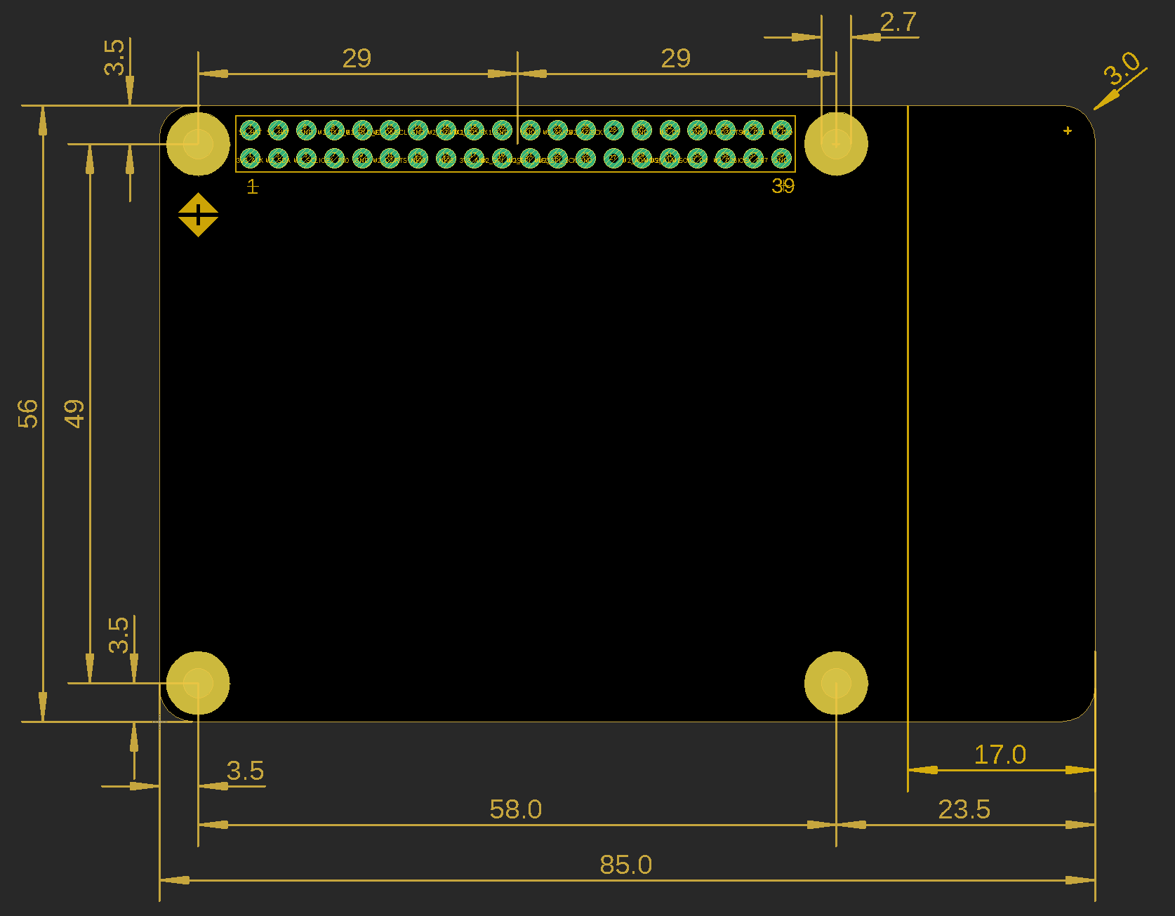
Dimensions are in millimeters.
3D models
A 3D model of the Tachyon is available in the hardware-libraries Github.
Product Handling
ESD Precautions
The M-SoM contains highly sensitive electronic circuitry and is an Electrostatic Sensitive Device (ESD). Handling an M-SoM without proper ESD protection may destroy or damage it permanently. Proper ESD handling and packaging procedures must be applied throughout the processing, handling and operation of any application that incorporates the Particle M-SoM. ESD precautions should be implemented on the application board where the M-SoM is mounted. Failure to observe these precautions can result in severe damage to the M-SoM!
Connectors
The 40-pin expansion had connector is static sensitive and should be handled carefully.
FCC ISED CE Warnings and End Product Labeling Requirements
FCC Supplier's Declaration of Conformity
47 CFR § 2.1077 Compliance Information
Responsible party:
Particle Industries, Inc.
325 9th St
San Francisco, CA 94103
This device complies with Part 15 of the FCC Rules. Operation is subject to the following two conditions: (1) This device may not cause harmful interference, and (2) this device must accept any interference received, including interference that may cause undesired operation.
FCC Radiation Exposure Statement
This equipment has been tested and found to comply with the limits for a Class B digital device, pursuant to Part 15 of the FCC Rules. These limits are designed to provide reasonable protection against harmful interference in a residential installation. This equipment generates, uses and can radiate radio frequency energy and, if not installed and used in accordance with the instructions, may cause harmful interference to radio communications. However, there is no guarantee that interference will not occur in a particular installation. If this equipment does cause harmful interference to radio or television reception, which can be determined by turning the equipment off and on, the user is encouraged to try to correct the interference by one of the following measures:
- Reorient or relocate the receiving antenna.
- Increase the separation between the equipment and receiver.
- Connect the equipment into an outlet on a circuit different from that to which the receiver is connected.
- Consult the dealer or an experienced radio/TV technician for help.
FCC Radiation Exposure Statement: This equipment complies with FCC radiation exposure limits set forth for an uncontrolled environment. This transmitter module must not be co-located or operating in conjunction with any other antenna or transmitter. This End equipment should be installed and operated with a minimum distance of 20 centimeters between the radiator and your body.
This Transmitter must not be co-located or operating in conjunction with any other antenna or transmitter.
FCC Indoor Use
FCC regulations restrict the operation of this device to indoor use only. This device is prohibited from being operated on oil platforms, cars, trains, boats, and aircraft, except it can be operated in large aircraft while flying above 10,000 feet in the 5.925-6.425 GHz band.
Transmitters in the 5.925-7.125 GHz band are prohibited from operating to control or communicate with unmanned aircraft systems
IMPORTANT NOTE: In the event that these conditions can not be met (for example certain laptop configurations or co-location with another transmitter), then the FCC authorization is no longer considered valid and the FCC ID can not be used on the final product. In these circumstances, the OEM integrator will be responsible for re-evaluating the end product (including the transmitter) and obtaining a separate FCC authorization.
End Product Labeling The final end product must be labeled in a visible area with the following:
- Contains FCC ID: 2AEMI-TACHYON
Manual Information to the End User The OEM integrator has to be aware not to provide information to the end user regarding how to install or remove this RF module in the user’s manual of the end product which integrates this module.
Outdoor Use (US)
To be compliant to FCC §15.407(a) the EIRP is not allowed to exceed 125 mW (21 dBm) at any elevation angle above 30° (measured from the horizon) when operated as an outdoor access point in U-NII-1 band, 5.150-5.250 GHz.
Canada Statement This device complies with Innovation, Science, and Economic Development Canada’s licence-exempt RSSs. Operation is subject to the following two conditions:
- This device may not cause interference; and
- This device must accept any interference, including interference that may cause undesired operation of the device.
Le présent appareil est conforme aux CNR d’Innovation, Sciences et Développement économique Canada applicables aux appareils radio exempts de licence.
L’exploitation est autorisée aux deux conditions suivantes:
- l’appareil ne doit pas produire de brouillage;
- l’utilisateur de l’appareil doit accepter tout brouillage radioélectrique subi, même si le brouillage est susceptible d’en compromettre le fonctionnement.
Caution Exposure: This device meets the exemption from the routine evaluation limits in section 2.5 of RSS102 and users can obtain Canadian information on RF exposure and compliance. Le dispositif répond à l'exemption des limites d'évaluation de routine dans la section 2.5 de RSS102 et les utilisateurs peuvent obtenir des renseignements canadiens sur l'exposition aux RF et le respect.
The final end product must be labelled in a visible area with the following: The Innovation, Science, and Economic Development Canada certification label of a module shall be clearly visible at all times when installed in the host device, otherwise the host device must be labelled to display the Innovation, Science, and Economic Development Canada certification number of the module, preceded by the words “Contains transmitter module”, or the word “Contains”, or similar wording expressing the same meaning, as follows:
- Contains transmitter module ISED: 20127-TACHYON
This End equipment should be installed and operated with a minimum distance of 20 centimeters between the radiator and your body. Cet équipement devrait être installé et actionné avec une distance minimum de 20 centimètres entre le radiateur et votre corps.
The end user manual shall include all required regulatory information/warning as shown in this manual.
Outdoor use (CA)
- Operation in the bands 5150–5250 MHz, 5250-5350MHz, and 5925-7125MHz is only for indoor use to reduce the potential for harmful interference to co-channel mobile satellite systems;
- Operation in the 5600-5650 MHz band is not allowed in Canada. High-power radars are allocated as primary users (i.e., priority users) of the bands 5250-5350 MHz and 5650-5850 MHz and that these radars could cause interference and/or damage to LE-LAN devices.
DFS (Dynamic Frequency Selection) products that operate in the bands 5250- 5350 MHz, 5470-5600MHz, and 5650-5725MHz.
Le dispositif de fonctionnement dans la bande 5150-5250 MHz, 5250-5350MHz, et 5925-7125MHz est réservé à une utilisation en intérieur pour réduire le risque d'interférences nuisibles à la co-canal systèmes mobiles par satellite
- Opération dans la bande 5600-5650 MHz n'est pas autorisée au Canada. Haute puissance radars sont désignés comme utilisateurs principaux (c.-àutilisateurs prioritaires) des bandes 5250-5350 MHz et 5650-5850 MHz et que ces radars pourraient causer des interférences et / ou des dommages à dispositifs LAN-EL.
- Les produits utilisant la technique d’atténuation DFS (sélection dynamique des fréquences) sur les bandes 5250-5350 MHz, 5470-5600MHz et 5650-5725MHz.
European Union (CE)
Hereby, Particles declares that the radio equipment with the TACH8ROW referenced in the printed setup document for the product is in compliance with Directive 2014/53/EU. The full text of the EU Declaration of Conformity is available at the following internet address: https://docs.particle.io
EU Radiation Exposure Statement:
This device meets the EU requirements (2014/53/EU Article 3.1a) on the limitation of exposure of the general public to electromagnetic fields by way of health protection. The device complies with RF specifications when the device used at 20 cm from your body.
Outdoor use (world)
This device is restricted to indoor use when operating in the 5150 to 5350 MHz frequency range. This restriction applies in: AT, BE, BG, CH, CY, CZ, DE, DK, EE, EL, ES, FI, FR, HR, HU, IE, IS, IT, LI, LT, LU, LV, MT, NL, NO, PL, PT, RO, SE, SI, SK, TR, UA, UK(NI).
Certification documents
FCC (United States) - TACH4NA TACH8NA
- FCC ID: 2AEMI-TACHYON
- Grant of equipment authorization (DTS)
- Grant of equipment authorization (PCB)
- Grant of equipment authorization (NII)
- Grant of equipment authorization (DSS)
- Grant of equipment authorization (CBE)
- Grant of equipment authorization (6ID)
- Test report FCC Part 15 Subpart B
- Test report FCC - Bluetooth
- Test report FCC - BLE
- Test report FCC - 2.4 GHz Wi-Fi
- Test report FCC - 5 GHz Wi-Fi - Part 1
- Test report FCC - 5 GHz Wi-Fi - Part 2
- Test report FCC - 5 GHz Wi-Fi - Part 3
- Test report FCC - 6 GHz Wi-Fi - Part 1
- Test report FCC - 6 GHz Wi-Fi - Part 2
- Test report FCC - 6 GHz Wi-Fi - Part 1
- Test report FCC - DFS
- Test report FCC - Cellular
- Test report FCC - Cellular - NR
- Test report FCC - MPE
- Test report FCC - Title 47 Part 96.47
ISED (Canada) - TACH4NA TACH8NA
- ISED ID: 20127-TACHYON
- Certificate
- The test reports are the same as the testing for for FCC (United States)
CE (Europe) - TACH4ROW TACH8ROW
- Summary
- EMC Test Report
- EN-62311 Test Report
- EN 301 511 Test Report (2G GSM)
- EN 301 908-1 Test Report
- EN 301 908-2 Test Report (3G)
- EN 301 908-13 Test Report (4G)
- EN 301 908-25 Test Report (5G)
- EN 300 328 Test Report - BT
- EN 300 328 Test Report - BLE
- EN 300 328 Test Report - Wi-Fi 2.4 GHz
- EN 300 328 Test Report - Wi-Fi 5 GHz
- EN 300 328 Test Report - Wi-Fi 5.8 GHz
- EN 303 413 Test Report
- EN 303 687 Test Report
- EN-62368 Test Report (safety)
RoHS - TACH4ROW TACH8ROW
Product handling
ESD precautions
The Tachyon contains highly sensitive electronic circuitry and is an Electrostatic Sensitive Device (ESD). Handling an module without proper ESD protection may destroy or damage it permanently. Proper ESD handling and packaging procedures must be applied throughout the processing, handling and operation of any application that incorporates the module. Failure to observe these precautions can result in severe damage to the module!
Battery warnings
CAUTION
RISK OF EXPLOSION IF BATTERY IS REPLACED BY AN INCORRECT TYPE. DISPOSE OF USED BATTERIES ACCORDING TO THE INSTRUCTIONS.
- Replacement of a battery with an incorrect type that can defeat a safeguard.
- Disposal of a battery into fire or a hot oven, or mechanically crushing or cutting of a battery, that can result in an explosion.
- Leaving a battery in an extremely high temperature surrounding environment that can result in an explosion or the leakage of flammable liquid or gas.
- A battery subjected to extremely low air pressure that may result in an explosion or the leakage of flammable liquid or gas.
This symbol indicates DC voltage: 
Disposal

The European directive 2012/19/EU On waste Electrical and Electronic Equipment (WEEE), requires that old household electrical appliance must not be disposed of in the normal unsorted municipal waste stream. Old appliances must be collected separately in order to optimize the recovery and recycling of the materials they contain, and reduce the impact on human health and the environment.
The crossed out “wheeled bin" symbol on the product reminds you of your obligation, that when you dispose of the appliance, it must be separately collected. Consumers should contact their local authority or retailer for information concerning the correct disposal of their old appliance.
Country compatibility
TACH8NA/TACH4NA - Country compatibility
| Country | Technologies | Carriers |
|---|---|---|
| Canada | 4G, 5G | Telus |
| Mexico | 4G, 5G | Movistar |
| United States | 4G, 5G | AT&T, US Cellular |
TACH8ROW - Country compatibility
| Country | Technologies | Carriers |
|---|---|---|
| Australia | 4G, 5G | Optus |
| Austria | 2G, 4G, 5G | 3 (Drei) |
| Belgium | 2G, 4G, 5G | Base, Orange, Proximus |
| Bulgaria | 2G, 3G | A1, Telenor, Vivacom |
| Czechia | 2G, 4G, 5G | O2, T-Mobile, Vodafone |
| Denmark | 2G, 4G | 3 (Tre), TDC, Telenor, Telia |
| Estonia | 2G, 3G, 4G | Elisa, Tele2, Telia |
| Finland | 2G, 4G | DNA, Elisa, Telia |
| France | 2G, 3G, 4G, 5G | Bouygues, Free Mobile, Orange, SFR |
| Germany | 2G, 3G, 4G, 5G | O2, Telekom, Vodafone |
| Greece | 2G, 4G, 5G | Cosmote, Vodafone, Wind |
| Hungary | 2G, 3G, 4G, 5G | T-Mobile, Telenor, Vodafone |
| Iceland | 4G | Nova, Siminn |
| India | 2G, 3G, 4G | Vodafone |
| Ireland | 2G, 4G, 5G | 3 (Tre), Vodafone |
| Italy | 2G, 3G, 4G, 5G | TIM, Vodafone, Wind |
| Japan | 4G, 5G | KDDI |
| Lithuania | 2G, 4G, 5G | Bite |
| Luxembourg | 2G, 4G | Orange, POST, Tango |
| Netherlands | 2G, 3G, 4G, 5G | KPN, T-Mobile, Vodafone |
| New Zealand | 4G, 5G | Spark |
| Norway | 4G | Telenor, Telia |
| Poland | 2G, 3G, 4G, 5G | Orange, Play, Plus, T-Mobile |
| Portugal | 2G, 3G, 4G, 5G | MEO, NOS, Vodafone |
| Romania | 2G, 4G, 5G | Orange, Telekom Romania, Vodafone |
| Slovakia | 2G, 4G | O2, Orange, Telekom |
| Slovenia | 2G, 3G, 4G, 5G | A1, Mobitel |
| South Africa | 2G, 3G, 4G, 5G | MTN |
| South Korea | 4G, 5G | LG U+ |
| Spain | 2G, 3G, 4G, 5G | Orange, Telefonica, Vodafone, Yoigo |
| Sweden | 2G, 4G, 5G | 3 (Tre), Tele2, Telenor, Telia |
| Switzerland | 4G, 5G | Sunrise, Swisscom |
| United Kingdom | 4G, 5G | 3, O2, Vodafone |
Ordering information
| SKU | Description |
|---|---|
| TACH4NA | Tachyon 4GB RAM / 64GB Flash (NorAm), [x1] |
| TACH8NA | Tachyon 8GB RAM / 128GB Flash (NorAm), [x1] |
| TACH8ROW | Tachyon 8GB RAM / 128GB Flash (EMEA), [x1] |
Revision history
| Revision | Date | Author | Comments |
|---|---|---|---|
| pre | 2025-03-03 | RK | Initial version |
| 001 | 2025-06-09 | RK | Updated photo |
| 002 | 2025-06-11 | RK | Updates for certification |
| 003 | 2025-06-16 | RK | Added link to 3D models |
| 004 | 2025-06-24 | RK | Updated HAT power; no longer requires a jumper |
| 005 | 2025-07-30 | RK | Include radio module model |
| 006 | 2025-08-06 | RK | Add operating temperature |
| 007 | 2025-09-03 | RK | Added power requirements |
| 008 | 2025-09-16 | RK | Add TACH4NA |
| 009 | 2025-12-22 | RK | Update power requirements |
| 010 | 2026-01-15 | RK | Updates for certification |
| 011 | 2026-01-30 | RK | Added EU and RoHS certification document links |