
PM-BAT power module datasheet
Overview
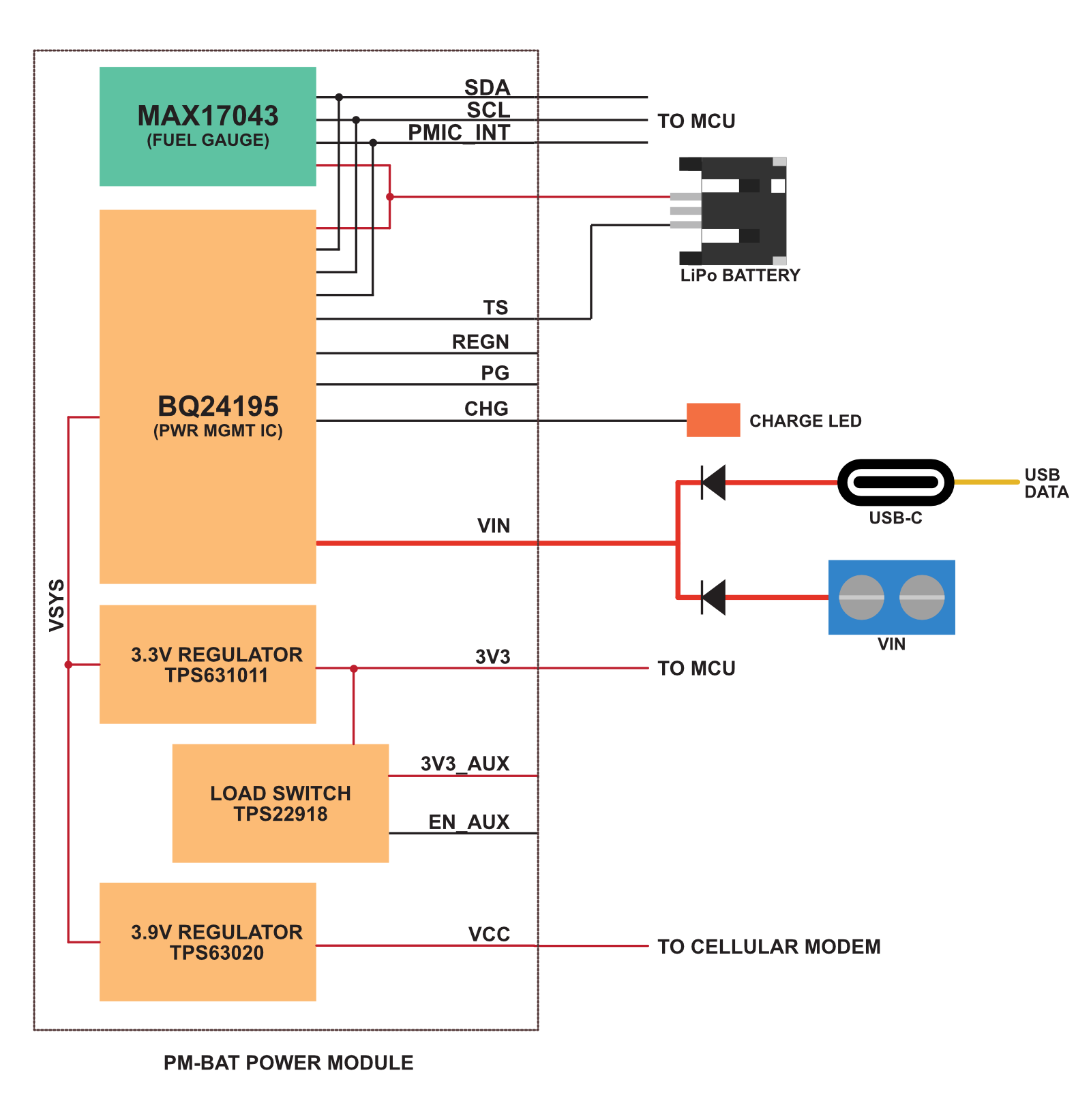
The Particle PM-BAT power module is a small module that contains:
- 5V to 17VDC input
- 3.3V regulated output for MCU (2A)
- 3.9V output for cellular modem (2A)
- bq24195 PMIC (power management and charge controller)
- MAX17043 fuel gauge (LiPo battery charge sensor)
It can either be:
- A castellated module intended to be reflow soldered to your M.2 SoM base board
- A module with male pins on the bottom that can be plugged into a socket on your M.2 SoM base board
The PM-DC power module is also available if you do not need battery support and want to power from an external DC source.
Block diagram
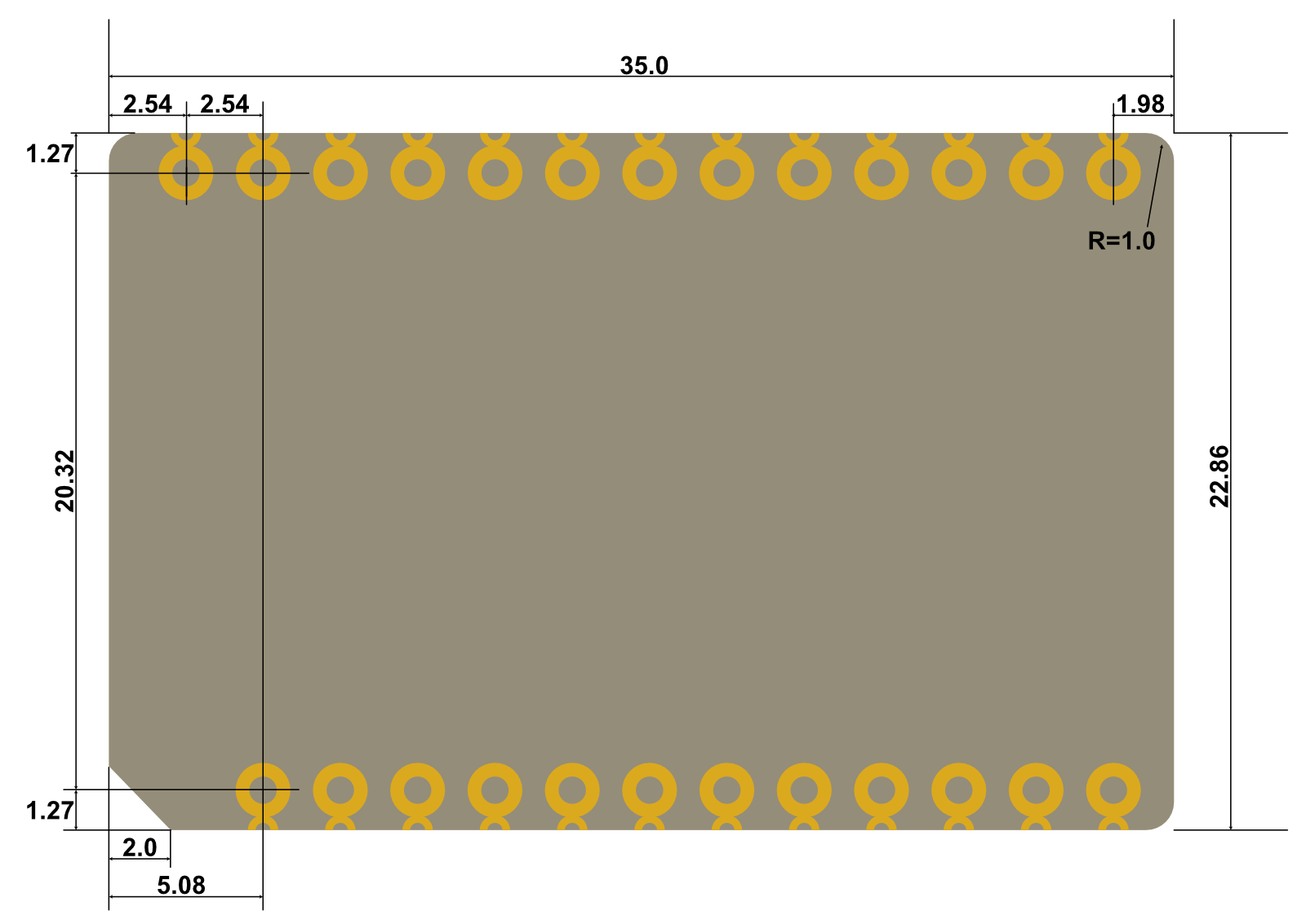
Dimensions
Dimensions in mm
- Module is 35mm x 22.86mm (1.38" x 0.9")
- Pins and castellated holes are 2.54mm (0.1") apart
For the castellated module: 4.7mm from the bottom of the circuit board to the top of the shield for the castellated module.
For the pin header module: 7.1mm from the bottom of the plastic strip for the pin header module. This is basically the distance from board to the top of the module if you use a bottom-mount socket like the M.2 breakout board. If you use a top mount socket of course you'd also need to add the height your header.
Pinout

| Pin | Pin Name | Description |
|---|---|---|
| 1 | 3V3 | Power output 3.3V |
| 2 | 3V3_AUX | Power output 3.3V, controllable |
| 3 | 5V | Power output 5V (not available on this module) |
| 4 | 5V | Power output 5V (not available on this module) |
| 5 | VCC | Power output 3.9V 2A for cellular modem |
| 6 | VCC | Power output 3.9V 2A for cellular modem |
| 7 | EN_AUX | Enable 33_AUX (has 100K pull-down to default off) |
| 8 | REGN | PMIC REGN output used for temperature sensor |
| 9 | GND | Ground |
| 10 | GND | Ground |
| 11 | VIN | Power in 5V - 17V |
| 12 | VIN | Power in 5V - 17V |
| 13 | CHG | Charge indicator output |
| 14 | SCL | I2C SCL. No internal pull on power module. |
| 15 | SDA | I2C SDA. No internal pull on power module. |
| 16 | /FUEL_INT | PMIC and FUEL_INT interrupt output open drain. Connect to M.2 SoM pin 45 (A6) for both B-SoM and M-SoM. |
| 17 | TS | LiPo battery temperature sensor (NTC thermistor) |
| 18 | VBAT | LiPo battery connection 3.7V |
| 19 | VBAT | LiPo battery connection 3.7V |
| 20 | VBAT | LiPo battery connection 3.7V |
| 21 | GND | Ground |
| 22 | GND | Ground |
| 23 | /RST | MCU reset button, active low. |
| 24 | PG | Power good output. Open drain, is pulled low on failure of either regulator. |
| 25 | ENABLE | Power output enable. Has internal pull-up to VSYS, pull to GND to disable power outputs. |
3V3_AUX is powered by 3V3 via a load switch (TPS22918). It can supply up to the full 2A of 3V3. It defaults to off due to a pull-down resistor on the pin. Pull to 3V3 to enable the 3V3_AUX output.
The I2C connection is required; the module will not operate correctly without configuration by I2C to adjust the input current limit and other settings.
The /FUEL_INT is an open-drain output that goes low if the PMIC or fuel gauge chip signals an interrupt
condition. This should be connected to M.2 SoM pin 45 (A6) for both B-SoM and M-SoM. On the M-SoM, pin A6
pin cannot wake the M-SoM from hibernate sleep mode, but can wake from stop or ULP sleep modes.
Firmware settings
Devices using the Particle Power Module include a 3V3_AUX power output
that can be controlled by a GPIO. On the M.2 SoM breakout board, this powers the Feather connector. On the Muon,
it powers the Ethernet port, LoRaWAN module, 40-pin expansion HAT connector, and QWIIC connector.
The main reason for this is that until the PMIC is configured, the input current with no battery
connected is limited to 100 mA. This is insufficient for the M-SoM to boot when
using a peripheral that requires a lot of current, like the WIZnet W5500 Ethernet module. The
system power manager prevents turning on 3V3_AUX until after the PMIC is configured
and the PMIC has negotiated a higher current from the USB host (if powered by USB).
This setting is persistent and only needs to be set once. In fact, the PMIC initialization
normally occurs before user firmware is run. This is also necessary because if you are using Ethernet
and enter safe mode (breathing magenta), it's necessary to enable 3V3_AUX so if you are using
Ethernet, you can still get OTA updates while in safe mode.
After changing the auxiliary power configuration you must reset the device.
The following code can be used to enable Ethernet on the M.2 SoM breakout board. This only needs to be done once and the device must be reset after configuration for the changes to take effect. It requires Device OS 5.9.0 or later.
// Enable 3V3_AUX
SystemPowerConfiguration powerConfig = System.getPowerConfiguration();
powerConfig.auxiliaryPowerControlPin(D23).interruptPin(A6);
System.setPowerConfiguration(powerConfig);

// Enable Ethernet
if_wiznet_pin_remap remap = {};
remap.base.type = IF_WIZNET_DRIVER_SPECIFIC_PIN_REMAP;

System.enableFeature(FEATURE_ETHERNET_DETECTION);
remap.cs_pin = D5;
remap.reset_pin = PIN_INVALID;
remap.int_pin = PIN_INVALID;
auto ret = if_request(nullptr, IF_REQ_DRIVER_SPECIFIC, &remap, sizeof(remap), nullptr);
Land pattern (SMD)
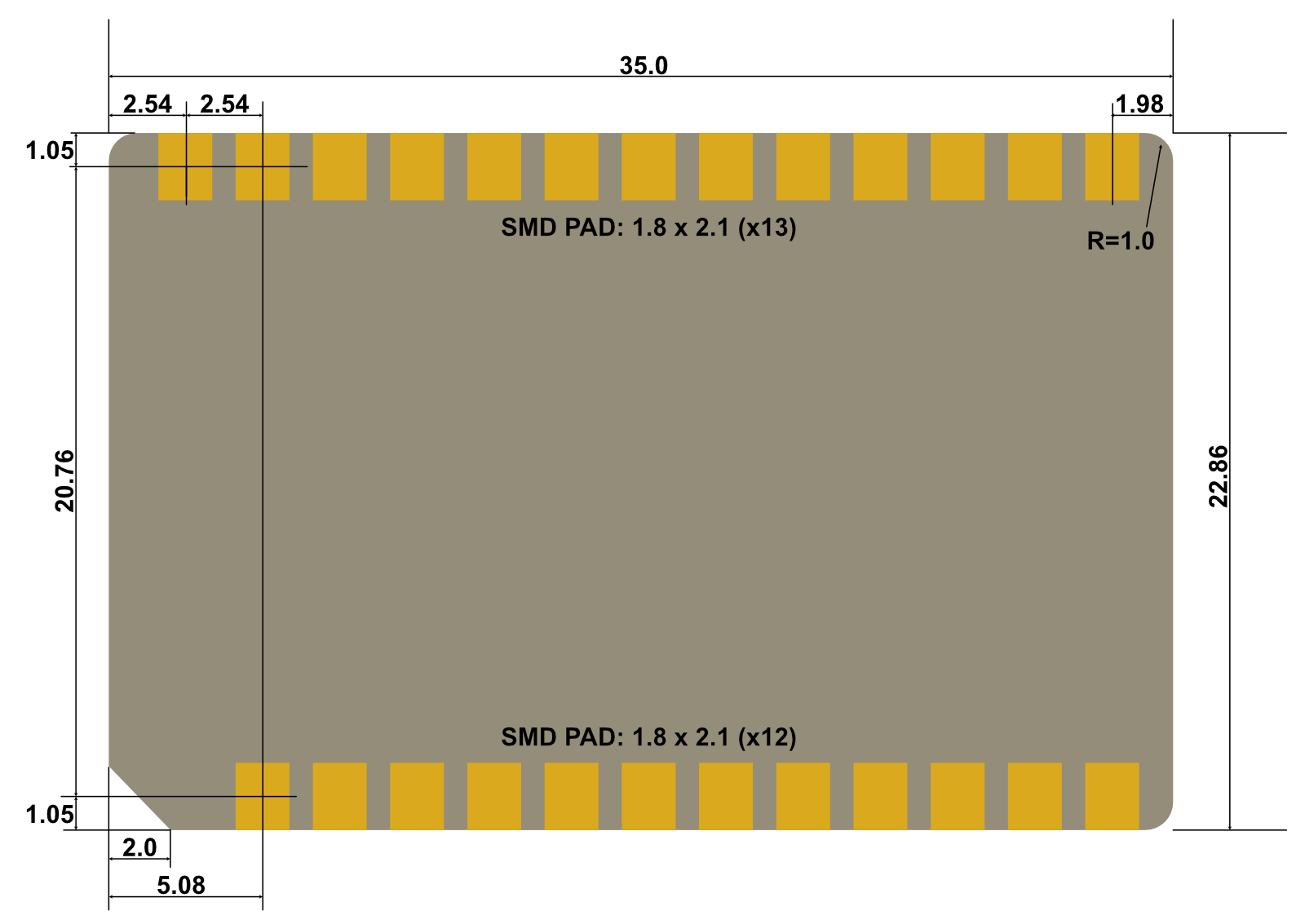
Dimensions in mm
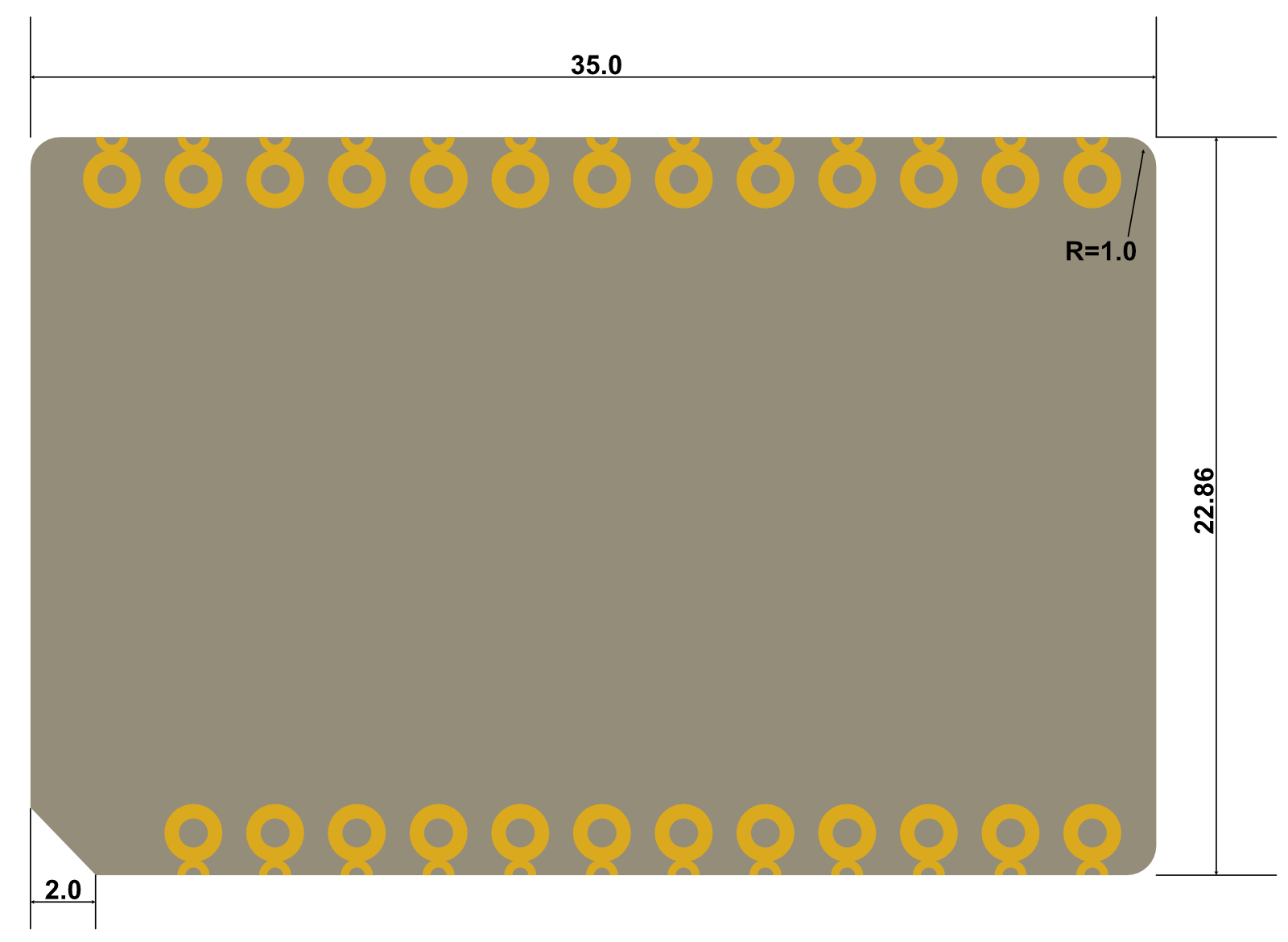
Pin layout
Dimensions in mm
- Male header pins are 0.1" spacing, 12 or 13 pins per side
- Two rows, spaced 0.8" (20.32mm) apart
The mating header is available from a large number of suppliers in both PTH and SMD styles.
| Style | Manufacturer | Model | Example |
|---|---|---|---|
| PTH (12) | Sullins | PPTC121LFBN-RC | Digikey |
| PTH (13) | Sullins | PPTC131LFBN-RC | Digikey |
| SMD (12) | Sullins | NPTC121KFXC-RC | Digikey |
| SMD (13) | Sullins | NPTC131KFXC-RC | Digikey |
The bottom-mount headers used on the M.2 Breakout Board will be difficult to source. The parts used are:
- Kaweei CP25411-13G-S116-A
- Kaweei CP25411-12G-S116-A
Schematic

Battery temperature sensor
The power module PM-BAT can work with or without a battery temperature sensor.
Without a temperature sensor
Leave the power module TS pin unconnected. Charging will always be enabled in hardware, but you can still control charging in software if you wish to do so.
With a temperature sensor
Connect the power module TS pin to a voltage divider as shown here:
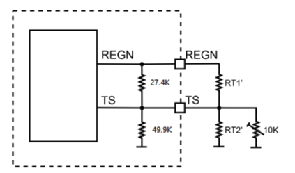
The values for your resistors can be used to control the charge temperature range using the calculator tool below.
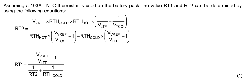
Calculator
When calculating based on resistance, this formula from the bq24195 datasheet is used:
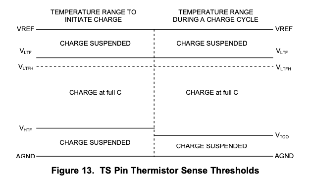
This graph shows the relationship between VLTF, VHTF, and VTCO. Note that since the thermistor is NTC (negative temperature coefficient), higher voltages indicate lower temperatures.
Ordering information
| SKU | Description | Lifecycle |
|---|---|---|
| PMBATH1EA | Particle Power Module, Battery, with Header [x1] | GA |
| PMBATH1EA | Particle Power Module, Battery, with Header | In development |
| PMBATH1TY | Particle Power Module, Battery, with Header [x50] | GA |
| PMBATNH1EA | Particle Power Module, Battery, No Header | In development |
| PMBATNH1TY | Particle Power Module, Battery, without Header [x50] | GA |
Version history
| Revision | Date | Author | Comments |
|---|---|---|---|
| pre | 2024-02-27 | RK | Initial version |
| 2024-02-28 | RK | Added plug-in version | |
| 2024-03-12 | RK | Updated to v2, dimensions changed | |
| 2024-04-08 | RK | Updated to v4, pin changes | |
| 2024-04-15 | RK | Corrected the /FUEL_INT pin description | |
| 001 | 2024-06-27 | RK | Initial version |
| 002 | 2024-09-18 | RK | Add firmware settings |
| 003 | 2025-11-01 | RK | Added height |