
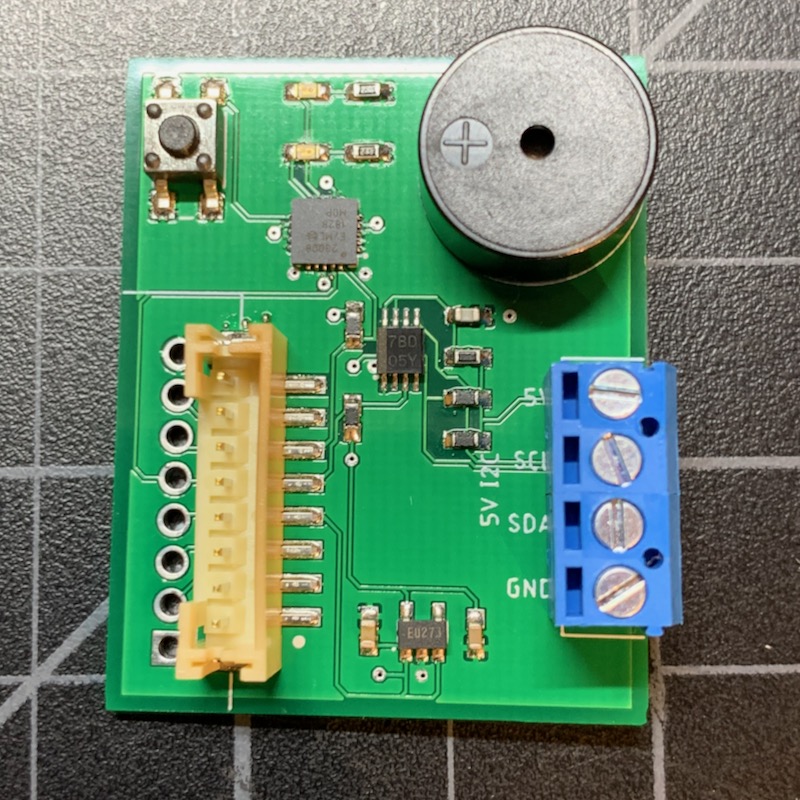
Tracker button and LEDs
This application note shows how to connect add a push button, two LEDs, a buzzer, and a 5V I2C port for the SHT30 temperature and humidity sensor to the Tracker One using the M8 connector.
You can download the files associated with this app note as a zip file.
Introduction
This application note illustrates several hardware and software techniques:
- Expanding the Tracker One using the M8 connector
- Adding a MCP23008 to add 8 GPIO
- Adding and debouncing a button via the MCP23008 GPIO expander
- Adding LED indicators via the MCP23008 GPIO expander
- Adding a small buzzer via the MCP23008 GPIO expander
- Interfacing with 5V I2C devices such as the SHT30 temperature and humidity sensor
The Tracker One M8 connector only has three available pins for GPIO, and two of them are shared with serial and I2C. By using an external MCP23008 I2C GPIO interface, you can add many more GPIO pins.
Connecting
The M8 (8mm) 8-pin connector on the Tracker One is standard, however it's not common. Some other connectors like M12 are more common, however, the 12mm connector would have required a taller enclosure to fit the larger connector. To simplify designs, Particle will provide a M8 female-to-wires cable, similar to this. This is for illustration only and the design may vary in the future.
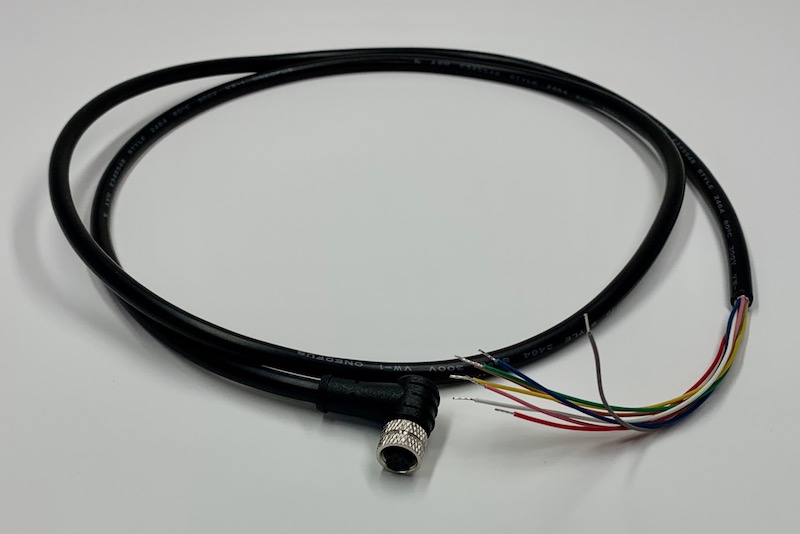
The common use case will be to include a cable gland in your expansion enclosure, pass the wires through the gland, and terminate them on your custom expansion board.
You'd typically connect those wires to your custom expansion board using one of several methods:
- Terminate with pins in a PHR-8 to mate with a B8B-PH on your expansion board
- Terminate with screw terminals on your board
- Terminate by soldering the wires to your board
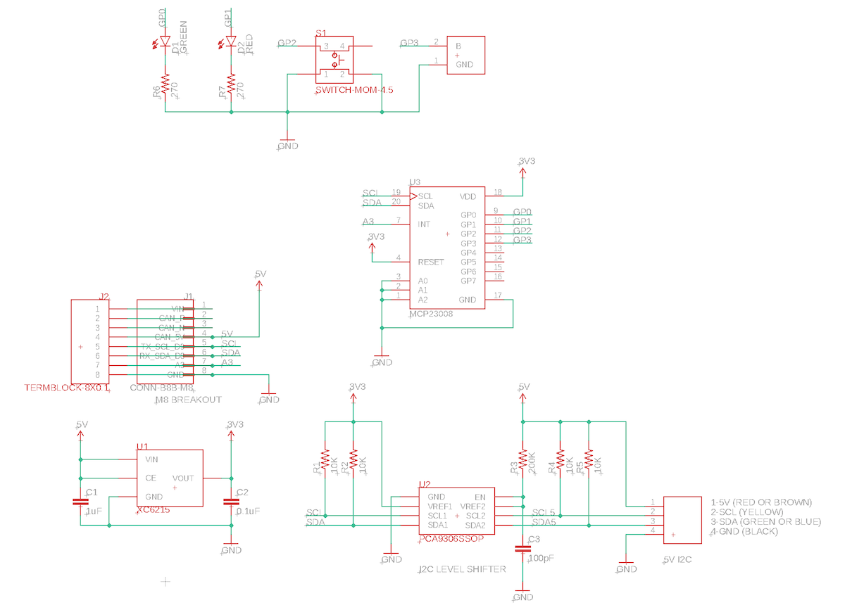
Hardware design
Full design
Schematic:
Board Layout:
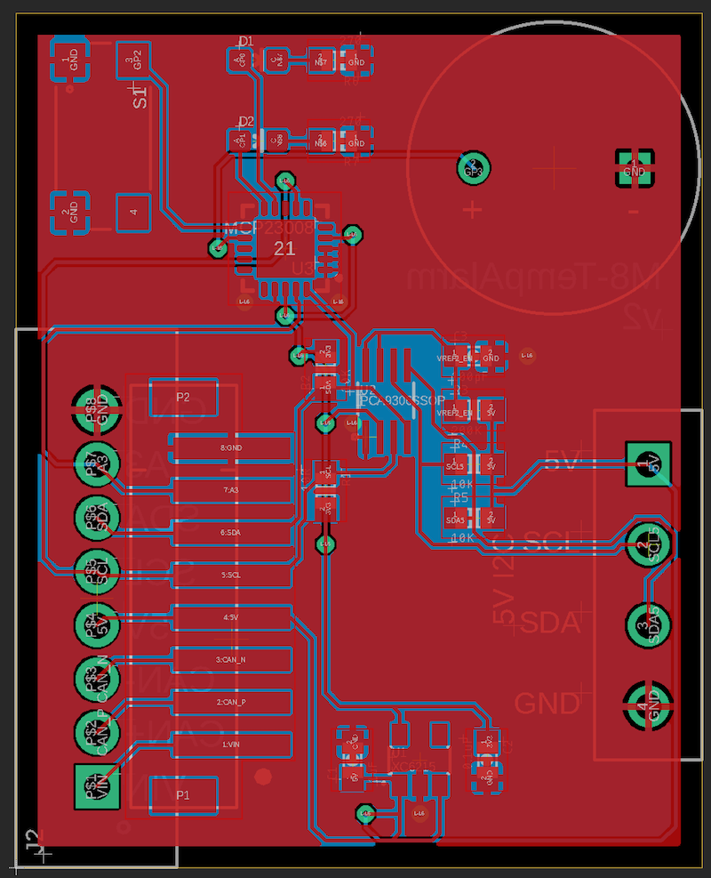
The Eagle CAD files for this design and the Gerber files are included in the eagle subdirectory.
BoM (Bill of Materials) -
| Quantity | Part | Description | Example | Cost |
|---|---|---|---|---|
| 1 | C1 | CAP CER 1UF 25V X7R 0603 | Samsung CL10B105KA8NNNC | |
| 1 | C2 | CAP CER 0.1UF 25V X7R 0603 | Samsung CL10B104KA8NNNC | |
| 1 | C3 | CAP CER 100pF 50V 0603 | Kemet C0603C101J5GACTU | |
| 1 | D1 | LED GREEN CLEAR 0603 SMD | Lite-On LTST-C193KGKT-5A | $0.41 |
| 1 | D2 | LED RED CLEAR 0603 SMD | Lite-On LTST-C193KRKT-5A | $0.41 |
| 4 | R1, R2, R4, R5 | RES 10K 5% 1/4W 0603 | Panasonic ERJ-PA3J103V | |
| 1 | R3 | RES 200K 1% 1/10W 0603 | Panasonic ERJ-3EKF2003V | |
| 2 | R6, R7 | RES SMD 270 OHM 5% 1/10W 0603 | Panasonic ERJ-3GEYJ271V | |
| 1 | S1 | SWITCH TACTILE SPST-NO 50MA 12V | E-Switch TL3305AF160QG | $0.20 |
| 1 | U1 | IC REG LINEAR 3.3V 200MA SOT25 | Torex XC6215B332MR-G | $0.71 |
| 1 | U2 | PCA9306 I2C LEVEL SHIFTER | TI PCA9306SSOP | $0.67 |
| 1 | U3 | IC I/O EXPANDER I2C QFN-20 | Microchip MCP23008T-E/ML | $1.10 |
| 1 | U$1 | TERM BLK 4POS SIDE ENT 3.5MM PCB | On Shore OSTTE040161 | $1.01 |
| 1 | U$2 | Buzzer | CUI Devices CPI-1375-80T | $1.39 |
Choose one of:
| Quantity | Part | Description | Example | Cost |
|---|---|---|---|---|
| 1 | J1 | Conn SMD 8 position 2.00mm | JST B8B-PH-SM4-TB(LF)(SN) | $1.00 |
| J2 | Male Header Pins (8x0.1") | Sullins PRPC040SAAN-RC | ||
| 1 | J2 | Screw Terminal Block 8x0.1" PTH | On Shore OSTVN08A150 | $2.36 |
LEDs, switch, and buzzer
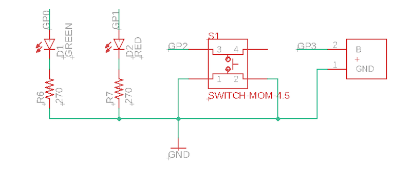
These are the input and output devices connected to the MCP23008 GPIO expander.
There are two SMD LEDs, one green and one red, connected high side to GP0 and GP1.
There's a momentary push-button switch for input. It connects the GP2 pin to GND, and takes advantage of the built-in pull-up resistor available on the MCP23008.
The buzzer is connected to GP3. In practice, this is more of a gentle chime than a warning buzzer, as it's connected to a 3.3V GPIO. A higher voltage is required to get the full volume output. One easy improvement would be to power the buzzer from CAN_5V and use an N-channel MOSFET (2N7002) low-side connected to GP3.
MCP23008
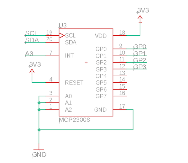
The MCP23008 is the I2C to GPIO interface chip. It can be run at 3.3V or 5V. This design uses the smaller 20-QFN-EP package running at 3.3V. There is a larger 18-SOIC version that may be easier to solder in the Tracker GPIO application note.
PCA9306
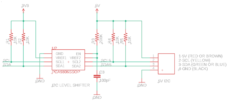
This example is designed to connect to a SHT30 temperature and humidity sensor, which requires a 5V power supply and 5V I2C logic.
The nRF52 is not 5V tolerant! You cannot directly connect 5V I2C to it!
To get around this issue, we use a PCA9306 I2C level-shifter. This converts between 3.3V and 5V logic. Note that I2C is bi-directional on both pins (SDA and SCL), so you can't just use a simple level-shifter.
Note that I2C requires pull-up resistors, and this design includes two sets, one to 3.3V and one to 5V, on either side of the PCA9306.
More information on using the SHT30 temperature and humidity sensor can be found in AN022 Tracker SHT3x Temperature/Humidity.
Regulator and M8 connector
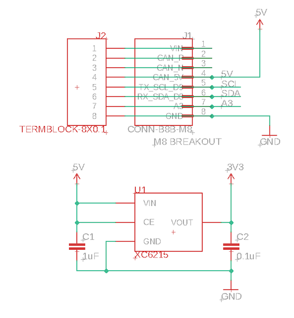
The M8 connector supplies 5V at 370 mA, and can be turned on and off using the CAN_PWR GPIO. There is a boost converter on the Tracker SoM and 5V is available off battery as well as USB and external VIN power.
Since the nRF52840 MCU only supports 3.3V logic levels on I2C, Serial, and GPIO, a 3.3V regulator is often required. This design uses a Torex XC6215. It's tiny, inexpensive ($0.71), and does not require an external inductor, which saves space and BoM costs. It's a 200 mA linear regulator, but the voltage from from CAN_5V to 3.3V is small enough and the load low enough that this is a reasonable choice.
Test software
This board will be used in a more full-featured example later. However this is test firmware to test the functionality of the board.
Tapping the button will cycle between green, red, green + red, and LEDs off.
Holding down the button for 4 seconds will toggle the buzzer on and off.
Libraries
The following libraries are used:
| Library | Version | GitHub | |
|---|---|---|---|
| MCP23008-RK | 0.0.4 | https://github.com/rickkas7/MCP23008-RK | |
| DebounceSwitchRK | 0.0.1 | https://github.com/rickkas7/DebounceSwitchRK | |
| sht3x-i2c | 1.0.0 | https://github.com/particle-iot/sht3x-i2c |
If using Particle workbench, you can use this project.properties file:
dependencies.MCP23008-RK=0.0.4
dependencies.DebounceSwitchRK=0.0.1
dependencies.sht3x-i2c=1.0.0
Firmware
#include "Particle.h"

#include "DebounceSwitchRK.h"
#include "MCP23008-RK.h"
#include "sht3x-i2c.h"

#ifndef SYSTEM_VERSION_v620
SYSTEM_THREAD(ENABLED); // System thread defaults to on in 6.2.0 and later and this line is not required
#endif

SerialLogHandler logHandler;

MCP23008 gpio(Wire3, 0x20);

Sht3xi2c sensor(Wire3, 0x44);

pin_t GPIO_INT_PIN = A3;

uint16_t GREEN_PIN = 0;
uint16_t RED_PIN = 1;
uint16_t SWITCH_PIN = 2; // GP2
uint16_t BUZZER_PIN = 3;

int ledState = 0;
bool buzzerState = 0;

const unsigned long printTempMs = 5000;
unsigned long lastPrintTemp = 0;

void setup() {
    waitFor(Serial.isConnected, 15000);

    DebounceSwitch::getInstance()->setup();

    // Turn on power on Tracker CAN_5V
    pinMode(CAN_PWR, OUTPUT);
    digitalWrite(CAN_PWR, HIGH);
    delay(200);

    sensor.begin(CLOCK_SPEED_400KHZ);
    sensor.start_periodic();

    // Initialize MCP23008
    gpio.begin();

    // When using interrupt mode, you need to assocate a physical MCU pin as an interrupt pin
    // from the MCP23008 INT output
    gpio.enableInterrupts(GPIO_INT_PIN, MCP23008InterruptOutputType::OPEN_DRAIN);

    gpio.pinMode(GREEN_PIN, OUTPUT);
    gpio.digitalWrite(GREEN_PIN, LOW);

    gpio.pinMode(RED_PIN, OUTPUT);
    gpio.digitalWrite(RED_PIN, LOW);

    gpio.pinMode(SWITCH_PIN, INPUT_PULLUP);

    gpio.pinMode(BUZZER_PIN, OUTPUT);
    gpio.digitalWrite(BUZZER_PIN, LOW);

    // Disable very long press mode
    DebounceSwitch::getInstance()->withNoVeryLongPress();

    DebounceSwitchState *sw = DebounceSwitch::getInstance()->addSwitch(
        DebounceSwitch::NOTIFY_PIN, DebounceSwitchStyle::PRESS_LOW,
        [](DebounceSwitchState *switchState, void *) {
            // Called to notify of switch operations
            Log.info("state=%s", switchState->getPressStateName());
            if (switchState->getPressState() == DebouncePressState::TAP) {
                ledState++;
                if (ledState >= 4) {
                    ledState = 0;
                }
                gpio.digitalWrite(GREEN_PIN, (ledState & 0b01) != 0);
                gpio.digitalWrite(RED_PIN, (ledState & 0b10) != 0);
            }
            else
            if (switchState->getPressState() == DebouncePressState::LONG) {
                buzzerState = !buzzerState;
                gpio.digitalWrite(BUZZER_PIN, buzzerState);
            }
        }, NULL);

    gpio.attachInterrupt(SWITCH_PIN, CHANGE,
        [sw](bool bValue) {
        // This code runs in a worker thread with a 1024 byte stack, so avoid doing
        // anything that requires a long time or stack here.
        // Log.info("bValue=%d", bValue);
        sw->notify(bValue);
    });

}


void loop() {
    if (millis() - lastPrintTemp >= printTempMs) {
        lastPrintTemp = millis();

        double temp, humid;

        int err = sensor.get_reading(&temp, &humid);
        if (err == 0)
        {
            Log.info("temp=%.2lf hum=%.2lf", temp, humid);
        }
        else {
            Log.info("no sensor err=%d", err);
        }
    }

}