
Tracker GPIO
You can download the files associated with this app note as a zip file.
Introduction
This application note illustrates several hardware and software techniques:
- Expanding the Tracker One using the M8 connector.
- Interfacing with 5V I2C devices (optional).
- Adding a MCP23008 to add 8 GPIO. Can be configured as 3.3V or 5V GPIO at board assembly time.
The Tracker One M8 connector only has three available pins for GPIO, and two of them are shared with serial and I2C. By using an external MCP23008 I2C GPIO interface, you can add many more GPIO pins.
The nRF52840 MCU GPIO is 3.3V only, and is not 5V tolerant. You can use the techniques in this application note to interface with 5V GPIO with true 5V logic levels.
The MCP23008 allows the pins to be configured for input, input pull-up, or output. In input mode the pins are high-impedance (Hi-Z) so you can use that to implement open-collector style output as well.
If you need even more GPIO you can add an MCP23017 (16 GPIO), and even add more than one, if necessary.
AN027 Tracker Button and LEDs shows how to connect add a push button, two LEDs, a buzzer, and a 5V I2C port for the SHT30 temperature and humidity sensor to the Tracker One using the M8 connector.
Connecting
The M8 (8mm) 8-pin connector on the Tracker One is standard, however it's not common. Some other connectors like M12 are more common, however, the 12mm connector would have required a taller enclosure to fit the larger connector. To simplify designs, Particle will provide a M8 female-to-wires cable, similar to this. This is for illustration only and the design may vary in the future.
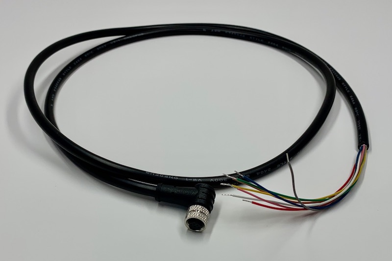
The common use case will be to include a cable gland in your expansion enclosure, pass the wires through the gland, and terminate them on your custom expansion board.
You'd typically connect those wires to your custom expansion board using one of several methods:
- Terminate with pins in a PHR-8 to mate with a B8B-PH on your expansion board
- Terminate with screw terminals on your board
- Terminate by soldering the wires to your board
This example design is intended to be a prototype for illustration purposes only. It includes the same B8B-PH connector that is inside the Tracker One on the Tracker Carrier board. This connector is inexpensive and can be attached to the Tracker One Carrier Board.
Hardware design
Full design
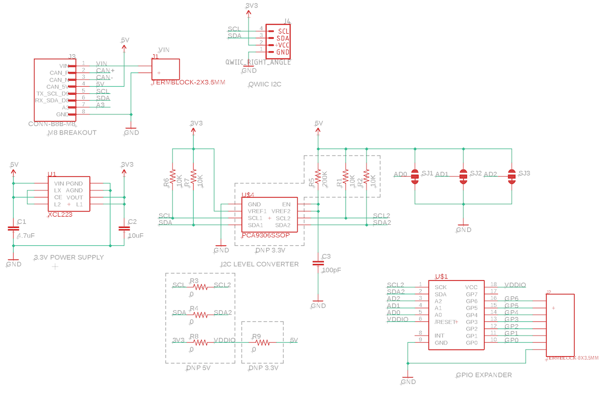
Schematic:
Board:
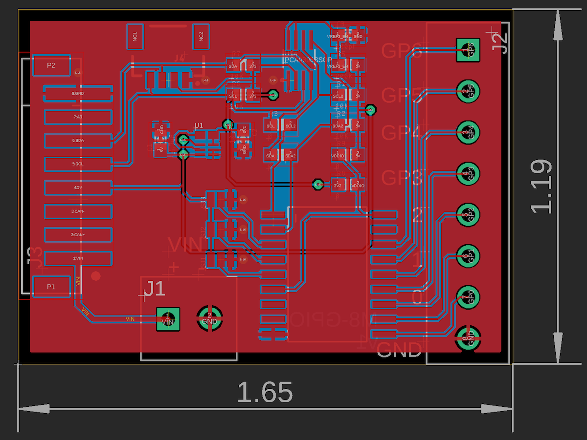
The Eagle CAD files for this design and the Gerber files are included in the eagle subdirectory.
BoM (Bill of Materials) - 5V GPIO
| Quantity | Part | Description | Example | Cost |
|---|---|---|---|---|
| 1 | C1 | Capacitor Ceramic 4.7uF 6.3V 0603 | Murata GRM188R60J475KE19J | |
| 1 | C2 | Capacitor Ceramic 10uF 16V 0805 | Murata GRM21BR61C106KE15L | |
| 1 | C3 | Capacitor Ceramic 100pF 50V 0603 | Kemet C0603C101J5GACTU | |
| 1 | R9 | Resistor 0-ohm 0603 | Panasonic ERJ-3GEY0R00V | |
| 4 | R1, R2, R6, R7 | Resistor 10K 5% 1/4W 0603 | Panasonic ERJ-PA3J103V | |
| 1 | R5 | Resistor 200K 1% 1/10W 0603 | Panasonic ERJ-3EKF2003V | |
| 1 | J3 | Conn SMD 8 position 2.00mm | JST B8B-PH-SM4-TB(LF)(SN) | $1.00 |
| 1 | U1 | XCL224 3.3V regulator | Torex XCL224A333D2-G | $ 2.43 |
| 1 | U$4 | PCA9306SSOP | TI | $0.67 |
| 1 | U$1 | IC I/O EXPANDER I2C 8B 18SOIC | MCP23008T-E/SO | $1.08 |
| 1 | J4 | QWIIC JST 4-pin 1mm (optional) | Sparkfun | $0.50 |
| 1 | J1 | TERMBLOCK-2X3.5MM (optional) | On Shore OSTTE020161 | $0.67 |
| 1 | J2 | TERM BLK 8POS SIDE ENT 3.5MM PCB | On Shore OSTTE080161 | $1.73 |
BoM (Bill of Materials) - 3.3V GPIO
| Quantity | Part | Description | Example | Cost |
|---|---|---|---|---|
| 1 | C1 | Capacitor Ceramic 4.7uF 6.3V 0603 | Murata GRM188R60J475KE19J | |
| 1 | C2 | Capacitor Ceramic 10uF 16V 0805 | Murata GRM21BR61C106KE15L | |
| 3 | R3, R4, R8 | Resistor 0-ohm 0603 | Panasonic ERJ-3GEY0R00V | |
| 2 | R1, R2 | Resistor 10K 5% 1/4W 0603 | Panasonic ERJ-PA3J103V | |
| 1 | J3 | Conn SMD 8 position 2.00mm | JST B8B-PH-SM4-TB(LF)(SN) | $1.00 |
| 1 | U1 | XCL224 3.3V regulator | Torex XCL224A333D2-G | $ 2.43 |
| 1 | U$1 | IC I/O EXPANDER I2C 8B 18SOIC | MCP23008T-E/SO | $1.08 |
| 1 | J4 | QWIIC JST 4-pin 1mm (optional) | Sparkfun | $0.50 |
| 1 | J1 | TERMBLOCK-2X3.5MM (optional) | On Shore OSTTE020161 | $0.67 |
| 1 | J2 | TERM BLK 8POS SIDE ENT 3.5MM PCB | On Shore OSTTE080161 | $1.73 |
Assembly (5V)
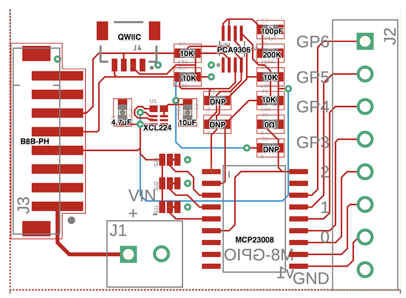
This board can be assembled as a 3.3V GPIO or 5V GPIO. When assembled as 5V:
- Populate U4 (PCA9306)
- Populate R1, R2, R5, R9
- DNP R3, R4, R8
Be careful with the DNP (do not populate) resistors. Populating both R8 and R9 will short 3V3 to 5V which may damage the XCL224 regulator, for example. Only one must be populated.
Assembly (3.3V)
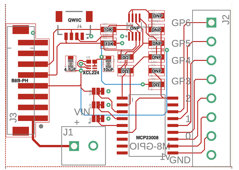
This board can be assembled as a 3.3V GPIO or 5V GPIO. When assembled as 3.3V:
- DNP U4 (PCA9306)
- DNP R1, R2, R5, R9
- Populate with a 0-ohm resistor R3, R4, R8
Be careful with the DNP (do not populate) resistors. Populating both R8 and R9 will short 3V3 to 5V which may damage the XCL224 regulator, for example. Only one must be populated.
Regulator
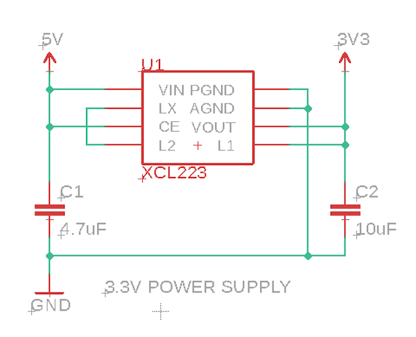
The M8 connector supplies 5V at 370 mA, and can be turned on and off using the CAN_PWR GPIO. There is a boost converter on the Tracker SoM and 5V is available off battery as well as USB and external VIN power.
Since the nRF52840 MCU only supports 3.3V logic levels on I2C, Serial, and GPIO, a 3.3V regulator is often required. This design uses a Torex XCL223 or XCL224. It's tiny, inexpensive, and does not require an external inductor, which saves space and BoM costs. It's a 700 mA regulator, but you'll be limited to the 370 mA on CAN_5V.
Note that even when running with 5V GPIO, a 3.3V regulator is still required to supply the 3V3 side of the PCA9306 I2C level shifter as the nRF52 requires 3.3V GPIO and I2C.
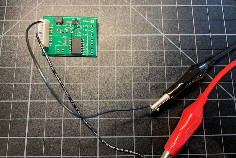
The XCL224 is tiny and is somewhat prone to solder bridges. When doing initial testing of the board I power by the B8B-PH connector using a bench supply so I can monitor the current easily.
PCA9306
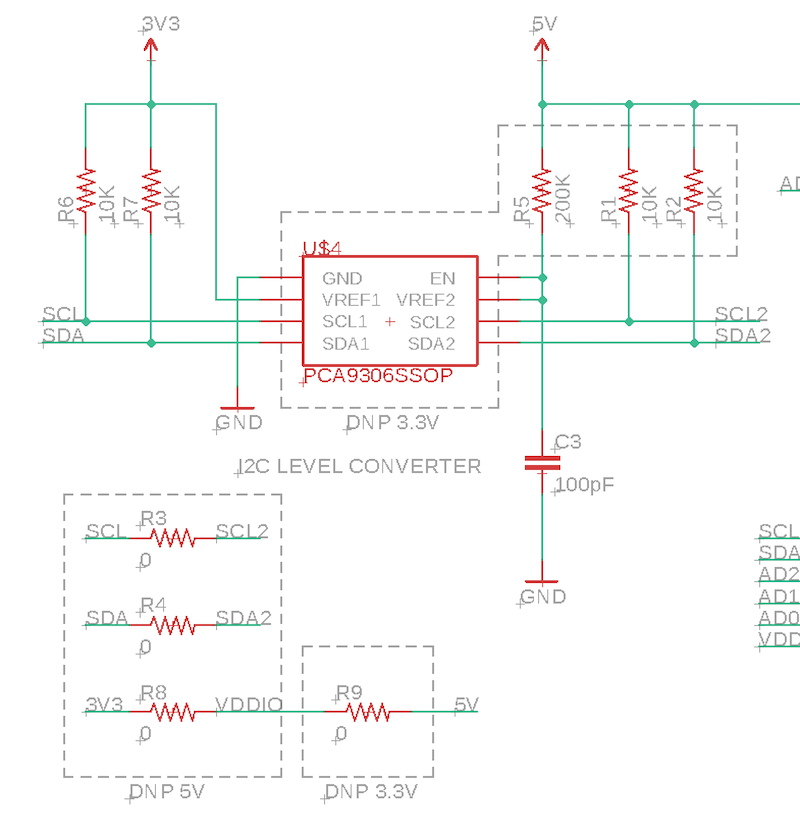
If we want to run the GPIO at 5V, this requires an I2C level shifter.
The nRF52 is not 5V tolerant! You cannot directly connect 5V I2C to it!
To get around this issue, we use a PCA9306 I2C level-shifter. This converts between 3.3V and 5V logic. Note that I2C is bi-directional on both pins (SDA and SCL), so you can't just use a simple level-shifter.
Note that I2C requires pull-up resistors, and this design includes two sets, one to 3.3V and one to 5V, on either side of the PCA9306.
When running the GPIO at 3.3V, the PCA9306 and some other components are omitted and three 0-ohm resistors are populated to connect the I2C busses without the PCA9306 and power the MCP23008 at 3.3V.
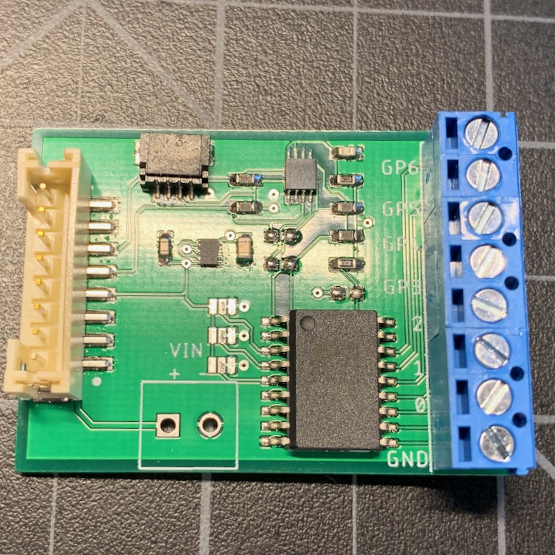
MCP23008
The MCP23008 is the I2C to GPIO interface chip. It can be run at 3.3V or 5V. The GPIO pins GP0-GP6 are connected to a screw terminal header, or can be soldered directly to leads.
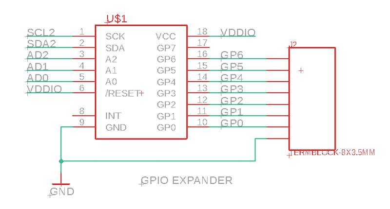
While this design uses the 18-SOIC version of the MCP23008, the AN018 Tracker Level uses the 20-QFN-EP package which is smaller. The capabilities and software are the same for both chips.
Qwiic Connector
This board includes a Sparkfun Qwiic connector. This allows other I2C devices to be easily chained off this board. This is handy for testing and prototyping, but is not necessary for a production device. You can find out how using Qwiic can make prototyping new sensor designs quick and easy on this page.
Firmware
Getting the Tracker Edge firmware
You can download a complete project for use with Particle Workbench as a zip file here:
Version:
- Extract tracker-an013.zip in your Downloads directory
- Open the tracker-an013 folder in Workbench using File - Open...; it is a pre-configured project directory.
- From the Command Palette (Command-Shift-P or Ctrl-Shift-P), use Particle: Configure Project for Device.
- If you are building in the cloud, you can use Particle: Cloud Flash or Particle: Cloud Compile.
- If you are building locally, open a CLI window using Particle: Launch CLI then:
particle library copy
Manually
The Tracker Edge firmware can be downloaded from GitHub:
https://github.com/particle-iot/tracker-edge
You will probably want to use the command line as there are additional commands you need to run after cloning the source:
git clone https://github.com/particle-iot/tracker-edge
cd tracker-edge
git submodule update --init --recursive
- Open Particle Workbench.
- From the command palette, Particle: Import Project.
- Run Particle: Configure Workspace for Device, select version 1.5.4-rc.1, 2.0.0-rc.3, or later, Tracker, and your device.
- Run Particle: Flash application (local).
Make sure you've used the Mark As Development Device option for your Tracker device in your Tracker product. If you don't mark the device as a development device it will be flashed with the default or locked product firmware version immediately after connecting to the cloud, overwriting the application you just flashed.
Add the MCP23008 library
From the command palette in Workbench, Particle: Install Library then enter MCP23008-RK.
The documentation for the library can be found here.
Customize main.cpp