
Monitor One Developer Edition
For additional technical details, see the Monitor One datasheet.
In the box
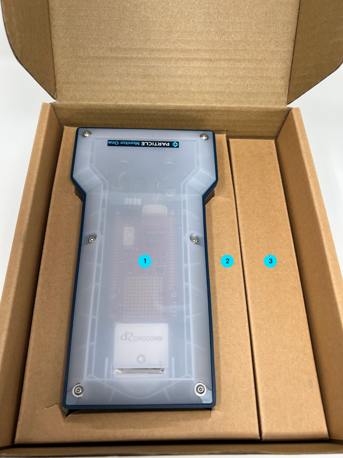
| Label | Feature |
|---|---|
| 1 | Monitor One |
| 2 | Accessories (bottom of box) |
| 3 | Power supply (inside side box) |
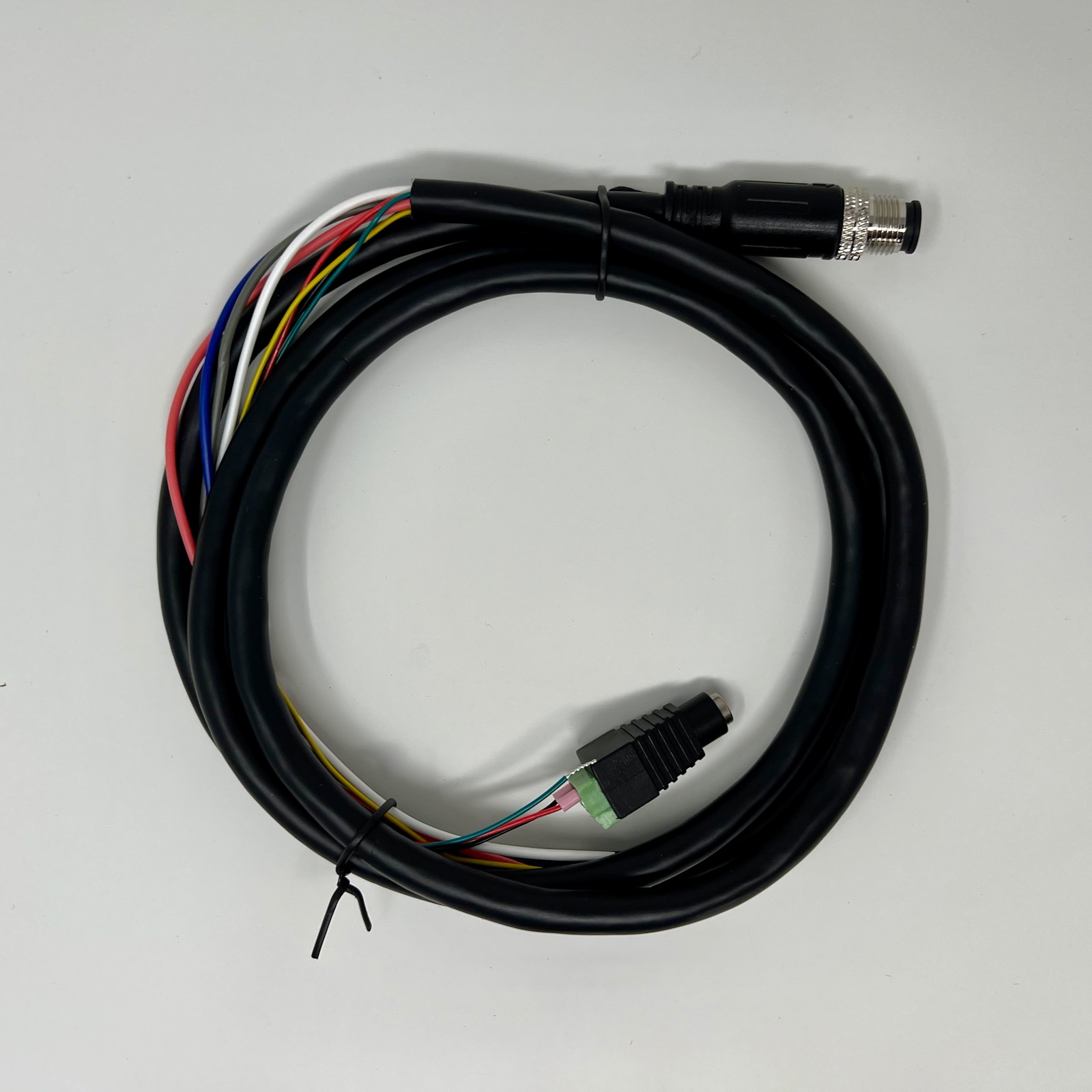
Cables
There are two cables in the box. The M12 8-pin in connector is used for power, and includes a barrel connector adapter.
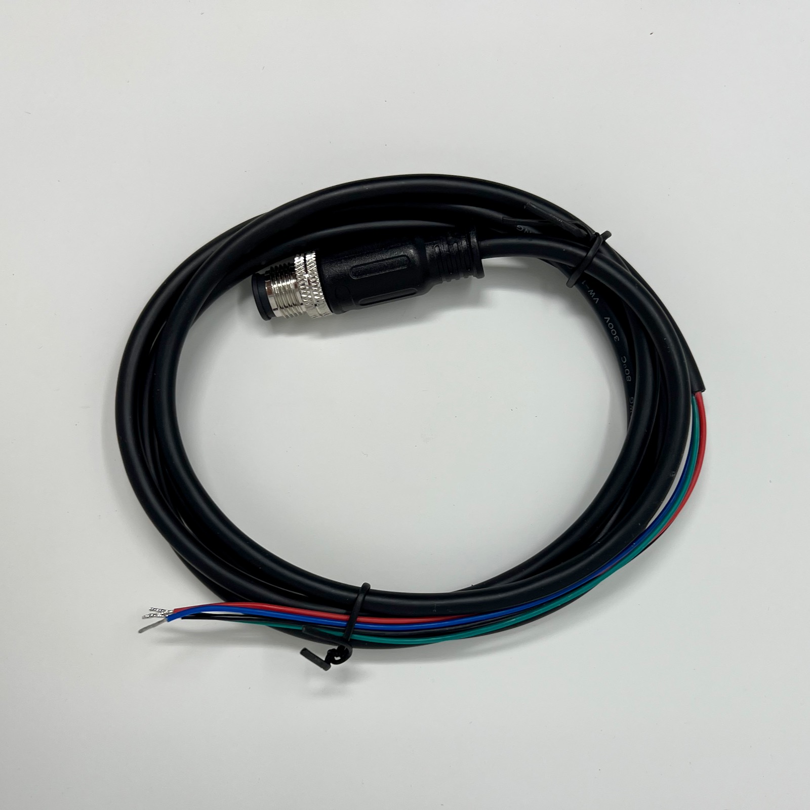
There is also an M12 4-pin connector for expansion. The I/O card uses this connector for the relay and the 0-10V opto-isolated digital input.
Power supply
The small rectangular box contains a power supply.
The DC output is 24 V DC at 1A (24W). The connector is a 5.5x2.1mm barrel plug, center positive.
USB and wrenches
One plastic bag contains a micro USB B cable and hex wrenches.
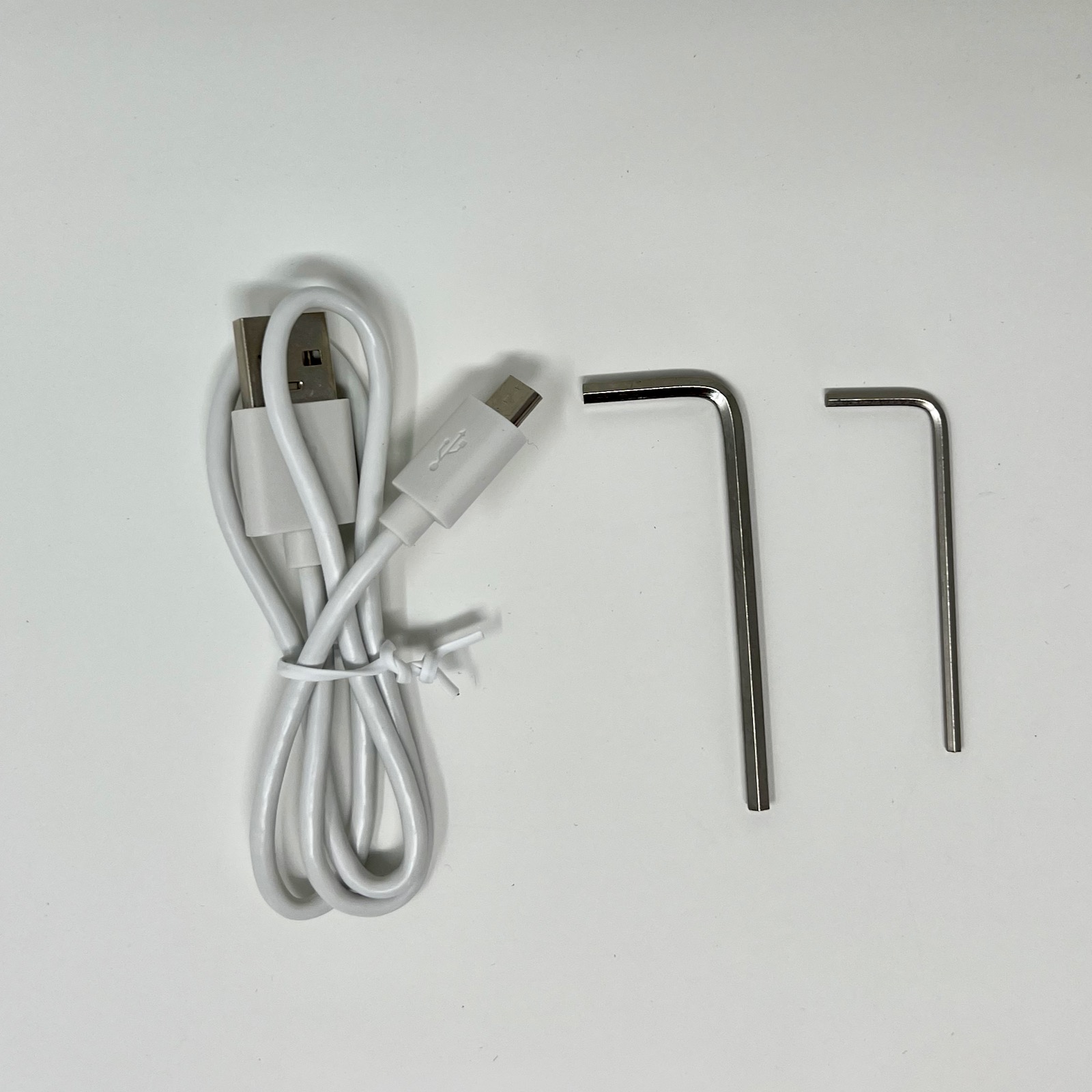
The USB connector is only available when the cover is removed. It is not externally accessible.
The hex wrenches include:
- M2 hex (2mm) for the cover screws
- M3 hex (3mm) for the mounting plate attachment screw
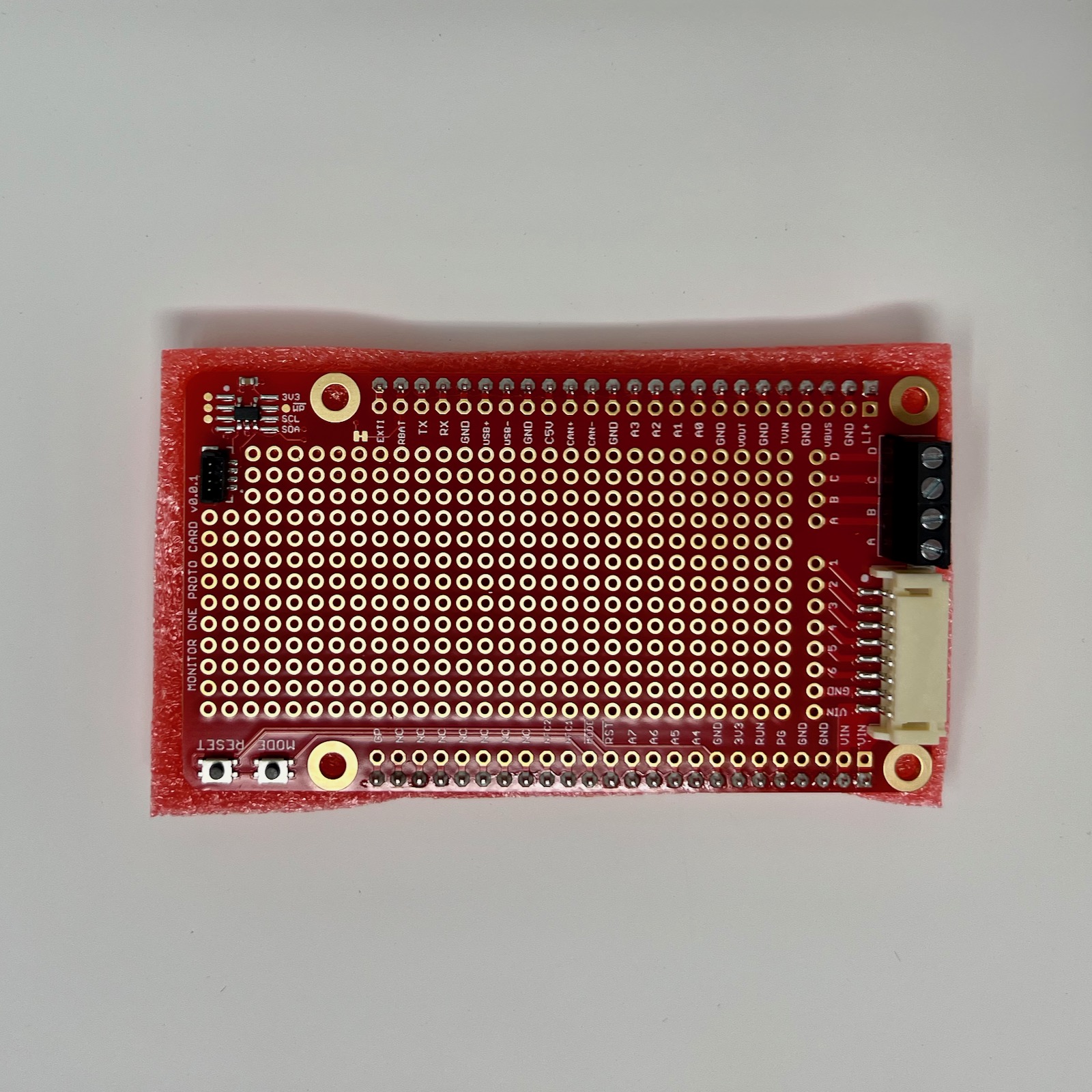
Prototype card
The prototype card can be used to design your own expansion card. It replaces the I/O card that is installed in the Monitor One if you choose to use it.
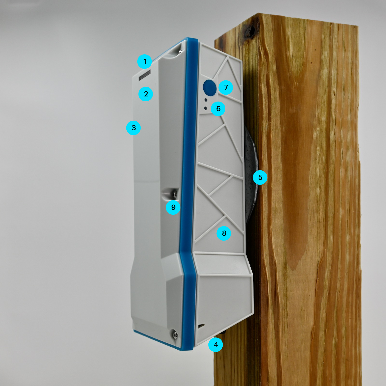
Monitor One external features
| Label | Feature |
|---|---|
| 1 | System RGB LED |
| 2 | GNSS antenna (internal) |
| 3 | Cellular antenna (internal) |
| 4 | External connectors (on bottom) |
| 5 | Magnetic, bolt-down, or strap-down mounting bracket |
| 6 | User RGB LEDs (2) |
| 7 | User button (externally accessible) |
| 8 | Wi-Fi geolocation antenna (internal) |
Connectors
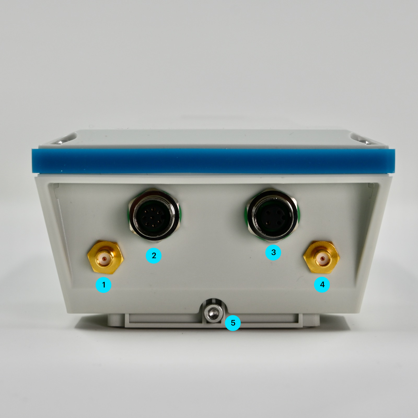
The bottom plate of the Monitor One can be customized with different connectors for your application.
| Label | Feature |
|---|---|
| 1 | Cellular antenna (SMA) |
| 2 | M12 connector (8-pin) |
| 3 | M12 connector (4-pin) |
| 4 | GNSS antenna (SMA) |
| 5 | Mounting plate attachment screw |
By default the Monitor One uses the internal cellular and GNSS antennas, but can be switched to using the external connectors inside the enclosure.
The cellular (1) and GNSS (4) antennas are not connected internally at the factory. In order to use the external connectors you must open the case, disconnect the internal antenna, and instead connect the U.FL connector for the external jack.
The Monitor One is equipped with 2 external-facing SMA bulkhead connectors for both cellular and GNSS but are disconnected internally. The hardware is ready for use with external antennas giving the ability to connect a wide variety of application-specific antennas. It is recommended that the user perform required RF certifications with the selected antenna installed as the Monitor One has only been certified for use in select regions with the internal antennas.
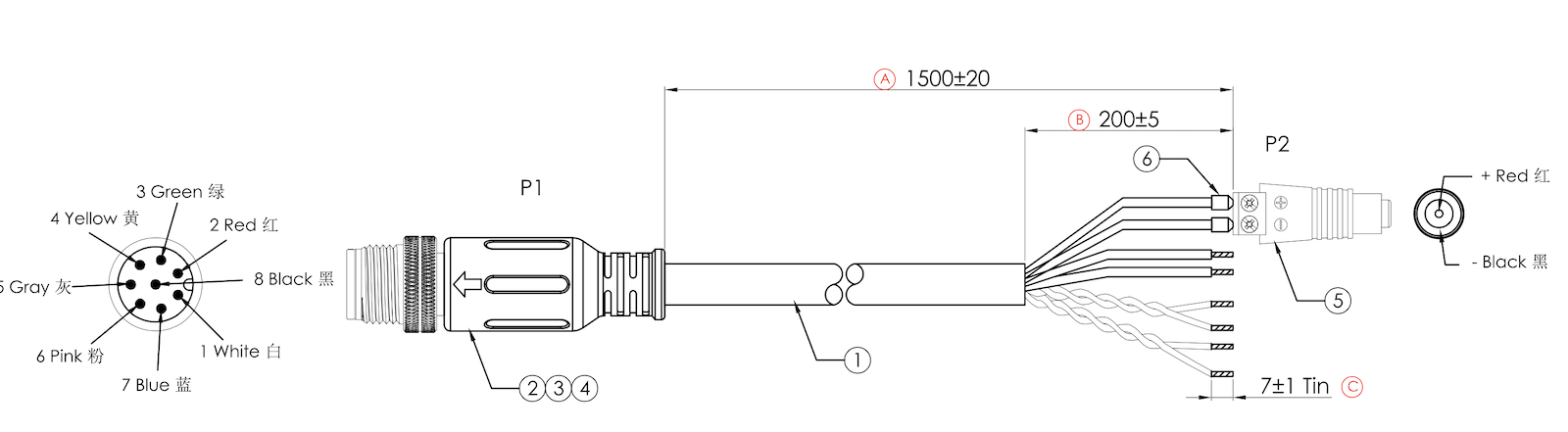
I/O expansion M12 8-pin to flying leads
The Monitor One includes a M12 8-pin male to flying leads cable, 1500±20mm (about 60 inches or 5 feet). This is used to power the Monitor One, and also use the 4-20mA, 0-10V analog in, CAN bus, and RS485 (Modbus) interfaces.
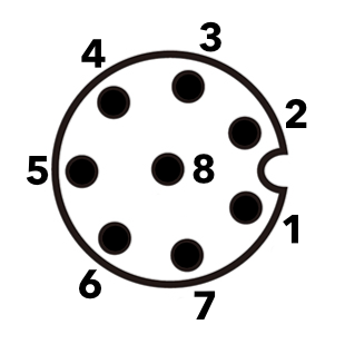
Looking at the pins on the end of the connector on the cable
| Conn P1 (M12) | Color | Function | GPIO |
|---|---|---|---|
| 1 | White | CAN_P | |
| 2 | Red | VIN (6-30 VDC) | |
| 3 | Green | 4-20mA input | A7 |
| 4 | Yellow | 0-10V input | A6 |
| 5 | Gray | RS485_B (N) | |
| 6 | Pink | RS485_A (P) | |
| 7 | Blue | CAN_N | |
| 8 | Black | Ground |
I/O expansion M12 4-pin to flying leads
The Monitor One includes a M12 4-pin male to flying leads cable, 1500±20mm (about 60 inches or 5 feet). You do not need to connect this cable initially.
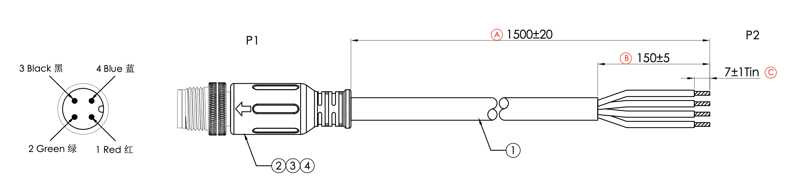
| Conn P1 (M12) | Color | Function | GPIO |
|---|---|---|---|
| 1 | Red | 12-24V slow-signal input | A5 |
| 2 | Green | Relay COM | |
| 3 | Black | Ground | |
| 4 | Blue | Relay (NO) | NFC_PIN2 |
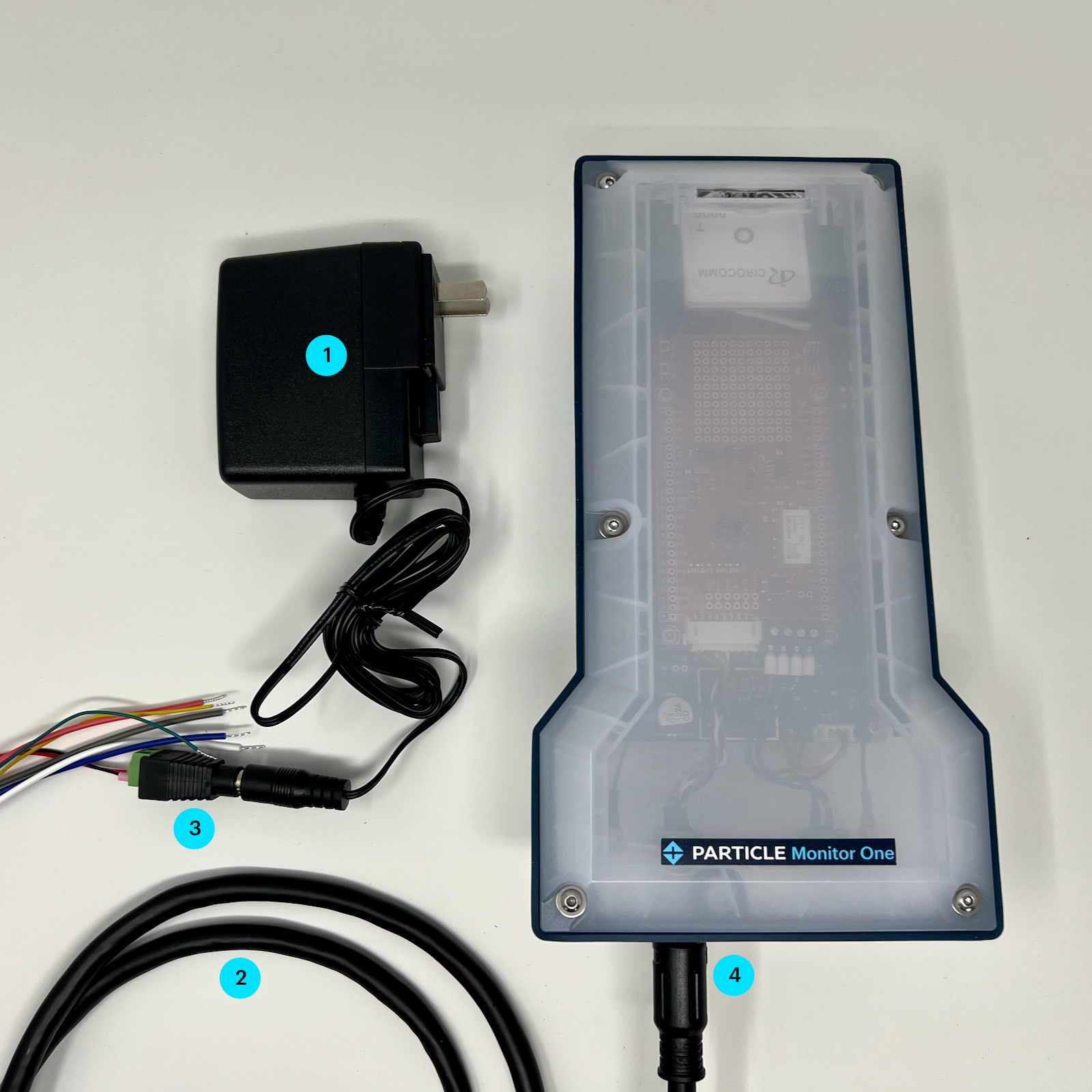
Powering the Monitor One
The Monitor One Developer Edition includes a 24V 1A (24W) power adapter (1). Your power adapter may be slightly different.
Locate the M12 8-pin cable (2). There are two cables, a 4-pin and an 8-pin, and the 8-pin is used for power.
The cable includes a barrel connector adapter (3). Connect the 5.5x2.1mm barrel jack on the power adapter to the barrel connector adapter.
Connect the M12 8-pin connector to the Monitor One (4). The 8-pin connector is on the left with the label facing up, closest to the cellular SMA connector. Some threads may be exposed even when the connector is fully seated; this is normal and does not affect the IP67 waterproof rating.
| Label | Feature |
|---|---|
| 1 | Power supply |
| 2 | M12 8-pin to flying leads cable |
| 3 | Barrel connector adapter |
| 4 | M12 8-pin connection to Monitor One |
If you disconnect and reconnect the barrel connector adapter, make sure the + screw terminal is connected to red and the - screw terminal is connected to black. The power supply barrel connector is center positive.
Any 6VDC to 30VDC power adapter at 2A with a 5.5x2.1mm barrel connector, center positive can be used instead, if desired. For automotive use, you can use this power input directly to a 12V or 24V vehicle power system as the power supply is designed to handle transient voltage present on vehicle power systems.
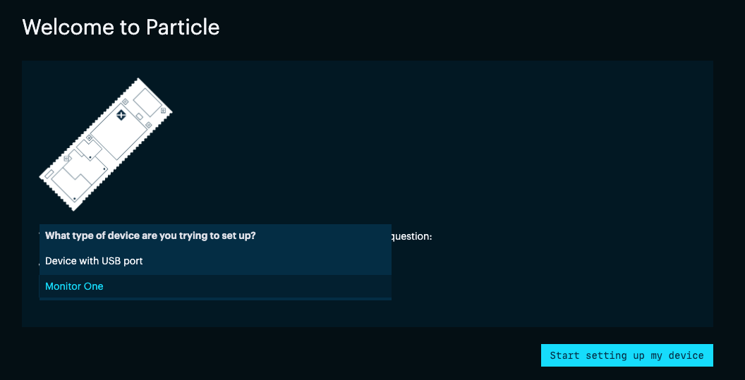
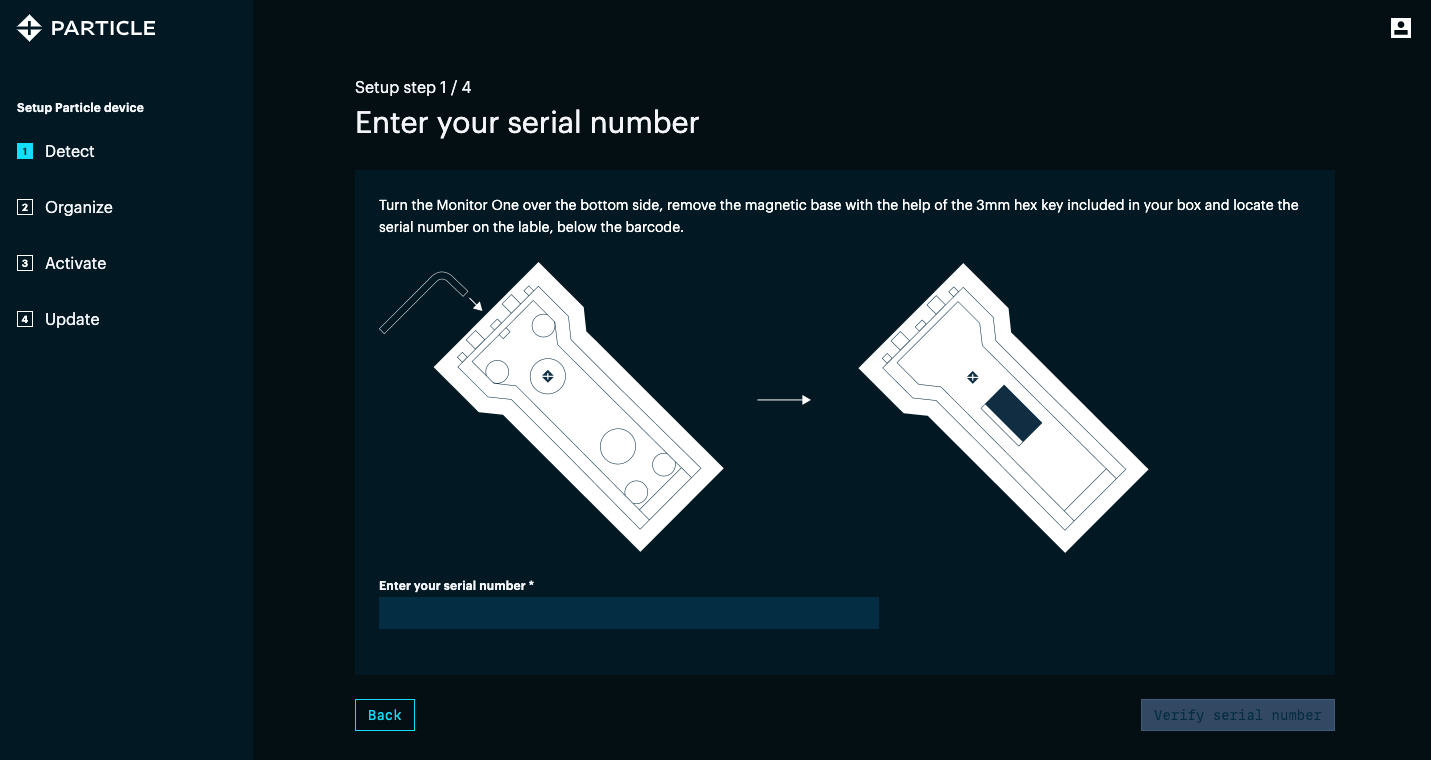
Setting up the device
To set up the device and associate it with your Particle account, visit setup.particle.io. The Monitor One is setup as as Tracker device, as both contain the Tracker SoM module.
At setup.particle.io, you will be given a choice between setting up a device by USB or setting up a Monitor One.
You will then be asked for the serial number. It is available under the mounting plate as pictured.
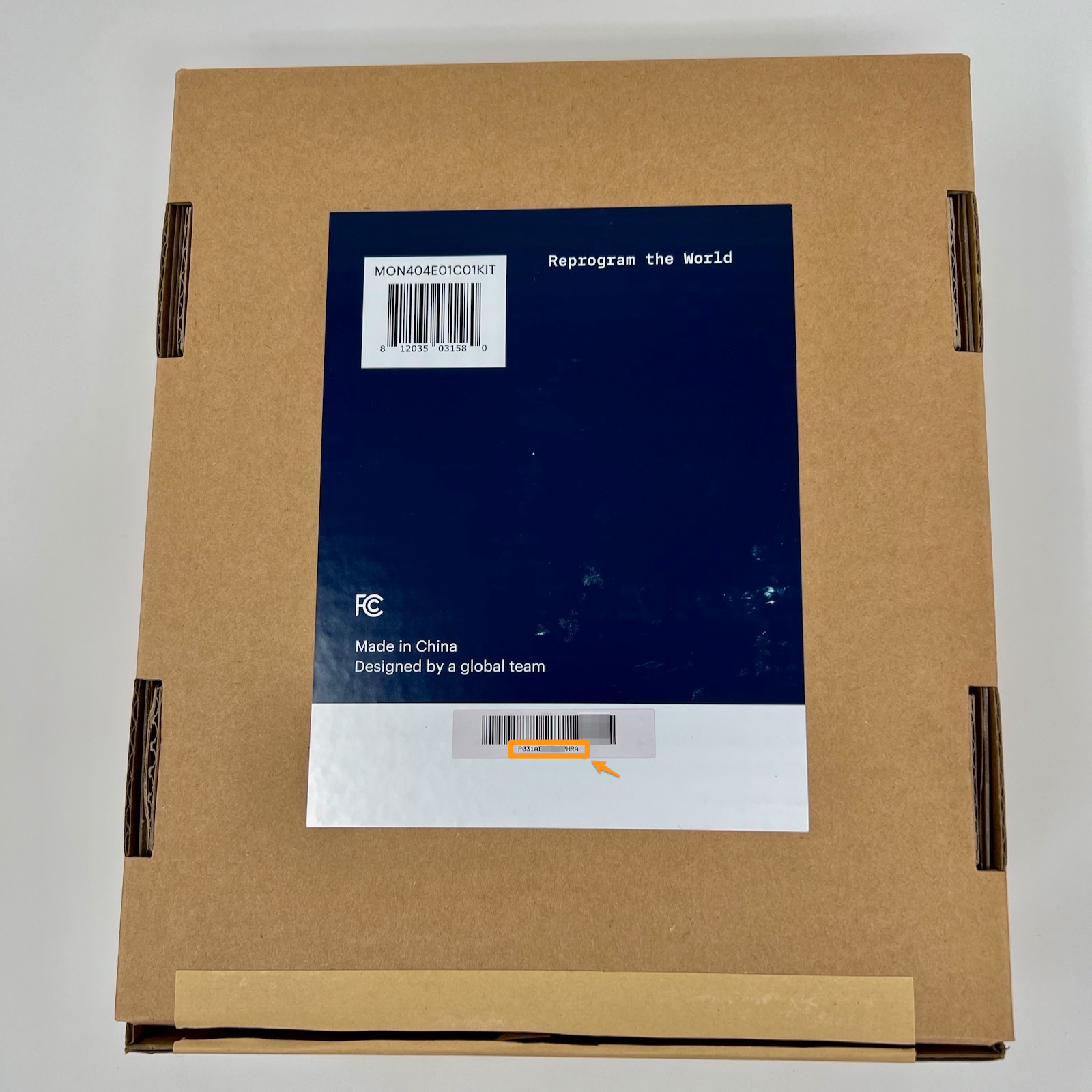
It is also available on the bottom of the box. The serial number begins with "P" and a 3-digit number. It's currently P031 or P032 but this could change.
Just follow the instructions in the setup application to complete setup.
Next steps
Console
The Particle console is where you can view and configure your Monitor One, or an entire fleet of devices.
The console getting started guide is a good place to start.
In some cases, you can configure your Monitor One settings entirely from the cloud may not need custom firmware at all.
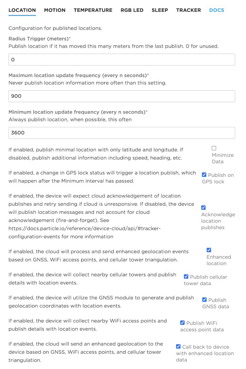
Monitor Edge allows cloud-based configuration of many parameters, and you can add custom tabs and items that display in the Particle console in your Monitor One product. See Tracker Configuration for more information.
Particle Workbench
Particle Workbench is the development environment for the Monitor One. From that link you can download Workbench, based on Visual Studio Code, for Windows, Linux, and Mac.
Monitor Edge
The firmware on the Monitor One is Monitor Edge, which is included on the device but is open source and can be customized for your specific application. From this page you can also view the release notes for Monitor Edge releases.
It builds on the standard features of Particle device firmware and the Device OS API:
For further technical information about the Monitor One, see the Monitor One datasheet.