
Monitor One datasheet
The Monitor One is an off-the-shelf complete gateway design, like the Tracker One. The Monitor One is in a larger IP67 waterproof enclosure with room inside for an expansion card and additional connectors, allowing it to be used in more custom scenarios than the Tracker One.
- Ready to go with rugged IP67-rated enclosure with room inside for an expansion card.
- Flexible power supply to easily add asset tracking to most devices with a 6 - 30 VDC power input and a large 18650 LiPo battery pack.
- Internal or external antennas for cellular and GNSS.
- Temperature sensors on the carrier board, and also a battery pack temperature sensor.
- Expansion card connector to allow for custom application specific hardware.
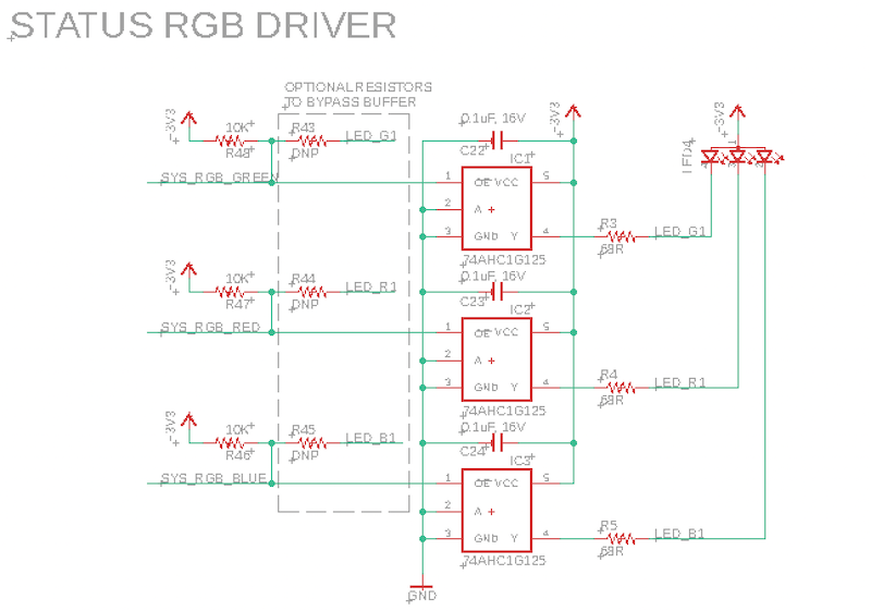
- RGB LED for system status, and two user RGB LEDs for your own use, visible from outside the enclosure.
- User button, waterproof and accessible from outside the enclosure.
Particle gateway device like the Monitor One and Tracker One are designed to be used off-the-shelf to interface to other devices and sensors using standard protocols such as CAN bus, I2C, and serial.
For information on setting up a Monitor One Developer Edition, see the Monitor One Quickstart.
The pictures in this datasheet are of a pre-release unit.
Block diagram
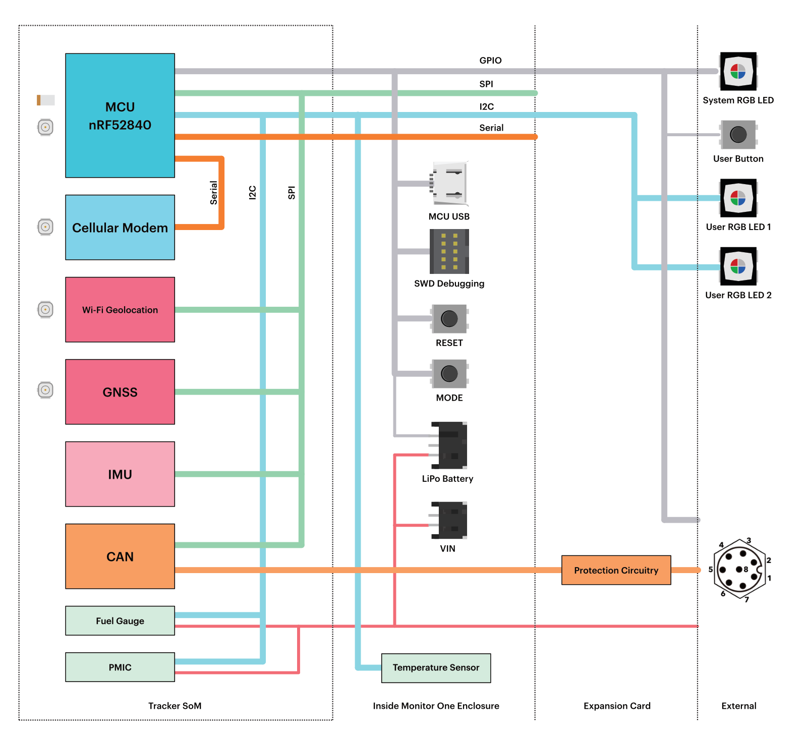
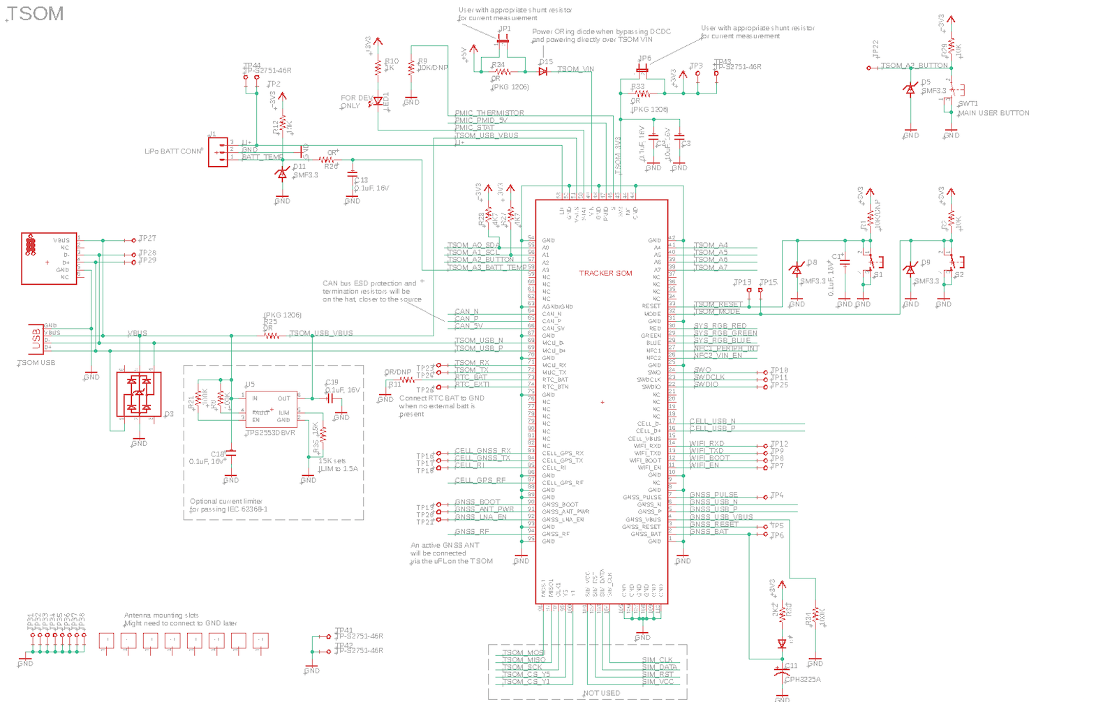
Details about the Tracker SoM that is contained within the Monitor One can be found in the Tracker SoM Datasheet.
External features
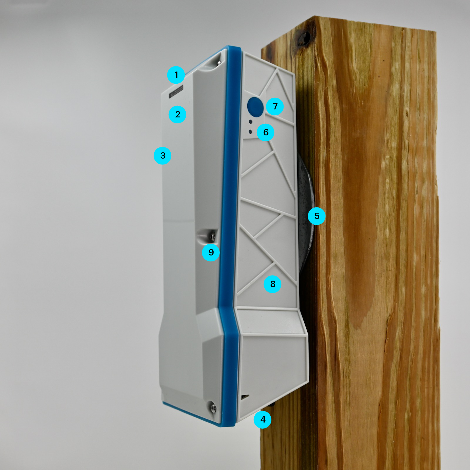
| Label | Feature |
|---|---|
| 1 | System RGB LED |
| 2 | GNSS antenna (internal) |
| 3 | Cellular antenna (internal) |
| 4 | External connectors (on bottom) |
| 5 | Magnetic, bolt-down, or strap-down mounting bracket |
| 6 | User RGB LEDs (2) |
| 7 | User button (externally accessible) |
| 8 | Wi-Fi geolocation antenna (internal, optional) |
| 9 | Cover screws (6) (M2 hex, 2mm) |
User button
A waterproof button is available from the outside of the enclosure.
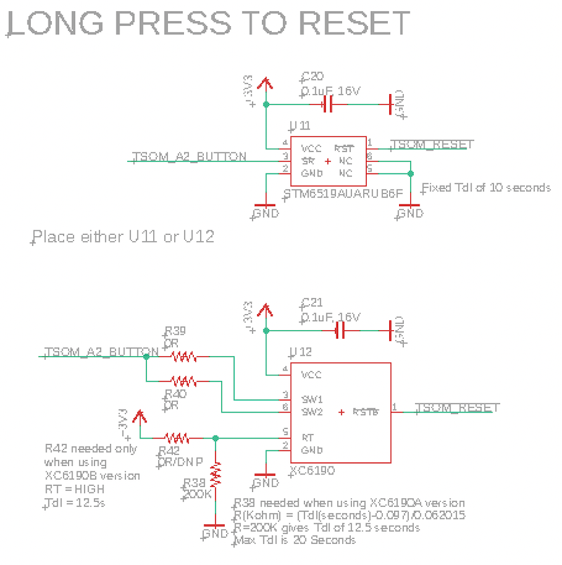
- Long press (10 seconds) resets the device (as if the RESET button was pressed)
- Shorter press and multiple press can be handled by your user firmware for your own features
User LEDs (2)
- There are two small RGB LEDs visible from the outside on the side of the unit, next to the user button.
- The upper LED defaults to being a GNSS lock indicator:
- Off: GNSS off
- Blinking (green): attempting to get a GNSS fix
- On (green): GNSS fix acquired
- You can program custom colors, blinking, and fade effects from your user firmware for the lower LED.
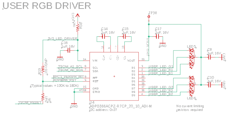
- LEDs are controlled by a ADP8866 I2C LED controller.
Connectors
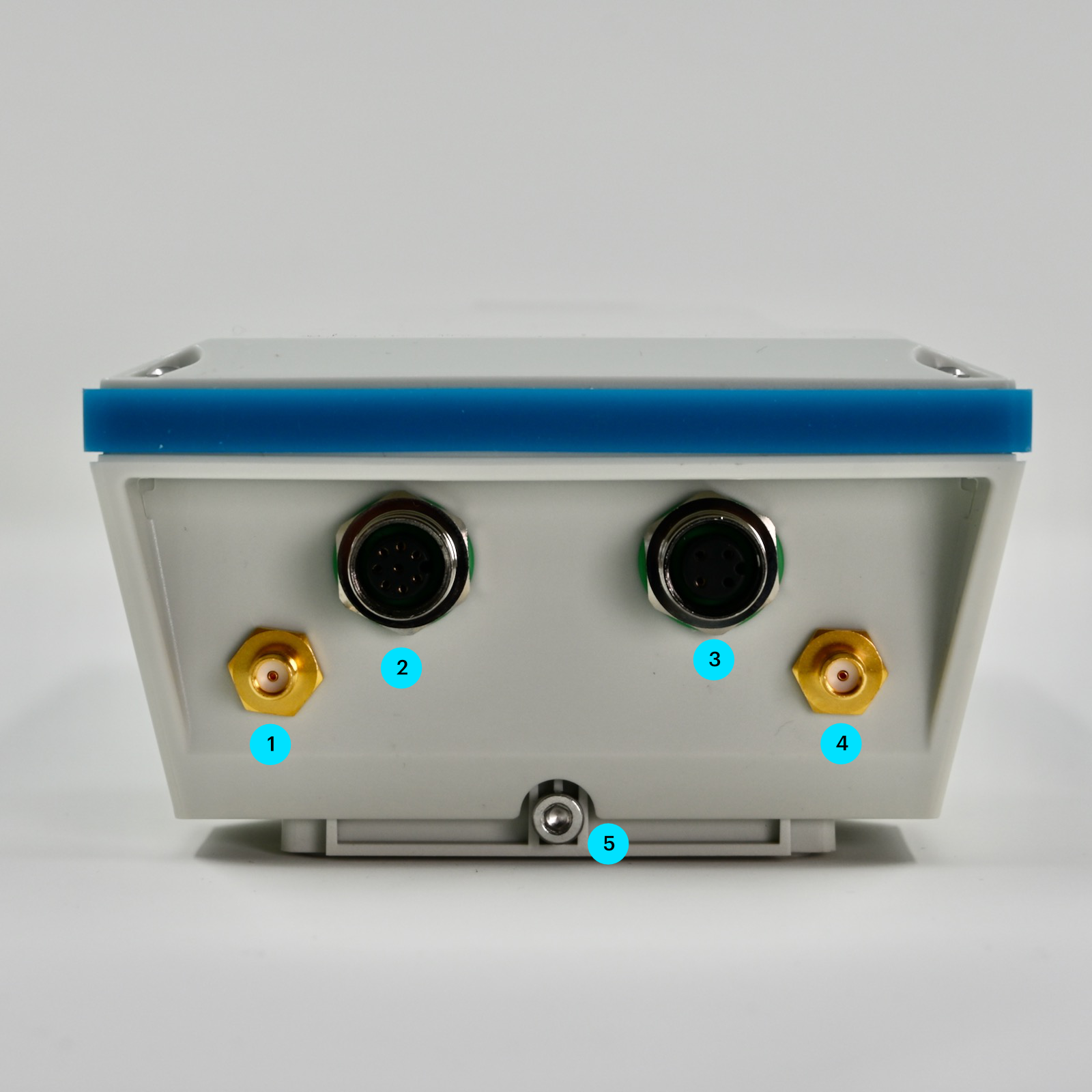
The bottom plate of the Monitor One can be customized with different connectors for your application.
| Label | Feature |
|---|---|
| 1 | Cellular antenna (SMA) |
| 2 | M12 connector (8-pin) |
| 3 | M12 connector (4-pin) |
| 4 | GNSS antenna (SMA) |
| 5 | Mounting plate attachment screw |
By default the Monitor One uses the internal cellular and GNSS antennas, but can be switched to using the external connectors inside the enclosure.
The cellular (1) and GNSS (4) antennas are not connected internally at the factory. In order to use the external connectors you must open the case, disconnect the internal antenna, and instead connect the U.FL connector for the external jack.
The Monitor One is equipped with 2 external-facing SMA bulkhead connectors for both cellular and GNSS but are disconnected internally. The hardware is ready for use with external antennas giving the ability to connect a wide variety of application-specific antennas. It is recommended that the user perform required RF certifications with the selected antenna installed as the Monitor One has only been certified for use in select regions with the internal antennas. The specifications for this cable are in the SMA to JST cable datasheet (pdf).
Mounting
The Monitor One is intended to be mounted in the orientation shown at the top of the page, with the connectors facing down. You can also mount it with the mounting plate mounted on a flat surface as the GNSS antenna is angled to allow it to work in either orientation.
When using external cellular and GNSS antennas you can orient the Monitor One in other directions.
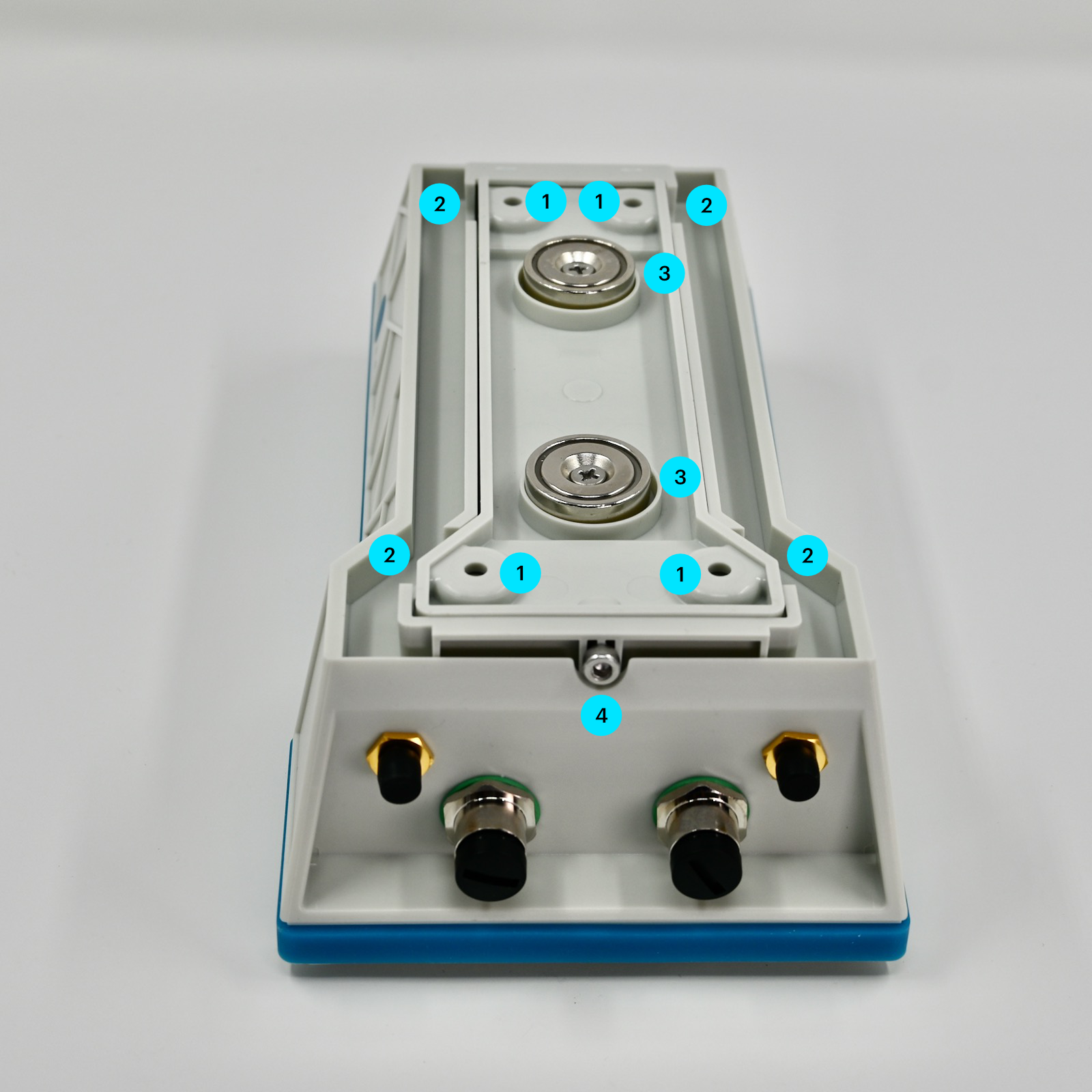
| Label | Details |
|---|---|
| 1 | Mounting screw or bolt holes |
| 2 | Slots for strap mounting |
| 3 | Magnets |
| 4 | Mounting plate removal screw (M3 hex, 3mm) |
The mounting plate contains two magnets (3) that allow it to be easily mounted on a metal surface.
The mounting plate is removable from the back of the unit after removing the screw on the bottom (4), near the expansion connectors.
Once removed, you can screw or bolt the mounting plate through the four holes (1) and reattach the Monitor One. This is good for rough conditions and for mounting on non-metal surfaces.
The mounting plate can be strap mounted through the two slots (2).
The magnets do not need to removed to use screw, bolt, or strap mounting.
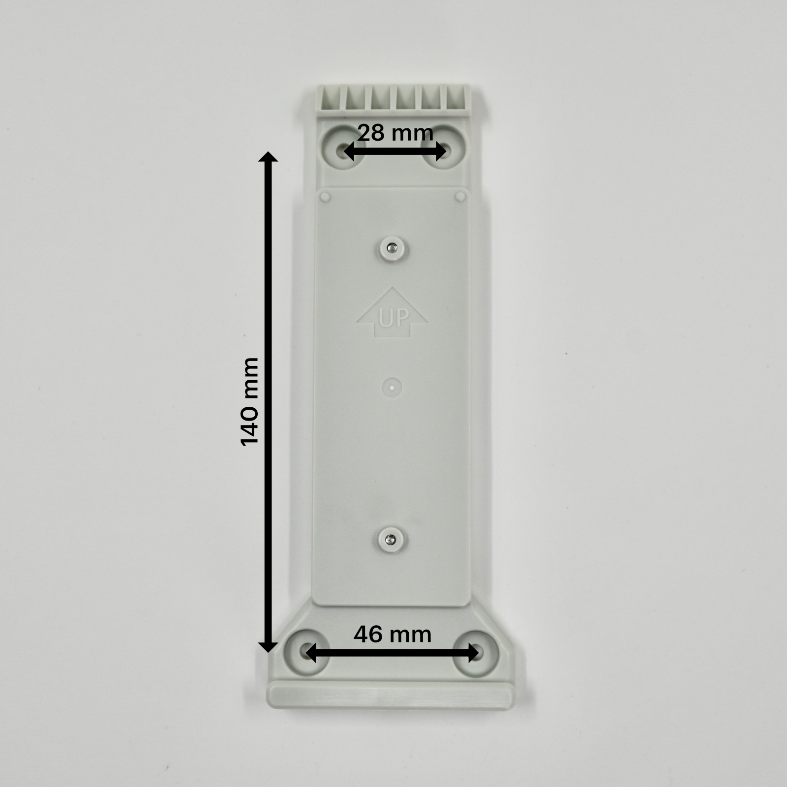
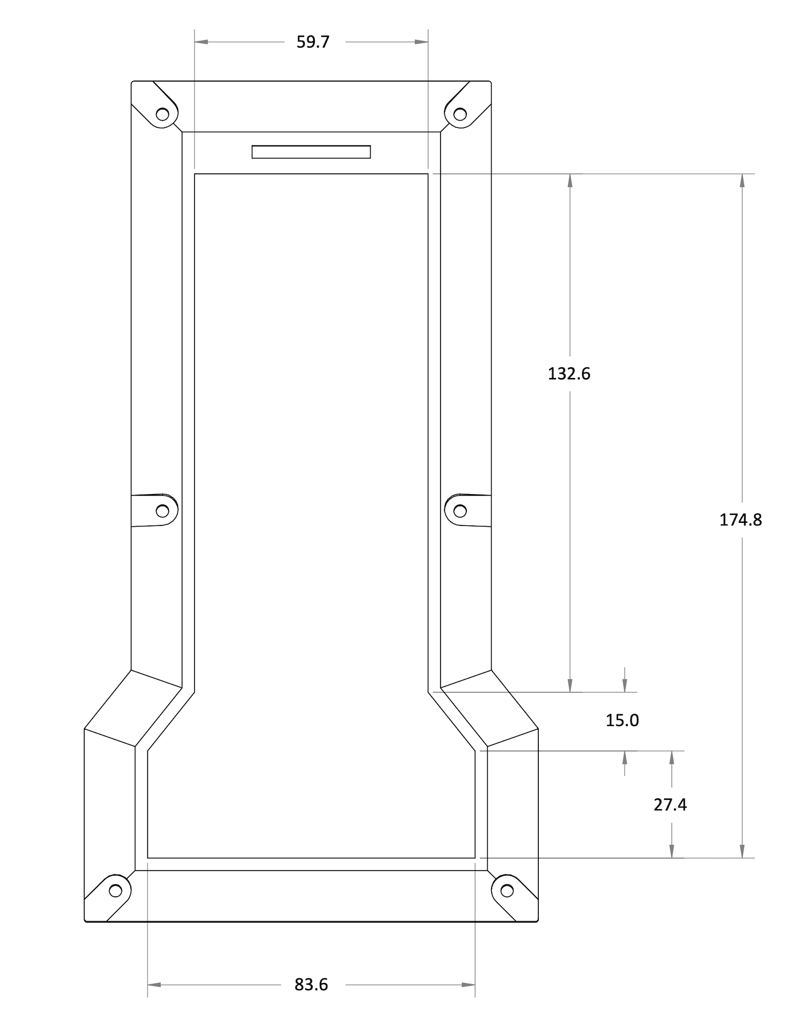
| Dimensions | Metric | SAE |
|---|---|---|
| Top, width between mounting holes | 28 mm | 1 3/32" |
| Bottom, width between mounting holes | 46 mm | 1 13/16" |
| Height between mounting holes | 140 mm | 5 1/2" |
| Dimensions | Metric | SAE |
|---|---|---|
| Bolt/screw head hole diameter (maximum) | 12.46 mm | 31/64" |
| Bolt/screw head maximum height (maximum) | 4.0 mm | 5/32" |
| Bolt/screw hole diameter (maximum) | 4.33 mm | 11/64" |
| Bolt/screw shaft to surface (maximum) | 3.65 mm | 9/64" |
| Recommended bolt or screw | M4 | #8 |

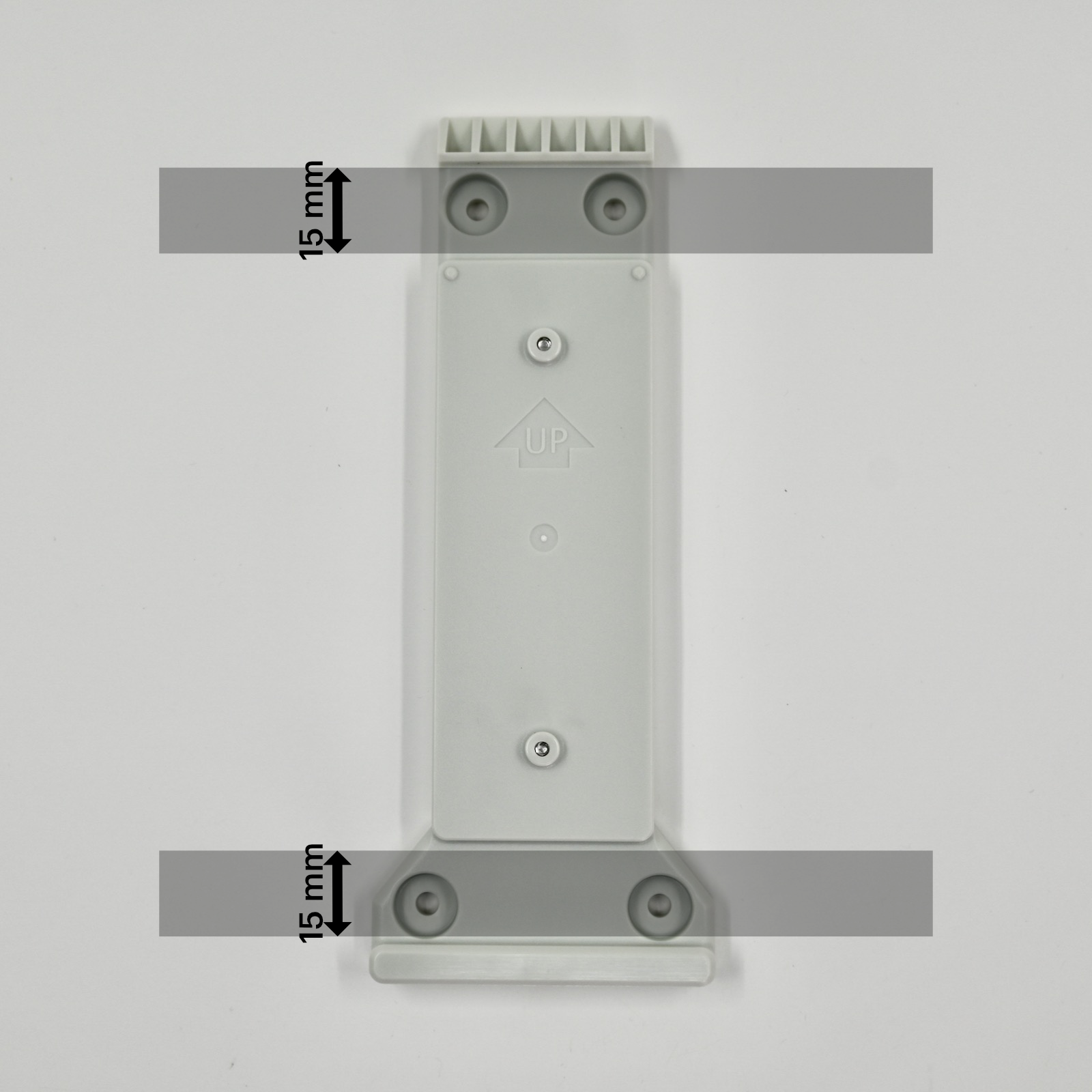
When mounting using a strap, the strap will hold the mounting bracket against a surface and is sandwiched between the mounting bracket and the Monitor One enclosure.
| Dimensions | Metric | SAE |
|---|---|---|
| Maximum strap width | 15 mm | 19/32" |
If you wish to fabricate your own compatible mounting bracket, the STEP file can found in the Monitor One Github repository.
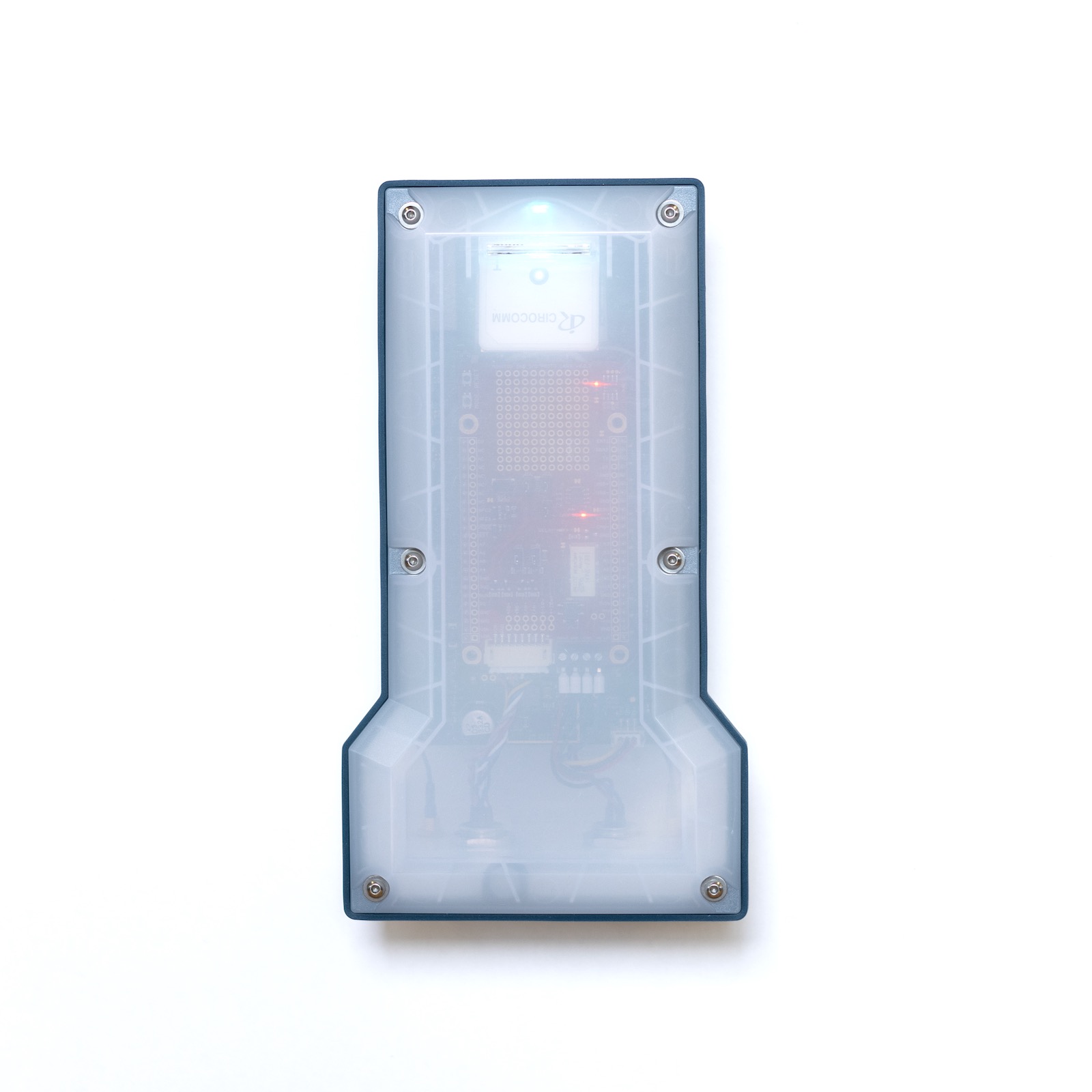
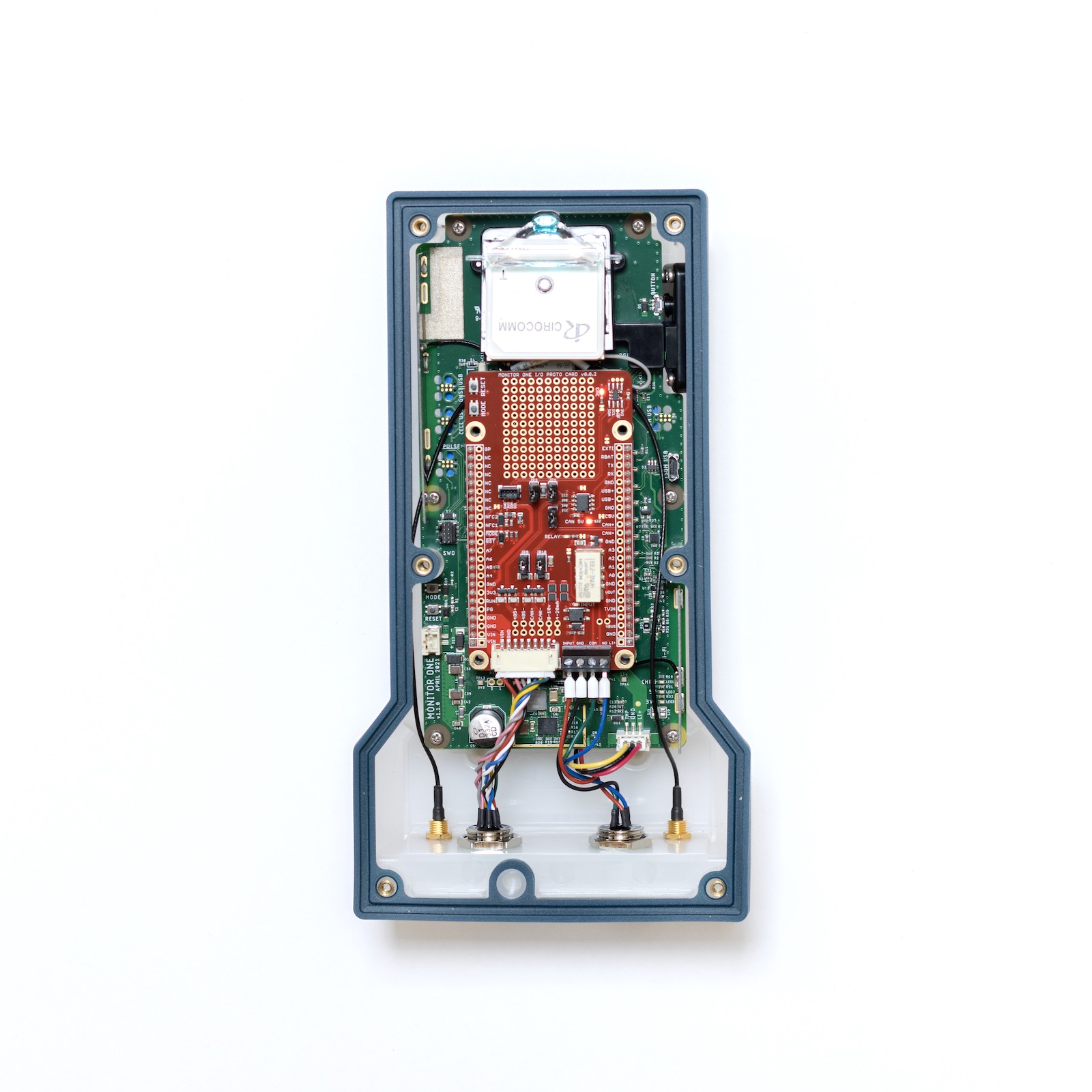
Internal features
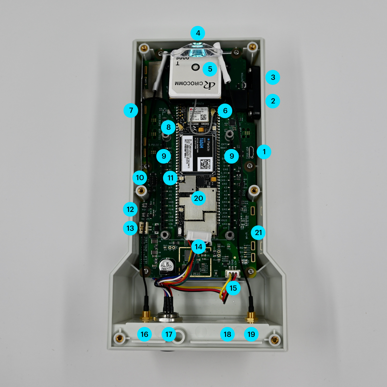
| Label | Feature |
|---|---|
| 1 | MCU USB Connector (Micro B) |
| 2 | User RGB LEDs (2, externally visible) |
| 3 | User Button (externally accessible) |
| 4 | System RGB LED (externally visible) |
| 5 | GNSS antenna (internal, optional) |
| 6 | GNSS antenna U.FL connector |
| 7 | Cellular antenna (internal) |
| 8 | Cellular antenna U.FL connector |
| 9 | Expansion card headers (2) |
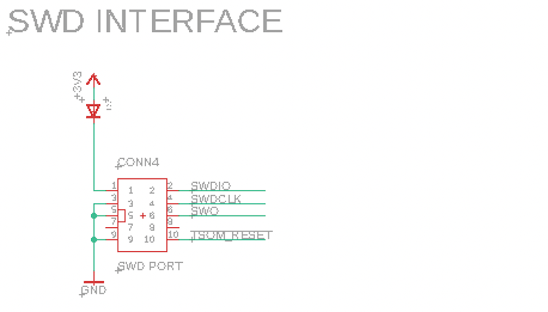
| 10 | SWD debugging connector |
| 11 | Wi-Fi geolocation antenna U.FL connector |
| 12 | MODE and SETUP buttons |
| 13 | VIN connector |
| 14 | Expansion card to external connector cable |
| 15 | LiPo battery connector |
| 16 | Cellular antenna SMA connector (external) |
| 17 | Expansion card external connector #1 (M12, 8-pin) |
| 18 | Expansion card external connector #2 (M12) |
| 19 | GNSS antenna SMA connector (external) |
| 20 | Tracker SoM module |
| 21 | Wi-Fi geolocation antenna (internal, not pictured) |
I/O Card
The Monitor One is designed with easy-to-use expansion headers and an enclosure with sufficient space inside for an expansion card, and for additional expansion connector through the wall of enclosure.
The Monitor One Developer's Edition includes the I/O Card, which includes:
| Feature | Location | Details |
|---|---|---|
| VIN | M12 8-pin | Power input, 6 - 30V DC |
| CAN Bus | M12 8-pin | |
| RS485 (Modbus) | M12 8-pin | |
| 4-20 mA input | M12 8-pin | |
| 0-10V analog input | M12 8-pin | |
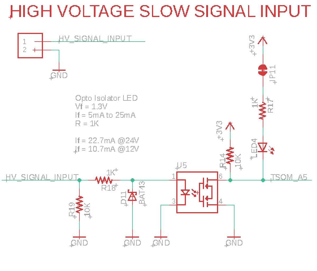
| 12-24V slow-signal input | M12 4-pin | Opto-isolated |
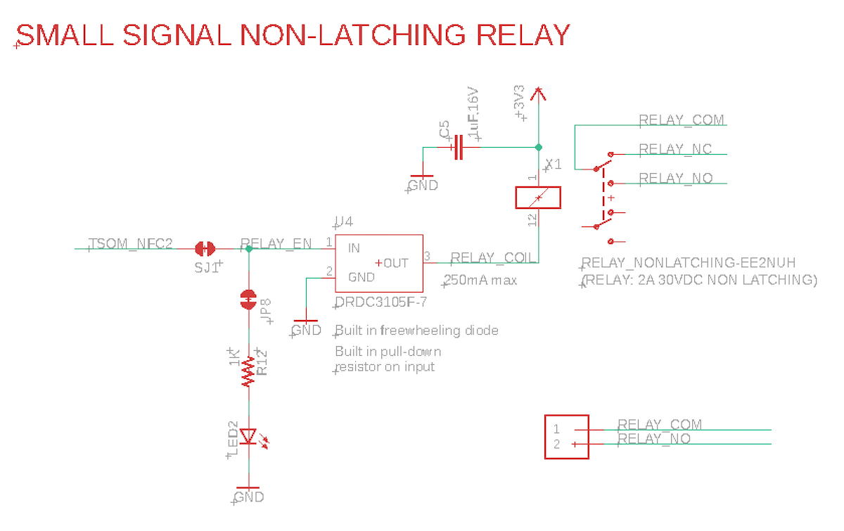
| Relay | M12 4-pin | 30VDC 2A maximum |
| QWIIC connector | expansion card | 3.3V I2C |
I/O Card M12 8-pin to flying leads
The Monitor One includes a M12 8-pin male to flying leads cable, 1500±20mm (about 60 inches or 5 feet). This is used to power the Monitor One, and also use the 4-20mA, 0-10V analog in, CAN bus, and RS485 (Modbus) interfaces.
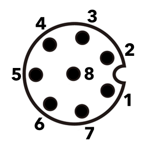
Looking at the pins on the end of the connector on the cable
| Conn P1 (M12) | Color | Function | GPIO |
|---|---|---|---|
| 1 | White | CAN_P | |
| 2 | Red | VIN (6-30 VDC) | |
| 3 | Green | 4-20mA input | A7 |
| 4 | Yellow | 0-10V input | A6 |
| 5 | Gray | RS485_B (N) | |
| 6 | Pink | RS485_A (P) | |
| 7 | Blue | CAN_N | |
| 8 | Black | Ground |
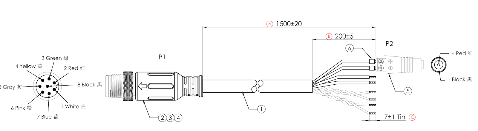
Also included is an adapter from screw terminals to a 5.5x2.1mm barrel jack, center positive. If you disconnect and reconnect the adapter, make sure the + screw terminal is connected to red and the - screw terminal is connected to black. An appropriate 24 VDC power adapter is included.
Any 6VDC to 30VDC power adapter at 12 watts (minimum) with a 5.5x2.1mm barrel connector, center positive can be used instead, if desired. For automotive use, you can use this power input directly to a 12V or 24V vehicle power system as the power supply is designed to handle transient voltage present on vehicle power systems.
The RS485 and CAN interface pins on the M12 8-pin connector cannot be used as GPIO.
See M12 connector ratings below for voltage and current limits for this connector.
I/O Card M12 4-pin to flying leads
The Monitor One includes a M12 4-pin male to flying leads cable, 1500±20mm (about 60 inches or 5 feet).
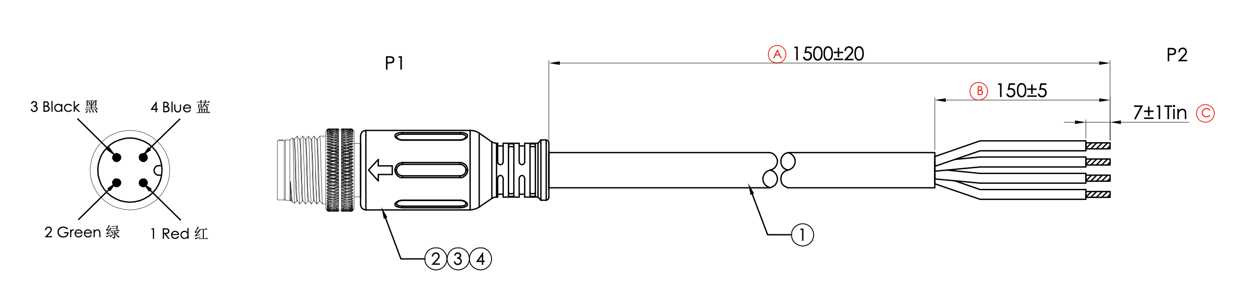
| Conn P1 (M12) | Color | Function | GPIO |
|---|---|---|---|
| 1 | Red | 12-24V slow-signal input | A5 |
| 2 | Green | Relay COM | |
| 3 | Black | Ground | |
| 4 | Blue | Relay (NO) | NFC_PIN2 |
See M12 connector ratings below for voltage and current limits for this connector.
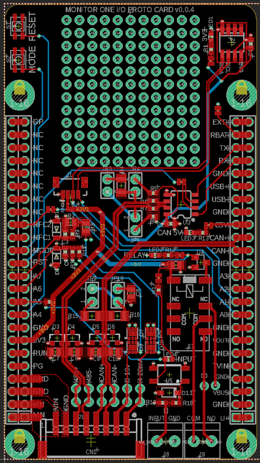
I/O Card details
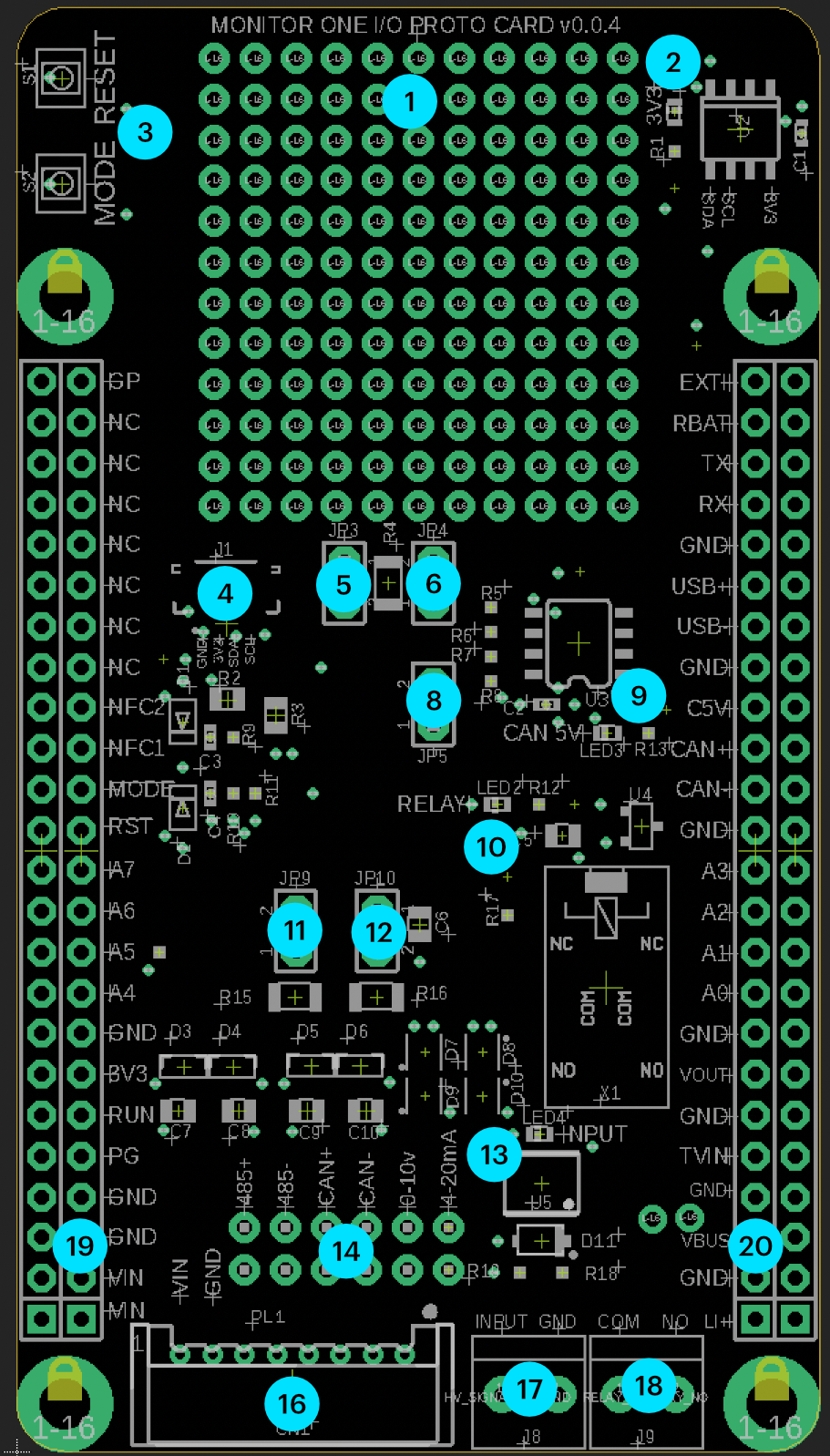
| Label | Details |
|---|---|
| 1 | Prototyping area |
| 2 | Power LED (LED1) |
| 3 | RESET and MODE buttons |
| 4 | QWIIC (I2C) connector |
| 5 | RS-485 120 ohm termination resistor enable (JP3) |
| 6 | RS-485 pull-up resistor (JP4) |
| 8 | RS-485 pill-down resistor (JP5) |
| 9 | CAN_5V LED (LED3) |
| 10 | Relay energized LED (LED2) |
| 11 | CAN termination resistor enable (JP9) |
| 12 | CAN termination capacitor enable (JP10) |
| 13 | Slow-signal input (12-24V) powered (LED4) |
| 14 | M12 8-pin solder jumpers, location for prototyping wires |
| 16 | Connector to M12 8-pin |
| 17 | Slow-signal input (12-24V) and GND |
| 18 | Relay COM and NO (normally open) |
| 19 | Access to expansion card signals |
| 20 | Access to expansion card signals |
The M12 4-pin bulkhead connector has flying leads that are connected to the screw terminals (18) as follows:
| M12 Pin | Color | Card |
|---|---|---|
| 1 | Red | INPUT |
| 2 | Green | COM |
| 3 | Black | GND |
| 4 | Blue | NO |
Customizing the I/O Card
If you wish to build upon the I/O Card, there is a small prototyping area (1).
If you need signals from the expansion card interface, they are available in the rows of pins (19, 20).
If you wish to disable an interface that you are not using and re-use the pins on the M12 8-pin connector, there is a small trace jumper between the rows of pins in area (14). Cutting this trace isolates the expansion card signal from the signal to the connector (16). Then you can solder a small jumper wire to replace the signal on the M12 8-pin.
The Eagle CAD schematic and board layout files for the I/O card can be found in the Monitor One Github repository.
Block diagram - I/O Card
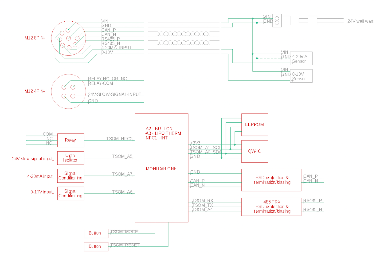
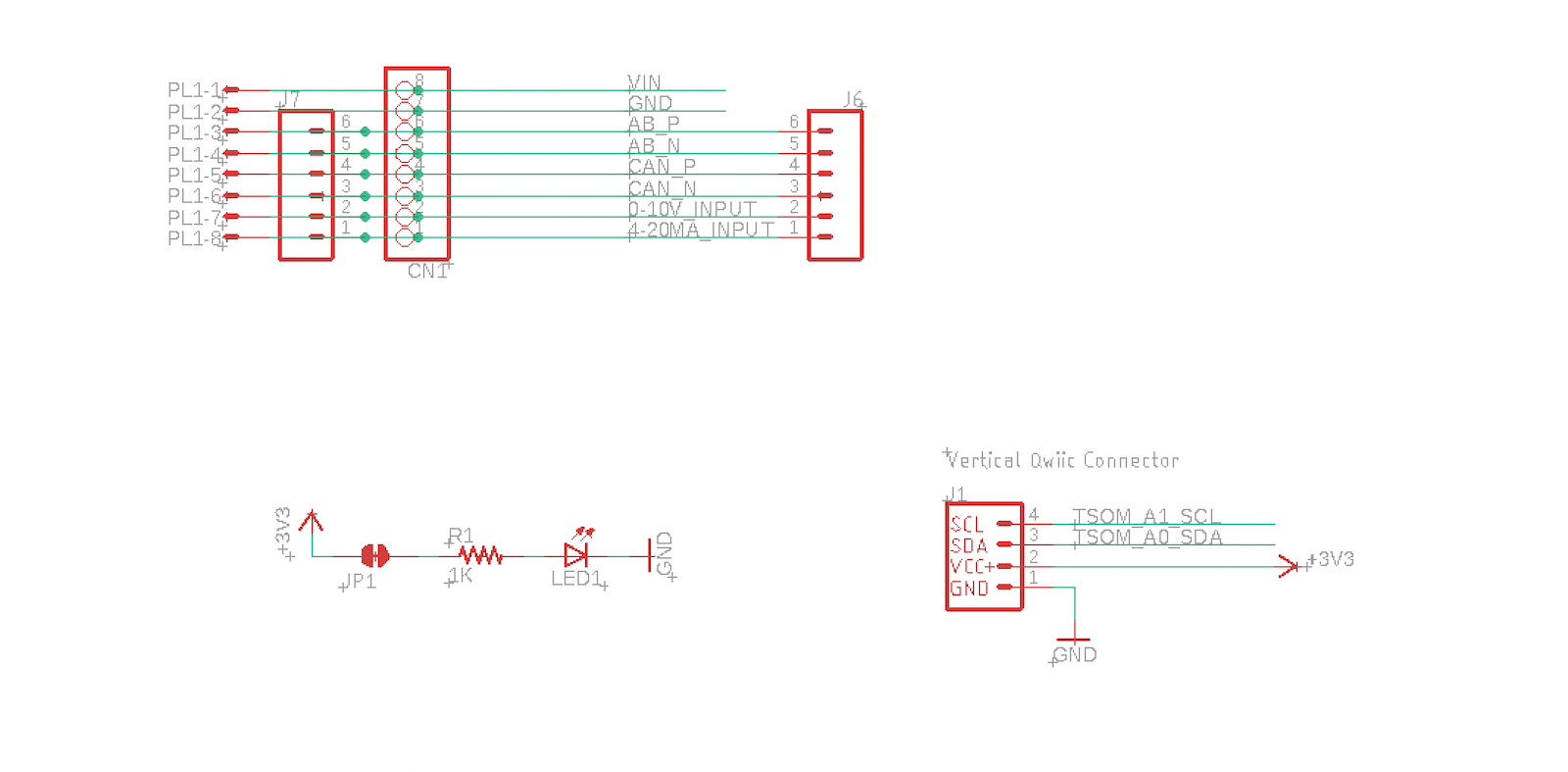
Schematics - I/O Card
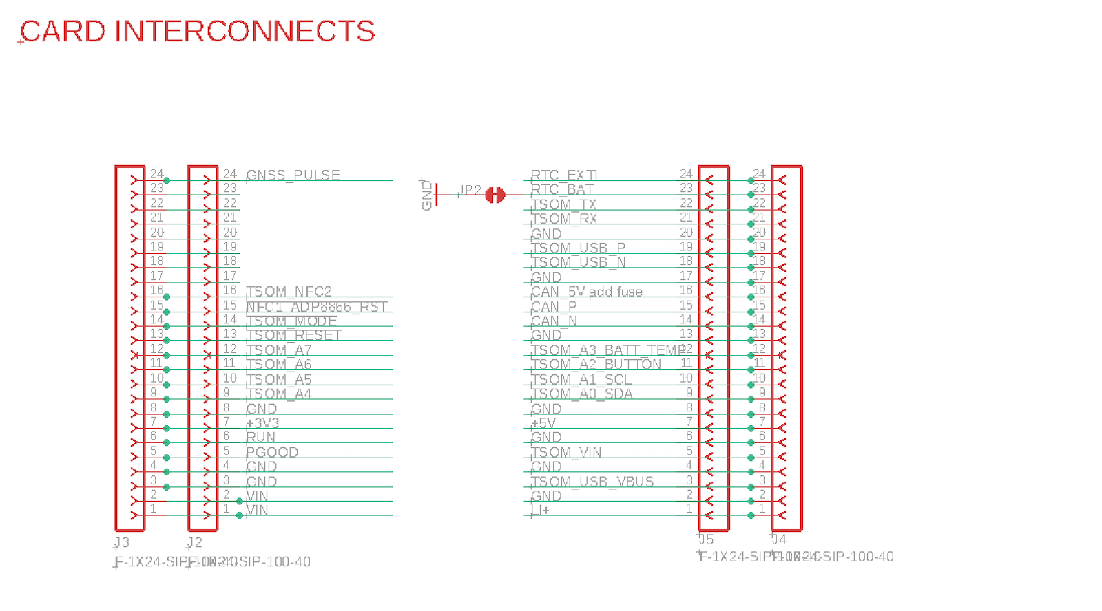
Interconnects - I/O Card
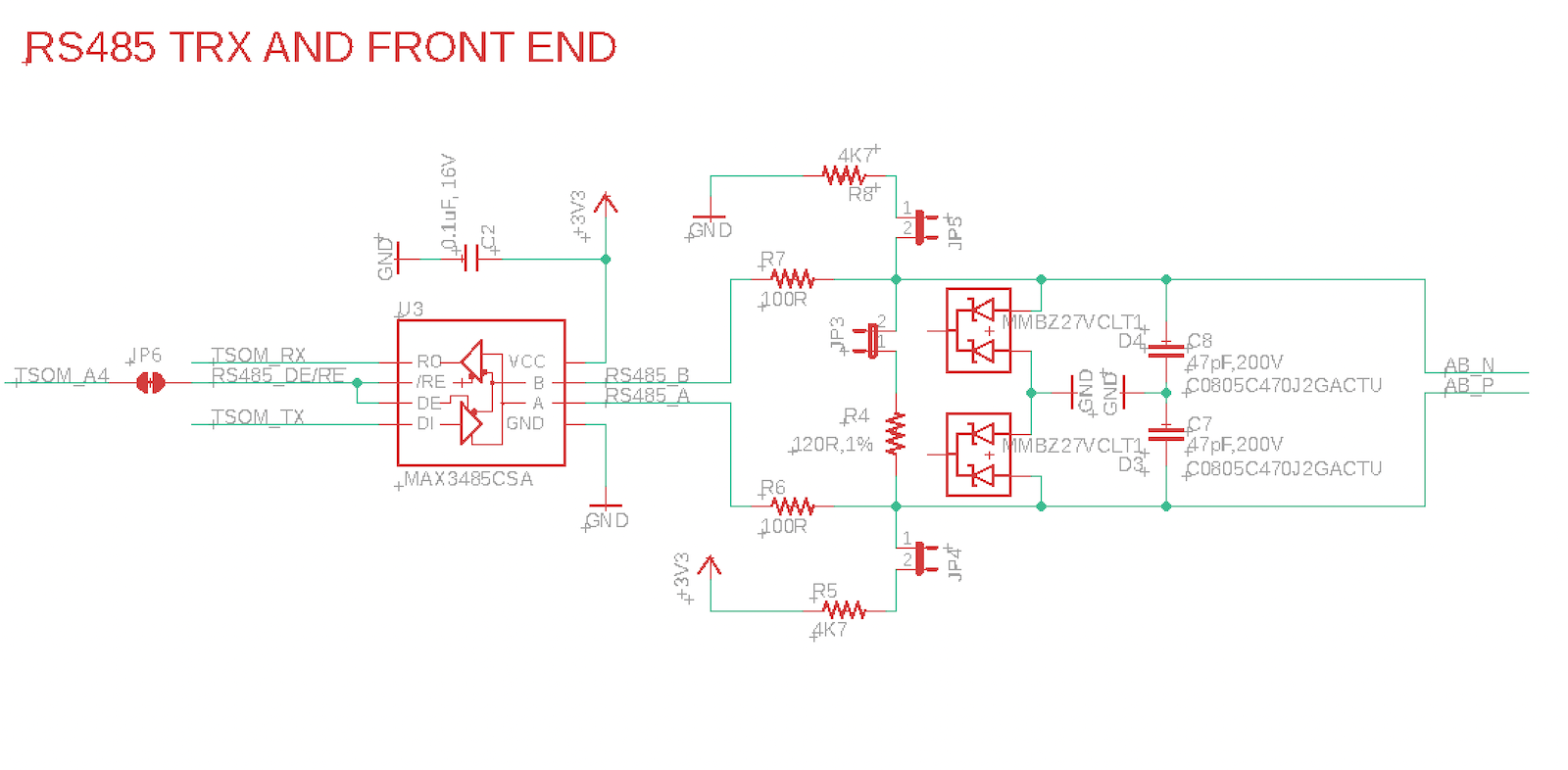
RS485 - I/O Card
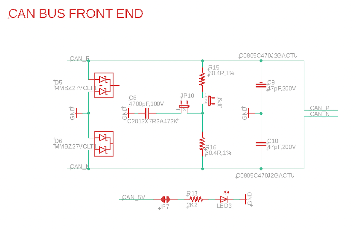
CAN - I/O Card
4-20mA - I/O Card
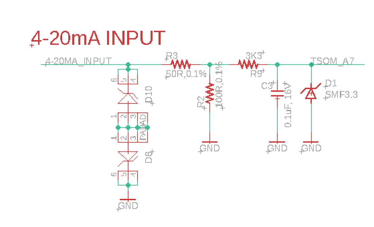
The A7 pin measures the voltage across R2, which is 100Ω.
| Current | V=IR | Voltage | ADC Value |
|---|---|---|---|
| 0 mA | 0.000A × 100Ω = | 0.0V | 0 |
| 4 mA | 0.004A × 100Ω = | 0.4V | 496 |
| 20 mA | 0.020A × 100Ω = | 2.0V | 2482 |
| 33 mA | 0.033A × 100Ω = | 3.3V | 4095 |
R9 just limits the current that needs to be sunk via D1 if the current exceeds 33 mA and does not affect the ADC voltage.
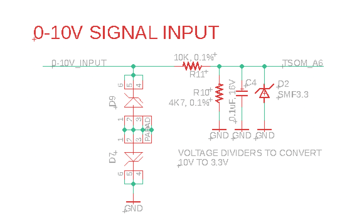
0-10V - I/O Card
Slow signal input - I/O Card
Relay - I/O Card
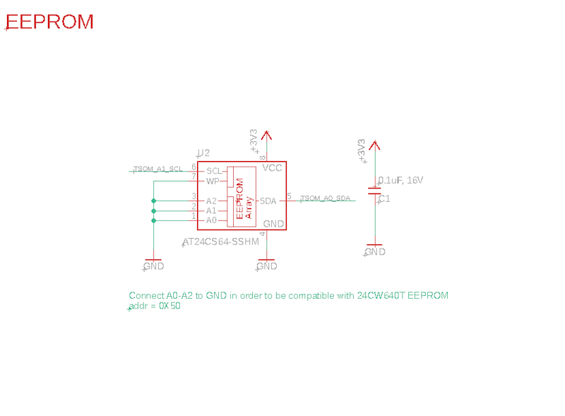
EEPROM - I/O Card
Board layout - I/O Card
Prototype Card
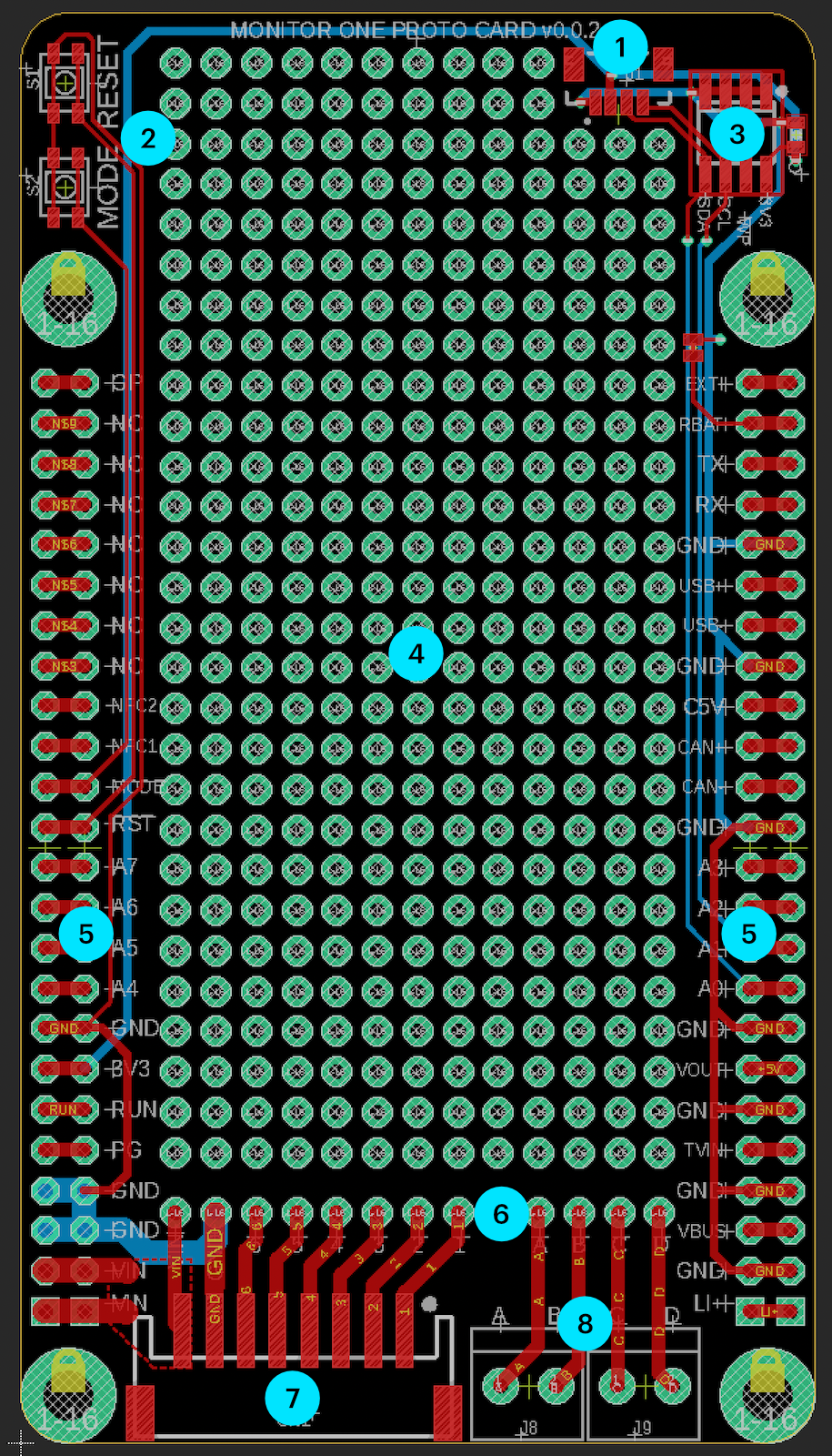
| Label | Feature |
|---|---|
| 1 | QWIIC (I2C) connector |
| 2 | RESET and MODE buttons |
| 3 | EEPROM |
| 4 | Prototyping area |
| 5 | Access to expansion port signals |
| 6 | Access to bulkhead connector signals |
| 7 | B8B-PH connector, connect to M12 8-pin |
| 8 | Screw terminals, connect to M12 4-pin |
B8B-PH connector
The left connector (7) attaches to the M12 8-pin connector with a short adapter cable. You don't have to use this cable setup, but it's often convenient to do so.
- Connector: JST B8B-PH (right angle)
- Mates with: JST PHR-8
| Connector B8B-PH | Color | M12 Pin | Function |
|---|---|---|---|
| 8 | 2 | Red | VIN (6-30 VDC) |
| 7 | 8 | Black | Ground |
| 6 | 6 | Pink | |
| 5 | 5 | Gray | |
| 4 | 1 | White | |
| 3 | 7 | Blue | |
| 2 | 4 | Yellow | |
| 1 | 3 | Green |
- We recommend that you keep pin 8 (VIN) and pin 7 (GND) is the same positions.
- Other pins can be used as desired.
- The pins on the board layout are numbered 8 - 1 left to right, opposite of how the pins on the cable are numbered.
Screw terminals
| Screw Terminal | Color | M12 Pin |
|---|---|---|
| A | Red | 1 |
| B | Black | 3 |
| C | Green | 2 |
| D | Blue | 4 |
- The order of these pins isn't significant, but this is how the I/O Card is wired, so it probably best to be consistent.
Schematics - Prototyping Card
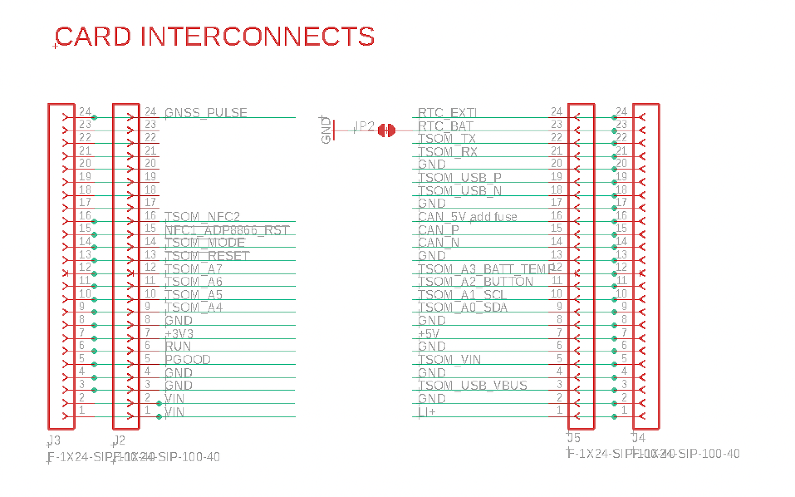
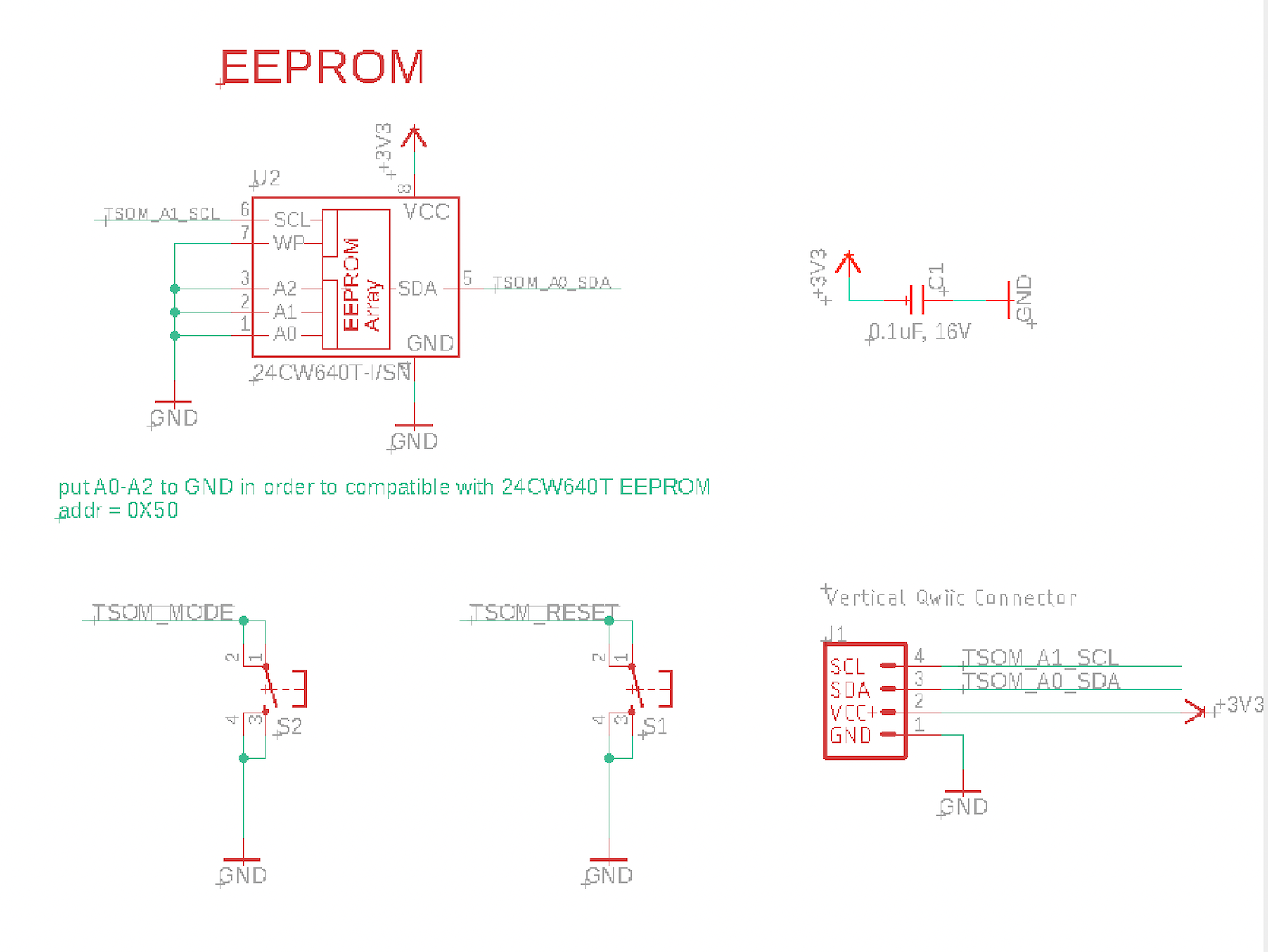
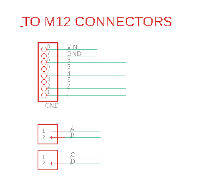
The Eagle CAD schematic and board layout files for the prototype can be found in the Monitor One Github repository.
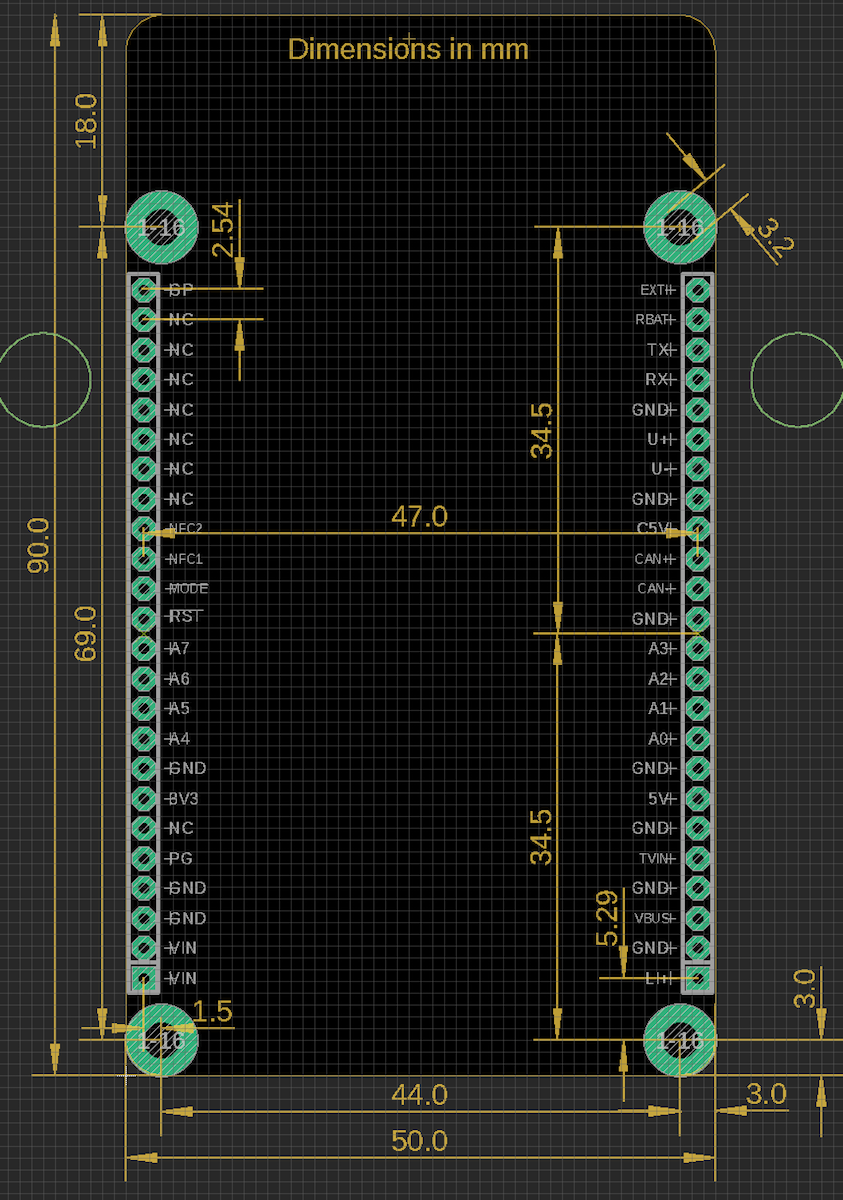
Expansion card interface
- Expansion card size: 50mm x 90mm (approximately 2" x 3.5")
- Connectors: 24-pin 0.1" headers (two, one on each long side)
- Male header pins on the bottom of expansion card
- Attachment: 4 screws to standoffs (M3 screw recommended)
Pre-built expansion cards will be available, including the Prototype Card. You can also design and fabricate your own.
If you are building your own card, you can start with the design for the I/O card or prototype card. The Eagle CAD schematic and board layout files can be found in Monitor One Github repository.
Expansion card pinout

Expansion card dimensions
Expansion card location
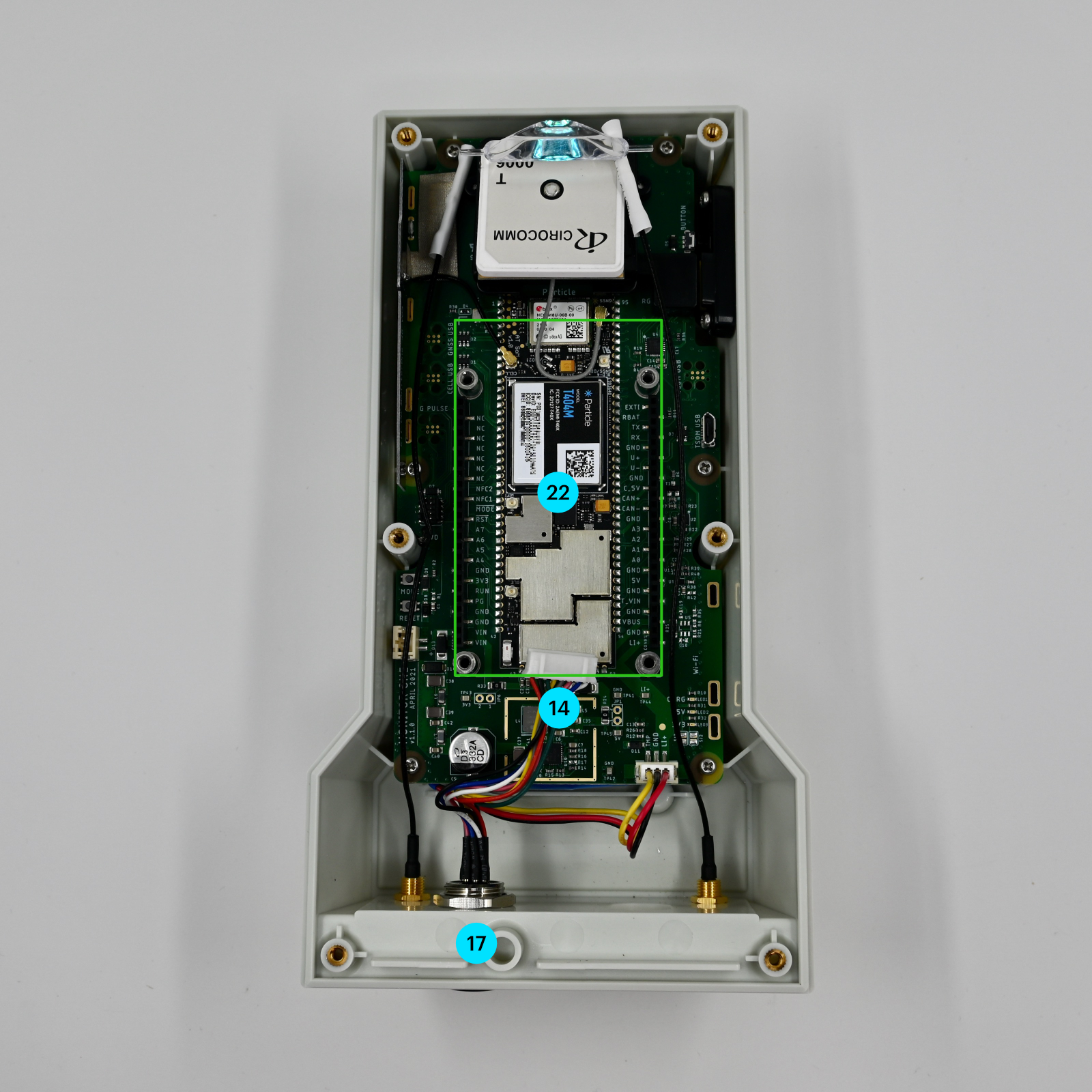
| Label | Feature |
|---|---|
| 14 | Expansion card to external connector cable (M12 to PHR8) |
| 17 | Expansion card external connector #1 (M12, 8-pin) |
| 22 | Location of expansion card (green outline) |
The enclosure typically has a panel-mount M12 8 pin female connector in location 17 in the picture above. This is connected via a short cable to a PHR-8 female connector that attaches to your expansion card. The picture above shows the cable but a board is not installed in the picture.
The functions of the pins on the M12 8-pin connector are dependent on your base board, but the following pinouts are recommended:
| Conn P1 (M12) | Conn P2 (PHR-8) | Color | Function |
|---|---|---|---|
| 2 | 1 | Red | VIN (6-30 VDC) |
| 8 | 2 | Black | Ground |
| 6 | 3 | Pink | RS485_A (P) |
| 5 | 4 | Gray | RS485_B (N) |
| 1 | 5 | White | CAN_P |
| 7 | 6 | Blue | CAN_N |
| 4 | 7 | Yellow | 0-10V input |
| 3 | 8 | Green | 4-20mA input |
| Round | Rectangular | ||
| Enclosure | Expansion Card |
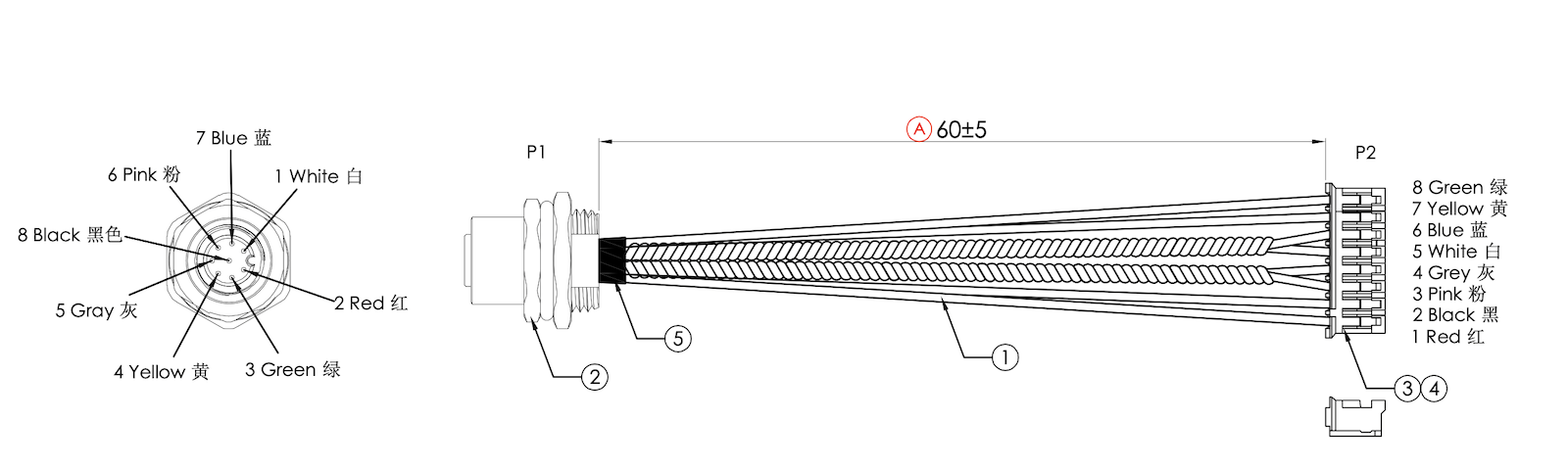
- Cable length: 60 ±5 mm
- Wire gauge: 24 AWG
- M12 8-pin connector, A-coded
M12 connectors
The standard M12 connectors are IP67 waterproof (connected or not), 12 mm in diameter, and have 8 pins or 4 pins. However, M12 connectors are available from 2 pin to 17 pins. The connectors with smaller numbers of pins often have higher voltage and current ratings.
The panel-mount 8-pin connector on the Monitor One is female, with the following pinout:
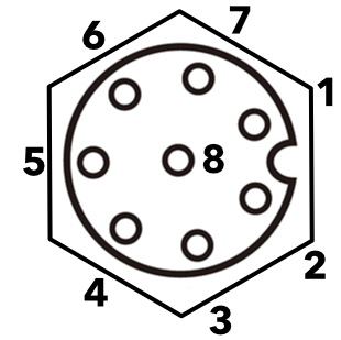
Looking at the bulkhead connector from outside the enclosure
The panel mount M12 8-pin connector fits in the following hole in the enclosure:
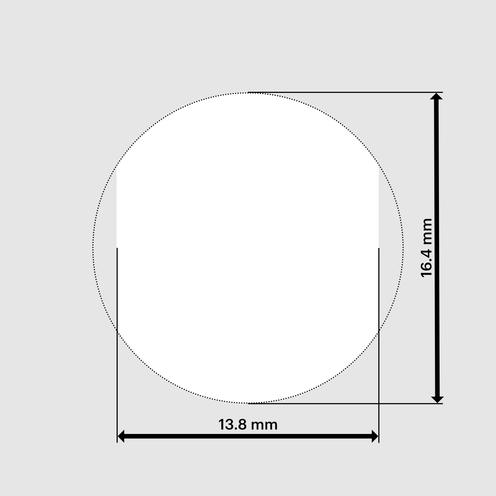
See M12 connector ratings below for voltage and current limits for this connector.
GPIO
| Pin Name | Description | SoM Pin | MCU |
|---|---|---|---|
| NFC1_PERIPH_INT | Peripheral interrupt (active low) | 26 | P0.09 |
| NFC2_VIN_EN | GPIO (used for relay on I/O Card) | 27 | P0.10 |
| RX / D9 | Serial1 RX, GPIO D9, PWM, Wire3 SDA | 71 | P0.08 |
| TSOM_A2_BUTTON / D2 | External user button, A2 Analog in, GPIO D2, PWM | 57 | P0.28 |
| TSOM_A3_BATT_TEMP / D3 | Battery temperature sensor, A3 Analog in, GPIO D3, PWM | 58 | P0.30 |
| TSOM_A4 / D4 | A4 Analog in, GPIO D4, PWM, SPI MOSI | 41 | P0.31 |
| TSOM_A5 / D5 | A5 Analog in, GPIO D5, PWM, SPI MISO | 40 | P0.29 |
| TSOM_A6 / D6 | A6 Analog in, GPIO D6, PWM, SPI (SCK) | 39 | P0.04 |
| TSOM_A7 / D7 | A7 Analog in, GPIO D7, PWM, SPI SS, WKP | 38 | P0.05 |
| TX / D8 | Serial1 TX, GPIO D8, PWM, Wire3 SCL | 72 | P0.06 |
- On the Monitor One, pins A0 and A1 are used in I2C mode by the user RGB LED temperature sensor. Pins A0 and A1 cannot be used as GPIO.
- On the Monitor One, you should not use A2 and A3 as GPIO or analog inputs as they are used by the external user button and battery temperature thermistor.
- All GPIO are 3.3V and are not 5V tolerant.
When using the I/O Card:
| Pin | Direction | Function |
|---|---|---|
| A4 | Output | Direction control for RS485 |
| A5 | Digital Input | Slow signal input, optoisolated, 12V to 24V = HIGH |
| A6 | Analog Input | Analog input, 0-10V, 10V=4095 |
| A7 | Analog Input | 4-20mA current loop input |
| NFC_PIN2 | Output | Relay coil, HIGH = energized |
ADC
| Pin Name | Description | Interface | SoM Pin | MCU |
|---|---|---|---|---|
| TSOM_A2_BUTTON / D2 | External user button, A2 Analog in, GPIO D2, PWM | ADC4 | 57 | P0.28 |
| TSOM_A3_BATT_TEMP / D3 | Battery temperature sensor, A3 Analog in, GPIO D3, PWM | ADC6 | 58 | P0.30 |
| TSOM_A4 / D4 | A4 Analog in, GPIO D4, PWM, SPI MOSI | ADC7 | 41 | P0.31 |
| TSOM_A5 / D5 | A5 Analog in, GPIO D5, PWM, SPI MISO | ADC5 | 40 | P0.29 |
| TSOM_A6 / D6 | A6 Analog in, GPIO D6, PWM, SPI (SCK) | ADC2 | 39 | P0.04 |
| TSOM_A7 / D7 | A7 Analog in, GPIO D7, PWM, SPI SS, WKP | ADC3 | 38 | P0.05 |
- On the Monitor One, you should not use A2 and A3 as analog inputs as they are used by the external user button and battery temperature thermistor.
SPI
| Pin Name | Description | Interface | SoM Pin | MCU |
|---|---|---|---|---|
| TSOM_A4 / D4 | A4 Analog in, GPIO D4, PWM, SPI MOSI | SPI (MOSI) | 41 | P0.31 |
| TSOM_A5 / D5 | A5 Analog in, GPIO D5, PWM, SPI MISO | SPI (MISO) | 40 | P0.29 |
| TSOM_A6 / D6 | A6 Analog in, GPIO D6, PWM, SPI (SCK) | SPI (SCK) | 39 | P0.04 |
- Any available GPIO can be used as a SPI CS/SS pin.
I2C
| Pin Name | Description | Interface | SoM Pin | MCU |
|---|---|---|---|---|
| RX / D9 | Serial1 RX, GPIO D9, PWM, Wire3 SDA | Wire3 (SDA) | 71 | P0.08 |
| TSOM_A0_SDA / D0 | Wire SDA | Wire (SDA) | 55 | P0.03 |
| TSOM_A1_SCL / D1 | Wire SCL | Wire (SCL) | 56 | P0.02 |
| TX / D8 | Serial1 TX, GPIO D8, PWM, Wire3 SCL | Wire3 (SCL) | 72 | P0.06 |
- On the Monitor One, pins A0 and A1 are used in I2C mode by the user RGB LED and temperature sensor. Pins A0 and A1 cannot be used as GPIO.
- On the Monitor One (and Tracker SoM),
WireandWire3share the same I2C peripheral and cannot be used at the same time. - On the Monitor One (and Tracker SoM),
Wire3andSerial1share the same pins and only one can be used at a time. - I2C is 3.3V only and is not 5V tolerant.
- There are 4.7K pull-up resistors on
TSOM_A0_SDAandTSOM_A1_SCLto 3.3V on the base board.
Serial (UART)
| Pin Name | Description | Interface | SoM Pin | MCU |
|---|---|---|---|---|
| RX / D9 | Serial1 RX, GPIO D9, PWM, Wire3 SDA | Serial1 RX | 71 | P0.08 |
| TX / D8 | Serial1 TX, GPIO D8, PWM, Wire3 SCL | Serial1 TX | 72 | P0.06 |
- On the Monitor One (and Tracker SoM),
Wire3andSerial1share the same pins and only one can be used at a time. - Hardware flow control is not available on the Monitor One.
- Serial pins are 3.3V only and are not 5V tolerant.
- Additional interface chips are required for other serial standards such as RS232 and RS485.
PWM
| Pin Name | Description | Interface | SoM Pin | MCU |
|---|---|---|---|---|
| RX / D9 | Serial1 RX, GPIO D9, PWM, Wire3 SDA | PWM2 | 71 | P0.08 |
| TSOM_A2_BUTTON / D2 | External user button, A2 Analog in, GPIO D2, PWM | PWM0 | 57 | P0.28 |
| TSOM_A3_BATT_TEMP / D3 | Battery temperature sensor, A3 Analog in, GPIO D3, PWM | PWM0 | 58 | P0.30 |
| TSOM_A4 / D4 | A4 Analog in, GPIO D4, PWM, SPI MOSI | PWM1 | 41 | P0.31 |
| TSOM_A5 / D5 | A5 Analog in, GPIO D5, PWM, SPI MISO | PWM1 | 40 | P0.29 |
| TSOM_A6 / D6 | A6 Analog in, GPIO D6, PWM, SPI (SCK) | PWM1 | 39 | P0.04 |
| TSOM_A7 / D7 | A7 Analog in, GPIO D7, PWM, SPI SS, WKP | PWM1 | 38 | P0.05 |
| TX / D8 | Serial1 TX, GPIO D8, PWM, Wire3 SCL | PWM2 | 72 | P0.06 |
- On the Monitor One, you should not use A2 and A3 as PWM outputs as they are used by the external user button and battery temperature thermistor.
- All pins on the same hardware timer (PWM0, PWM1, or PWM2) must share the same frequency but can have different duty cycles.
CAN
| Pin Name | Description | Interface | SoM Pin |
|---|---|---|---|
| CAN_5V | 5V power out, 0.8A maximum. Can be controlled by software. | CAN_5V | 66 |
| CAN_N | CAN Data- or CANL | CAN_N | 64 |
| CAN_P | CAN Data+ or CANH | CAN_P | 65 |
The CAN transceiver is included on the Tracker SoM. However if you implement CAN on your expansion card, you will probably want to add protection circuitry. This circuit is present on the Monitor One CAN expansion card and also on the Tracker One.
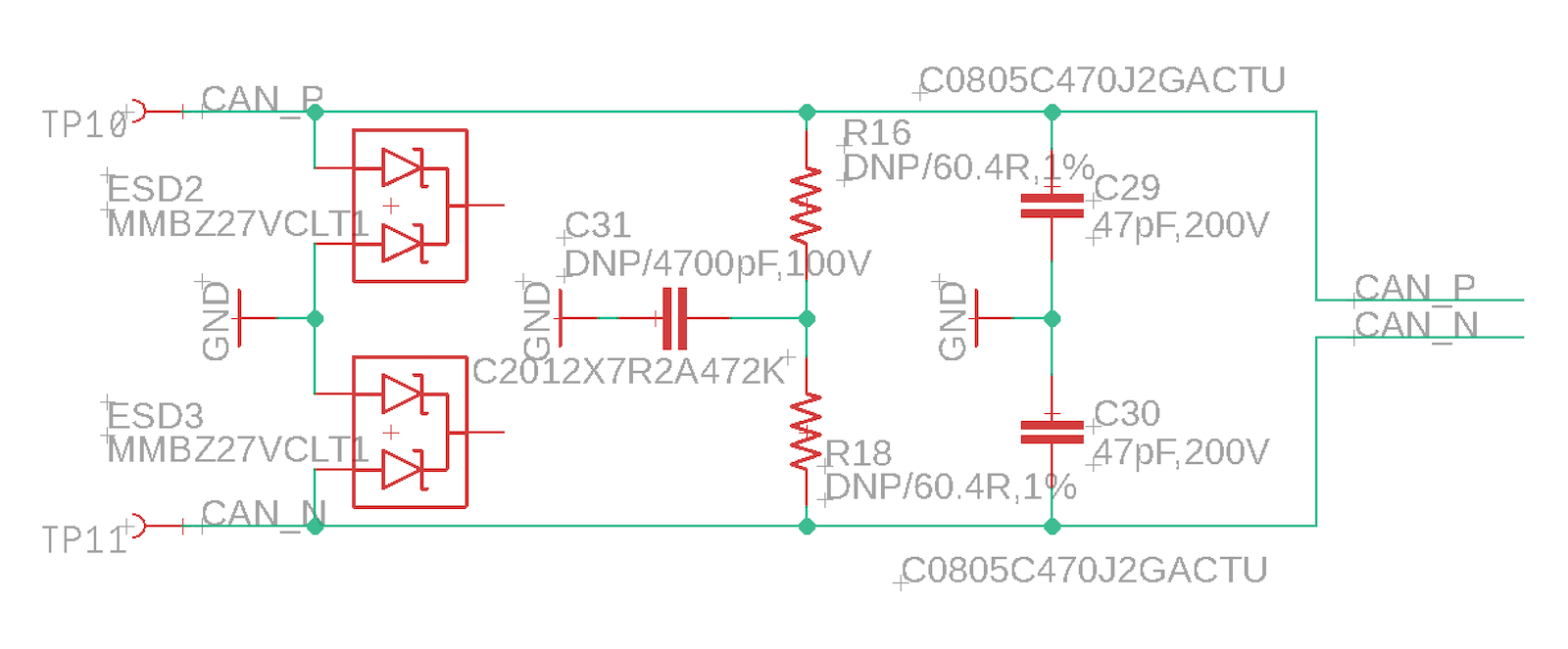
Note that the two 60.4 ohm resistors are DNP (do not populate). If populated, these provide the 120 ohm CAN termination, if you need it in your design.
All expansion card pins
| Pin | Pin Name | Description | MCU |
|---|---|---|---|
| 1 | GNSS_PULSE | GNSS time pulse output. Can be used for a GPS fix LED. | |
| 2 | NC | ||
| 3 | NC | ||
| 4 | NC | ||
| 5 | NC | ||
| 6 | NC | ||
| 7 | NC | ||
| 8 | NC | ||
| 9 | NFC2_VIN_EN | GPIO (used for relay on I/O Card) | P0.10 |
| 10 | NFC1_PERIPH_INT | Peripheral interrupt (active low) | P0.09 |
| 11 | TSOM_MODE | MODE button (active low) | P1.13 |
| 12 | TSOM_RESET | RESET button (active low) | |
| 13 | TSOM_A7 / D7 | A7 Analog in, GPIO D7, PWM, SPI SS, WKP | P0.05 |
| 14 | TSOM_A6 / D6 | A6 Analog in, GPIO D6, PWM, SPI (SCK) | P0.04 |
| 15 | TSOM_A5 / D5 | A5 Analog in, GPIO D5, PWM, SPI MISO | P0.29 |
| 16 | TSOM_A4 / D4 | A4 Analog in, GPIO D4, PWM, SPI MOSI | P0.31 |
| 17 | GND | Ground. | |
| 18 | 3V3 | 3.3V out, 1000 mA maximum including nRF52 and other peripherals. | |
| 19 | RUN | Pull low to disable LTC7103 regulator. Has 100K pull-up to VIN. | |
| 20 | PGOOD | LTC7103 regulator open drain power good output. Pulled low when regulator is not in regulation. | |
| 21 | GND | Ground. | |
| 22 | GND | Ground. | |
| 23 | VIN | Power input, 6 - 90 VDC | |
| 24 | VIN | Power input, 6 - 90 VDC | |
| 25 | LI+ | Connect to Li-Po battery. Can power the device or be recharged by VIN or VBUS. | |
| 26 | GND | Ground. | |
| 27 | TSOM_USB_VBUS | nRF52 USB power input. Can be used as a 5V power supply instead of VIN. | |
| 28 | GND | Ground. | |
| 29 | TSOM_VIN | Tracker SoM power input 5V-12V DC. | |
| 30 | GND | Ground. | |
| 31 | 5V | 5V power output when powered by VIN or USB | |
| 32 | GND | Ground. | |
| 33 | TSOM_A0_SDA / D0 | Wire SDA | P0.03 |
| 34 | TSOM_A1_SCL / D1 | Wire SCL | P0.02 |
| 35 | TSOM_A2_BUTTON / D2 | External user button, A2 Analog in, GPIO D2, PWM | P0.28 |
| 36 | TSOM_A3_BATT_TEMP / D3 | Battery temperature sensor, A3 Analog in, GPIO D3, PWM | P0.30 |
| 37 | GND | Ground. | |
| 38 | CAN_N | CAN Data- or CANL | |
| 39 | CAN_P | CAN Data+ or CANH | |
| 40 | CAN_5V | 5V power out, 0.8A maximum. Can be controlled by software. | |
| 41 | GND | Ground. | |
| 42 | TSOM_USB_N | nRF52 MCU USB interface D-. | |
| 43 | TSOM_USB_P | nRF52 MCU USB interface D+. | |
| 44 | GND | Ground. | |
| 45 | RX / D9 | Serial1 RX, GPIO D9, PWM, Wire3 SDA | P0.08 |
| 46 | TX / D8 | Serial1 TX, GPIO D8, PWM, Wire3 SCL | P0.06 |
| 47 | RTC_BAT | RTC/Watchdog battery +. Connect to GND if not using. | |
| 48 | RTC_EXTI | RTC EXTI. Can use as a wake button. Has 100K weak pull-up to 3V3. |
- Pins 9 and 10 have NFC in the name from the Tracker SoM, however NFC cannot be used on the Monitor One as the pins must be used as
VIN_ENandPERIPH_INT.
I/O characteristics
The GPIO pins on the expansion connector have the following specifications, from the nRF52840 datasheet:
| Symbol | Parameter | Min | Typ | Max | Unit |
|---|---|---|---|---|---|
| VIH | Input high voltage | 0.7 xVDD | VDD | V | |
| VIL | Input low voltage | VSS | 0.3 xVDD | V | |
| VOH,SD | Output high voltage, standard drive, 0.5 mA, VDD ≥1.7 | VDD - 0.4 | VDD | V | |
| VOH,HDH | Output high voltage, high drive, 5 mA, VDD >= 2.7 V | VDD - 0.4 | VDD | V | |
| VOH,HDL | Output high voltage, high drive, 3 mA, VDD >= 1.7 V | VDD - 0.4 | VDD | V | |
| VOL,SD | Output low voltage, standard drive, 0.5 mA, VDD ≥1.7 | VSS | VSS + 0.4 | V | |
| VOL,HDH | Output low voltage, high drive, 5 mA, VDD >= 2.7 V | VSS | VSS + 0.4 | V | |
| VOL,HDL | Output low voltage, high drive,3 mA, VDD >= 1.7 V | VSS | VSS + 0.4 | V | |
| IOL,SD | Current at VSS+0.4 V, output set low, standard drive, VDD≥1.7 | 1 | 2 | 4 | mA |
| IOL,HDH | Current at VSS+0.4 V, output set low, high drive, VDD >= 2.7V | 6 | 10 | 15 | mA |
| IOL,HDL | Current at VSS+0.4 V, output set low, high drive, VDD >= 1.7V | 3 | mA | ||
| IOH,SD | Current at VDD-0.4 V, output set high, standard drive, VDD≥1.7 | 1 | 2 | 4 | mA |
| IOH,HDH | Current at VDD-0.4 V, output set high, high drive, VDD >= 2.7V | 6 | 9 | 14 | mA |
| IOH,HDL | Current at VDD-0.4 V, output set high, high drive, VDD >= 1.7V | 3 | mA | ||
| RPU | Pull-up resistance | 11 | 13 | 16 | kΩ |
| RPD | Pull-down resistance | 11 | 13 | 16 | kΩ |
- GPIO default to standard drive (2mA) but can be reconfigured to high drive (9mA) in Device OS 2.0.0 and later using the
pinSetDriveStrength()function.
GPIO and port leakage current warning
Be careful when you are connecting GPIO or ports such as serial that may have power when the Monitor One is not powered, such as when using shipping mode.
If you have current flowing into GPIO or ports of the nRF52840 when it is powered down, it can cause it to enter a state where it cannot be reawaked without removing all power from it, including the internal LiPo battery. This may be difficult if you've sealed your Monitor One enclosure.
The Tracker One has a TI TS3A5018 Quad SPDT Analog Switch on the three GPIO pins (A3, D9/RX/SDA, D8/TX/SCL) to prevent this. The switch is normally open, and is closed when the CAN_5V is powered. By default, Tracker Edge enables CAN_5V when in normal operating mode and turns it off during sleep, however this behavior can be changed by using enableIoCanPower() and enableIoCanPowerSleep() in the TrackerConfiguration object.
The Tracker One circuit looks like this, and you may want to implement something similar if you are in a scenario where you have externally powered peripherals.
This is not necessary if your external peripherals are powered by 3V3 or CAN_5V.
VIN disable
By default, if power is applied at the VIN pin it will be used to power the Monitor One and charge the built-in battery.
If you are supplying VIN from another, larger battery pack, and want to be able to disconnect the VIN power supply to minimize current loss, you can do so using the following circuit in lieu of using NFC2 as the relay pin, as the I/O Card does.
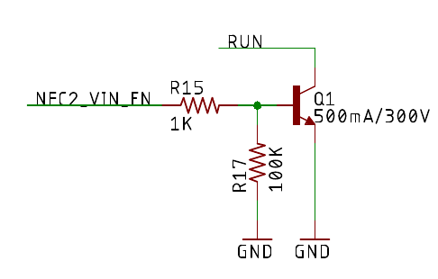
By disconnecting the VIN power supply, it reduces the current used by the VIN and PMIC voltage regulators. The Monitor One can still be powered by its internal LiPo battery. This is particularly advantageous if the Monitor One is in sleep mode while VIN is disconnected as the power supply loss will be large compared to the very low sleep current in this scenario.
GPIO and Ports vs. Tracker One
| Pin | Monitor One | Tracker One |
|---|---|---|
| A0 | I2C SDA1 | Internal Thermistor |
| A1 | I2C SCL1 | User Button (not accessible) |
| A2 | External Button | GNSS lock indicator |
| A3 | Battery Temperature | M8 Analog in, GPIO |
| A4 | Analog in, GPIO, PWM, SPI MOSI1 | Not available |
| A5 | Analog in, GPIO, PWM, SPI MISO1 | Not available |
| A6 | Analog in, GPIO, PWM, SPI SCK1 | Not available |
| A7 | Analog in, GPIO, PWM, SPI SS, WKP | Not available |
| TX | MCU serial TX, GPIO D8, Wire3 SCL1 | MCU serial TX, GPIO D8, Wire3 SCL |
| RX | MCU serial RX, GPIO D9, Wire3 SDA1 | MCU serial RX, GPIO D9, Wire3 SDA |
1Available on expansion card connector (internal)
- On the Monitor One, the expansion card connector allows the use the I2C, Serial, and SPI at the same time
- On the Tracker One, you must choose between using the M8 for either serial or I2C. SPI is not available.
Tracker feature comparison
| Tracker SoM | Tracker One | Monitor One | |
|---|---|---|---|
| Style | SMD Module | All-in-one | All-in-one |
| Enclosure | Your design | Included | Included |
| MCU | nRF52840 | nRF52840 | nRF52840 |
| CPU Speed | 64 MHz | 64 MHz | 64 MHz |
| Maximum user binary | 256 KB | 256 KB | 256 KB |
| Flash file system6 | 4 MB | 4 MB | 4 MB |
| Base board | Included | Included | Included |
| Expansion connector | Your design | M8 8-pin | Multiple options |
| GNSS Antenna | Your design | Internal | Int/Ext2 |
| Cellular Antenna | Your design | Internal | Int/Ext2 |
| Wi-Fi geolocation antenna | Your design | Internal | Internal |
| BLE Antenna | Your design | Internal | Internal4 |
| NFC Tag | Your design | Included | n/a |
| USB Connector | Your design | USB C | Micro B (Int)3 |
| System RGB LED | Your design | Included | Included |
| External user button | Your design | ✓ | |
| User RGB LEDs | 2 | ||
| SETUP and MODE buttons | Your design | Inside Enclosure | Inside Enclosure |
| External power | 3.9 - 17 VDC | 6 - 30 VDC | 6 - 30 VDC |
| SPI | ✓ | n/a | Expansion card |
| I2C | ✓ | M8 | Expansion card |
| Serial | ✓ | M8 | Expansion card |
| Internal temperature sensor | Your design | ✓ | ✓ |
| Battery temperature sensor | n/a | n/a | ✓ |
| Controlling charging by temperature | Your design | In software | In software |
1On the Tracker One, the M8 can be configured for GPIO, I2C (SDA and SCL), or Serial (RX and TX) on two pins.
2Both internal and external GNSS and cellular are supported by physically changing the antenna connector inside the enclosure.
3There is no external MCU USB connector on the Monitor One.
4The Monitor One uses the Tracker SoM BLE chip antenna on the board and does not include a separate BLE antenna, but one could be added using the BLE U.FL connector.
6A small portion of the flash file system is used by the system, and a configurable portion can be used for store and forward, to optionally allow location publishes to be saved when the device is offline to be uploaded later. The remainder of the flash file system can be used by user applications.
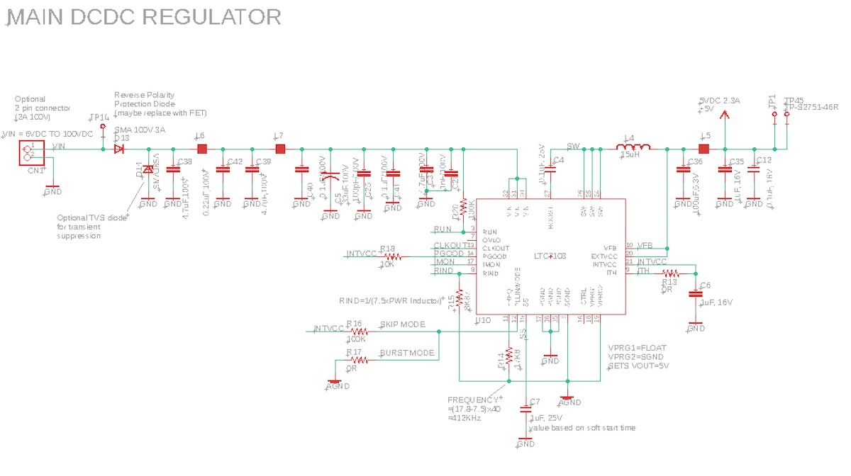
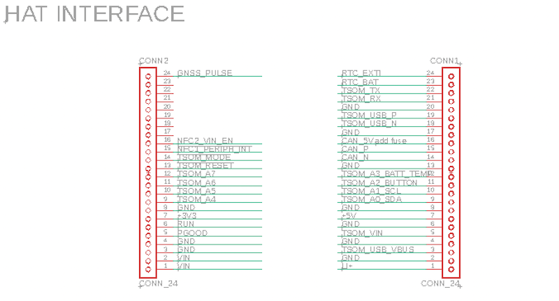
Schematics
Mechanical specifications
Operating temperature
| Parameter | Minimum | Maximum | Units |
|---|---|---|---|
| Operating temperature | -10 | 60 | °C |
| Battery charging enabled | 0 | 40 | °C |
Dimensions and weight
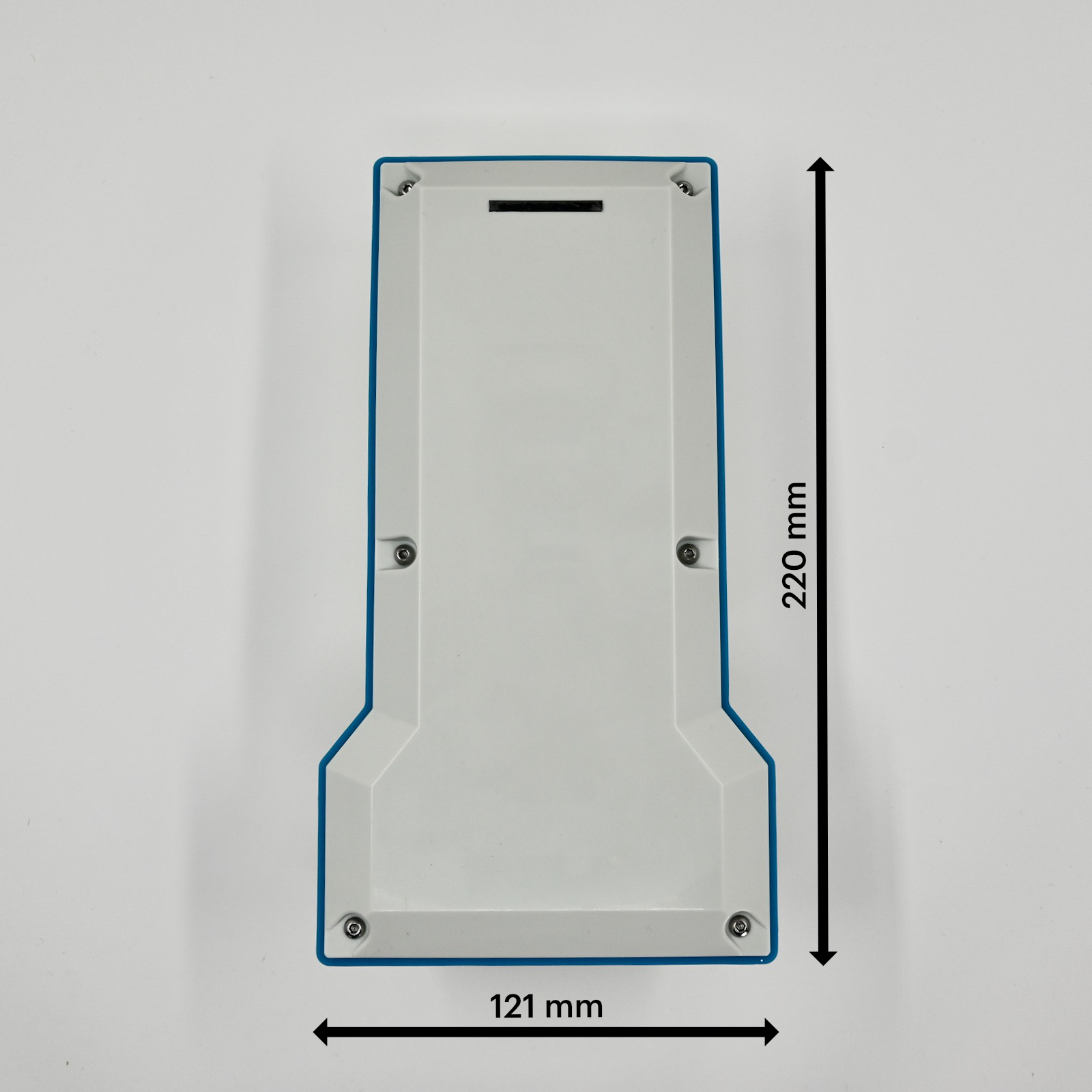
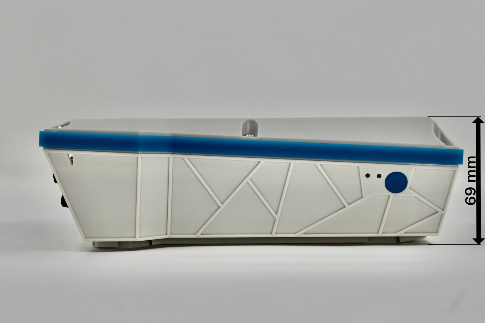
| Dimensions | Metric | SAE |
|---|---|---|
| Width | 121 mm | 4 3/4" |
| Height | 220 mm | 8 5/8" |
| Depth | 69 mm | 2 11/16" |
| Weight | 775 g | 27.3 oz |
Dimensions for top cover artwork
Power consumption
To be provided at a later date.
Battery specifications
- Lithium-ion cylindrical rechargeable battery
- Model: 18650-4P
- Description: Single cell with PCM
- Battery capacity: 12200 mAh
- Batter voltage : 3.7 VDC (nominal)
- Manufacturer: Guangdong Zhaoeng Technology Co., Ltd. (Guangdong, China)
- Datasheet
M12 connector ratings
The maximum ratings for the M12 bulkhead connectors and flying lead connectors are:
- M12 8pin: 30V AC/DC, 2A
- M12 4pin: 250V AC/DC, 4A
The connectors are rated IP67 in both connected and unconnected state.
Country compatibility
To be provided at a later date.
| Country | Model | Technologies | Carriers |
|---|---|---|---|
| Albania | MON524 | 2G, 3G, 4G | Eagle, Telekom, Vodafone |
| Algeria | MON524 | 2G, 3G, 4G | Mobilis, Ooredoo |
| Aruba | MON524 | 2G, 3G, 4G | Setar |
| Australia | MON524 | 4G | Optus, Telstra, Vodafone |
| Austria | MON524 | 2G, 4G | 3 (Drei), A1, T-Mobile |
| Bahrain | MON524 | 2G, 4G | Zain |
| Bangladesh | MON524 | 2G, 3G, 4G | Bangalink, GrameenPhone |
| Belarus | MON524 | 2G, 3G, 4G | A1 |
| Belgium | MON524 | 2G, 4G | Base, Orange, Proximus |
| Bosnia and Herzegovina | MON524 | 2G, 3G | HT Eronet |
| Botswana | MON524 | 2G, 3G, 4G | BeMobile |
| Brunei | MON524 | 3G, 4G | DST |
| Bulgaria | MON524 | 2G, 3G | A1, Telenor, Vivacom |
| Burkina Faso | MON524 | 2G, 3G, 4G | Orange |
| Cabo Verde | MON524 | 2G, 3G, 4G | CVMóvel, Unitel T+ |
| Cambodia | MON524 | 2G, 3G | Metfone |
| Canada | MON404 | M1 | Bell Mobility, Rogers Wireless, Telus |
| Chad | MON524 | 2G, 3G, 4G | Airtel |
| Chile | MON524 | 3G, 4G | Claro, Entel, Movistar |
| Congo (Brazzaville) | MON524 | 2G, 3G, 4G | Airtel |
| Congo (Kinshasa) | MON524 | 2G, 3G, 4G | Airtel |
| Côte d'Ivoire | MON524 | 2G, 3G | MTN |
| Croatia | MON524 | 2G, 3G, 4G | Hrvatski Telekom, Tele2 |
| Cyprus | MON524 | 2G, 3G, 4G | MTN, PrimeTel |
| Czechia | MON524 | 2G, 4G | O2, T-Mobile, Vodafone |
| Denmark | MON524 | 2G, 4G | 3 (Tre), TDC, Telenor, Telia |
| Egypt | MON524 | 2G, 3G, 4G | Etisalat, Orange |
| Estonia | MON524 | 2G, 3G, 4G | Elisa, Tele2, Telia |
| eSwatini | MON524 | 2G, 3G, 4G | MTN |
| Ethiopia | MON524 | 2G, 3G, 4G | Ethio Telecom |
| Faroe Islands | MON524 | 2G, 3G | Faroese Telecom, Vodafone |
| Finland | MON524 | 2G, 4G | DNA, Elisa, Telia |
| France | MON524 | 2G, 3G, 4G | Bouygues, Free Mobile, Orange, SFR |
| French Guiana | MON524 | 2G, 3G | Digicel |
| Gabon | MON524 | 2G, 3G, 4G | Airtel |
| Germany | MON524 | 2G, 4G | O2, Telekom, Vodafone |
| Ghana | MON524 | 2G, 3G, 4G | AirtelTigo, MTN, Vodafone |
| Gibraltar | MON524 | 2G, 3G, 4G | Gibtel |
| Greece | MON524 | 2G, 4G | Cosmote, Vodafone, Wind |
| Guinea | MON524 | 2G, 3G, 4G | MTN |
| Guinea-Bissau | MON524 | 2G, 3G, 4G | MTN |
| Guyana | MON524 | 2G | Digicel |
| Hong Kong | MON524 | 3G, 4G | CMHK, CSL, SmarTone |
| Hungary | MON524 | 2G, 3G, 4G | Magyar Telekom, Telenor, Vodafone |
| Iceland | MON524 | 4G | Nova, Siminn, Vodafone |
| Indonesia | MON524 | 2G, 4G | Indosat, Telkomsel, XL Axiata |
| Ireland | MON524 | 2G, 3G, 4G | 3 (Tre), Meteor, O2, Vodafone |
| Israel | MON524 | 4G | Hot Mobile, Orange, Pelephone |
| Italy | MON524 | 2G, 4G | TIM, Vodafone, Wind |
| Jordan | MON524 | 2G, 3G, 4G | Zain |
| Kazakhstan | MON524 | 2G, 3G, 4G | Beeline, K-Cell |
| Kenya | MON524 | 2G, 3G, 4G | Airtel |
| Kuwait | MON524 | 2G, 3G, 4G | Viva, Zain |
| Latvia | MON524 | 2G, 4G | Bite, LMT, Tele2 |
| Liechtenstein | MON524 | 2G, 3G, 4G | Mobilkom, Orange |
| Lithuania | MON524 | 2G, 4G | Bite, Omnitel, Tele2 |
| Luxembourg | MON524 | 2G, 4G | Orange, POST, Tango |
| Macao | MON524 | 3G, 4G | CTM |
| Madagascar | MON524 | 2G, 3G, 4G | Airtel |
| Malawi | MON524 | 2G, 3G, 4G | Airtel |
| Malaysia | MON524 | 2G, 4G | Celcom, DiGi, Maxis |
| Malta | MON524 | 2G, 3G, 4G | Go Mobile, Vodafone |
| Mexico | MON404 | M1 | AT&T, Telcel |
| Moldova | MON524 | 2G, 3G, 4G | Moldcell, Orange |
| Mongolia | MON524 | 2G, 3G | Mobicom, Unitel |
| Montenegro | MON524 | 2G, 3G, 4G | Mtel, T-Mobile, Telenor |
| Morocco | MON524 | 2G, 3G, 4G | Inwi, Medi Telecom |
| Mozambique | MON524 | 2G, 3G, 4G | Vodacom |
| Myanmar | MON524 | 2G, 3G, 4G | MPT, Telenor |
| Namibia | MON524 | 2G, 3G, 4G | Telecom Namibia |
| Netherlands | MON524 | 2G, 3G, 4G | KPN, T-Mobile, Vodafone |
| New Zealand | MON524 | 4G | 2degrees, Spark, Vodafone |
| Nigeria | MON524 | 2G, 3G, 4G | 9mobile, Airtel, Glo, MTN |
| Norway | MON524 | 2G, 3G, 4G | TDC, Telenor, Telia |
| Pakistan | MON524 | 2G, 3G, 4G | Mobilink, Telenor, Ufone, Warid |
| Palestine | MON524 | 2G, 3G | Jawwal |
| Papua New Guinea | MON524 | 2G, 3G | bmobile |
| Poland | MON524 | 2G, 3G, 4G | Orange, Play, Plus, T-Mobile |
| Portugal | MON524 | 2G, 3G, 4G | NOS, TMN, Vodafone |
| Qatar | MON524 | 2G, 4G | Ooredoo, Vodafone |
| Romania | MON524 | 2G, 4G | Orange, Telekom Romania, Vodafone |
| Rwanda | MON524 | 2G, 3G | Airtel, MTN |
| Serbia | MON524 | 2G, 3G, 4G | Telenor, VIP |
| Seychelles | MON524 | 2G, 3G, 4G | Airtel |
| Sint Maarten | MON524 | 2G, 3G | TelCell |
| Slovakia | MON524 | 2G, 4G | O2, Orange, Telekom |
| Slovenia | MON524 | 2G, 3G, 4G | A1, Mobitel |
| South Africa | MON524 | 2G, 3G, 4G | Cell C, MTN, Vodacom |
| South Korea | MON524 | 3G, 4G | KT, LG U+, SK Telecom |
| South Sudan | MON524 | 2G, 3G | MTN |
| Spain | MON524 | 2G, 3G, 4G | Orange, Telefonica, Vodafone, Yoigo |
| Sri Lanka | MON524 | 2G, 4G | Dialog, Mobitel |
| Suriname | MON524 | 2G, 3G | Telesur |
| Sweden | MON524 | 2G, 4G | 3 (Tre), Tele2, Telenor, Telia |
| Switzerland | MON524 | 3G, 4G | Salt, Sunrise, Swisscom |
| Taiwan | MON524 | 4G | Chunghwa, FarEasTone, T Star, Taiwan Mobile |
| Tanzania | MON524 | 2G, 3G, 4G | Airtel |
| Thailand | MON524 | 2G, 3G, 4G | AIS, DTAC, True Move |
| Tunisia | MON524 | 2G, 3G, 4G | Orange Tunisie, Tunisie Telecom |
| Uganda | MON524 | 2G, 3G, 4G | Africell, Airtel, MTN |
| United Kingdom | MON524 | 2G, 4G | 3, EE, O2, Vodafone |
| United States | MON404 | M1 | AT&T, T-Mobile (USA), Verizon7 |
| Vietnam | MON524 | 3G, 4G | MobiFone, Viettel, Vinaphone |
| Zambia | MON524 | 2G, 3G, 4G | Airtel |
7Verizon in the United States is only supported on enterprise plans.
Ordering information
| SKU | Description | Region | Modem | EtherSIM | Lifecycle | Replacement |
|---|---|---|---|---|---|---|
| MON404E01C01KIT | Monitor One LTE CAT-M1 (NorAm, EtherSIM), Particle Transparent Enclosure, IO Card, Developer Edition [x1] | NORAM | BG96-MC | ✓ | GA | |
| MON524E01C01KIT | Monitor One LTE CAT-1/3G/2G (Europe, EtherSIM), Particle Transparent Enclosure, IO Card, Developer Edition [x1] | EMEAA | EG91-EX | ✓ | GA | |
| MON404E02C01KIT | Monitor One LTE CAT-M1 (NorAm, EtherSIM), Particle Blue Enclosure, IO Card, Developer Edition [x1] | NORAM | BG96-MC | ✓ | In development |
†EMEAA: Selected countries in Europe, Middle East, Africa, and Asia, including Australia and New Zealand. See the cellular carrier list for more information.
Certification
FCC interference statement
This device complies with part 15 of the FCC Rules. Operation is subject to the following two conditions: (1) This device may not cause harmful interference, and (2) this device must accept any interference received, including interference that may cause undesired operation.
This device complies with Part 15, Part 15.247 of the FCC Rules. The FCC ID for this device is 2AEMI-MONEHDK.
This device must not be co-located or operating in conjunction with any other antenna or transmitter. This equipment has been tested and found to comply with the limits for a Class B digital device, pursuant to part 15 of the FCC Rules. These limits are designed to provide reasonable protection against harmful interference in a residential installation.
This equipment generates, uses and can radiate radio frequency energy and, if not installed and used in accordance with the instructions, may cause harmful interference to radio communications. However, there is no guarantee that interference will not occur in a particular installation. If this equipment does cause harmful interference to radio or television reception, which can be determined by turning the equipment off and on, the user is encouraged to try to correct the interference by one or more of the following measures:
- Reorient or relocate the receiving antenna.
- Increase the separation between the equipment and receiver.
- Connect the equipment into an outlet on a circuit different from that to which the receiver is connected.
- Consult the dealer or an experienced radio/TV technician for help.
To comply with FCC’s RF radiation exposure limits for general population/uncontrolled exposure, this device must be installed to provide a separation distance of at least 20cm from all persons.
WARNING: Any changes or modifications to this unit not expressly approved by the party responsible for compliance could void the user’s authority to operate the equipment.
This device must not be collocated or operating in conjunction with any other antenna or transmitter.
ISED interference statement
ISED: 20127-MONEHDK
This device complies with Industry Canada license-exempt RSS standard(s). Operation is subject to the following two conditions:
- this device may not cause interference.
- this device must accept any interference, including interference that may cause undesired operation of the device.
Le présent appareil est conforme aux CNR d'Industrie Canada applicables aux appareils radio exempts de licence. L'exploitation est autorisée aux deux conditions suivantes:
- l'appareil ne doit pas produire de brouillage, et
- l'utilisateur de l'appareil doit accepter tout brouillage radioélectrique subi, même si le brouillage est susceptible d'en compromettre le fonctionnement.
This Class B digital apparatus complies with Canadian ICES-003.
Cet appareil numérique de la classe B est conforme à la norme NMB-003 du Canada.
This device and its antenna(s) must not be co-located or operating in conjunction with any other antenna or transmitter, except tested built-in radios.
Cet appareil et son antenne ne doivent pas être situés ou fonctionner en conjonction avec une autre antenne ou un autre émetteur, exception faites des radios intégrées qui ont été testées.
This equipment complies with IC radiation exposure limits set forth for an uncontrolled environment. This equipment should be installed and operated with minimum distance 20cm between the radiator & your body.
Cet équipement est conforme aux limites d'exposition aux rayonnements IC établies pour un environnement non contrôlé. Cet équipement doit être installé et utilisé avec un minimum de 20 cm de distance entre la source de rayonnement et votre corps.
EU declaration of conformity
We, Particle Industries, Inc., declare under our sole responsibility that the product, MON524, to which this declaration relates, is in conformity with RED Directive 2014/53/EU and (EU) 2015/863 RoHS Directive 2011/65/EU (Recast).
The full text of the EU declaration of conformity is available at the following Internet address https://www.particle.io/.
Radiation Exposure Statement: This equipment complies with radiation exposure limits set forth for an uncontrolled environment.
The operating frequency bands and the maximum transmitted power limit are listed below:
- BLE 2402-2480MHz, 10dBm
- Wi-Fi 2.4GHz band 20dBm
- LTE (CAT-1 bands B1 B3 B7 B8 B20 B28), Frequency Ranges: 703-960MHz, 1710-2170MHz, 2550-2690MHz, Max TX Power: 25dBm
- 3G (WCDMA sits on LTE B1, B8), Frequency Ranges: 880-960MHz, 1920-2170 MHz, Max TX Power: 25dBm
- 2G (EGSM900 sits on LTE B8), Frequency Ranges: 880-915MHz, 925-960 MHz, Max TX Power: 35dBm
- 2G (DCS1800 sits on LTE B3), Frequency Ranges: 1710.2-1784.8MHz, 1805.2-1879.8MHz, Max TX Power: 32dBm
United Kingdom
UKCA Conformity:
Radio Equipment Regulations 2017 (S.I. 2017/1206)
Certification documents
FCC (United States) - MON404DE Monitor One Developer Edition NorAm
- FCC ID: 2AEMI-MONEDE
- Part 15B, 746 MHz - 894 MHz
- Part 15C, Digital Transmission System 2.4 GHz
- Part 15B, Part 15 Class B Computing Device Peripheral
- Part 22H, 24E, 27, PCS Licensed Transmitter
- Test report FCC Part 15, Subpart B, Class B
- Test report FCC Part 22
- Test report FCC Part 24
- Test report FCC Part 27
- Test photos, FCC Part 15B
- Test photos, FCC External
- Test photos, FCC Internal
- Test photos, FCC RF Test Setup
ISED (Canada) - MON404 Monitor One Developer Edition NorAm
- ISED: 20127-MONEDE
- Certificate of Conformity
- Test Report RS-130
- Test Report RS-132
- Test Report RS-133
- Test Report RS-139
- ICES-003 Issue 7:2020
- Test photos, ISED ICES003
- Test photos, ISED External
- Test photos, ISED Internal
- Test photos, ISED RF Test Setup
RoHS - MON404 Monitor One Developer Edition NorAm
Product handling
ESD precautions
The Monitor One contains highly sensitive electronic circuitry and is an Electrostatic Sensitive Device (ESD). Handling an module without proper ESD protection may destroy or damage it permanently. Proper ESD handling and packaging procedures must be applied throughout the processing, handling and operation of any application that incorporates the module. ESD precautions should be implemented on the application board where the B series is mounted. Failure to observe these precautions can result in severe damage to the module!
Battery warnings
CAUTION
RISK OF EXPLOSION IF BATTERY IS REPLACED BY AN INCORRECT TYPE. DISPOSE OF USED BATTERIES ACCORDING TO THE INSTRUCTIONS.
- Replacement of a battery with an incorrect type that can defeat a safeguard.
- Disposal of a battery into fire or a hot oven, or mechanically crushing or cutting of a battery, that can result in an explosion.
- Leaving a battery in an extremely high temperature surrounding environment that can result in an explosion or the leakage of flammable liquid or gas.
- A battery subjected to extremely low air pressure that may result in an explosion or the leakage of flammable liquid or gas.
This symbol indicates DC voltage: 
Disposal

This device must be treated as Waste Electrical & Electronic Equipment (WEEE) when disposed of.
Any WEEE marked waste products must not be mixed with general household waste, but kept separate for the treatment, recovery and recycling of the materials used. For proper treatment, recovery and recycling; please take all WEEE marked waste to your Local Authority Civic waste site, where it will be accepted free of charge. If all consumers dispose of Waste Electrical & Electronic Equipment correctly, they will be helping to save valuable resources and preventing any potential negative effects upon human health and the environment of any hazardous materials that the waste may contain.
Revision history
| Date | Author | Comments |
|---|---|---|
| 2022-10-24 | RK | For internal review only |
| 2023-02-14 | RK | Updated diagrams |
| 2023-06-07 | RK | Numerous updates |
| 2023-06-13 | RK | Add Prototype Card, update card names |
| 2023-06-20 | RK | Added photos |
| 2023-07-17 | RK | Link to quick start, screw sizes |
| 2023-09-01 | RK | Added battery specifications |
| 2023-09-08 | RK | Added schematics |
| 2023-10-18 | RK | Added FCC and ISED |
| 2023-11-14 | RK | Renamed RS485 pins A and B instead of P and N |
| 2024-01-29 | RK | Add battery warnings |
| 2024-04-02 | RK | Changed power supply specification from 2A to 12W |
| 2024-04-23 | RK | Added links to certification documents |
| 2024-04-29 | RK | Updated EU certification band information |
| 2024-05-14 | RK | Added voltage and current limits for M12 connectors |
| 2024-08-08 | RK | Wire and Wire3 share the same I2C peripheral, it was reversed in the I2C section |
| 2025-06-18 | RK | Corrected the ADC values for reading the 4-20mA current loop input on the I/O card. |