
M-HAT datasheet (preview)
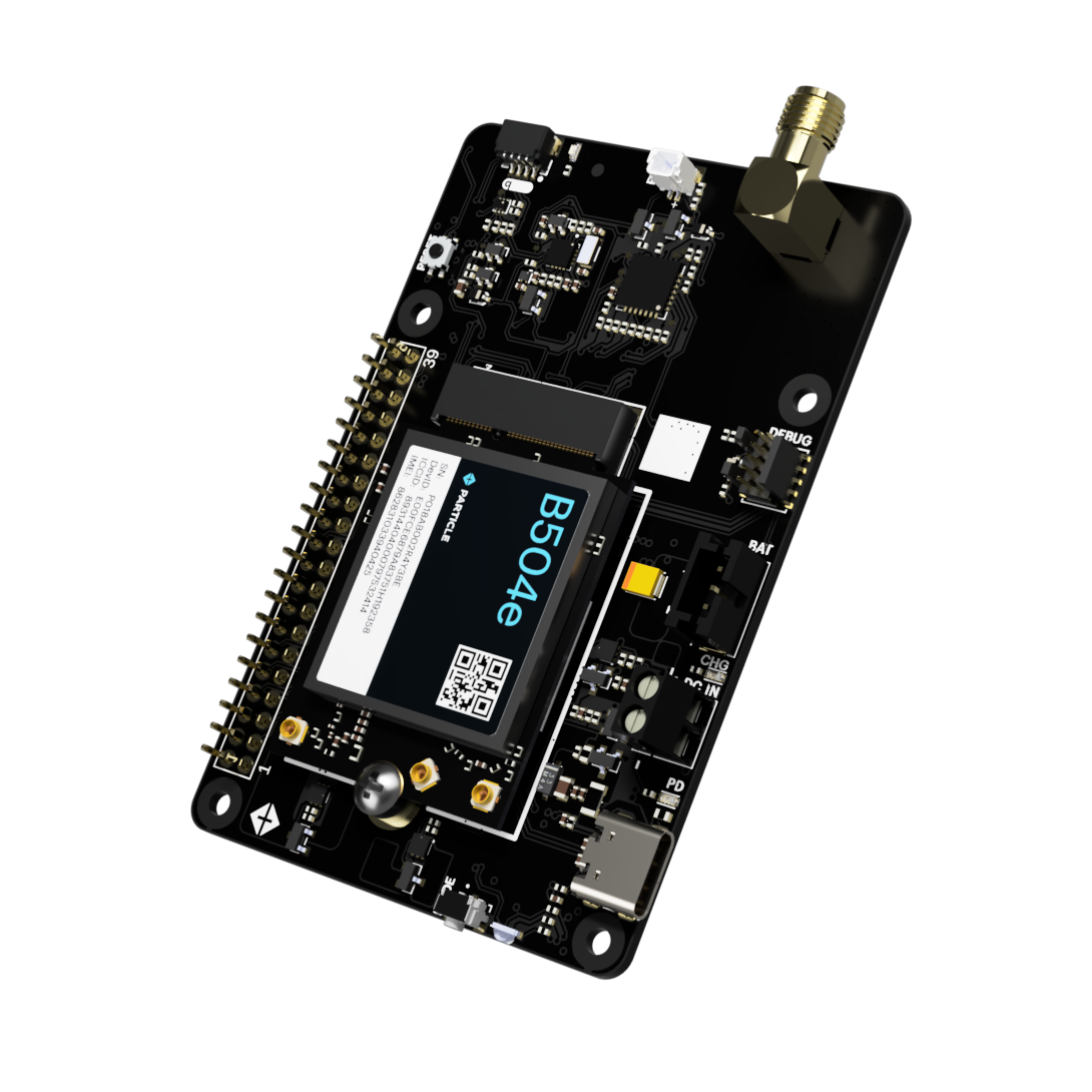
Rendering is of an older version of the M-HAT
Overview
The M-HAT is pass-through HAT (hardware attached on top) for the Raspberry Pi to provide cellular connectivity and power.
It contains the power circuitry similar to the Muon, including the ability to power both the cellular modem and Raspberry Pi using USB-C PD, external DC power, or LiPo battery.
It is intended for use with the B504e (LTE Cat 1 NorAm) and B524 (LTE Cat 1 EMEAA) to provide network connectivity to the Raspberry Pi using tethering.
The M-HAT provides a pass-through Raspberry Pi 40-pin expansion HAT connector to allow use with additional HATs.
If you are using additional Raspberry Pi HATs, you will typically stack them on top of the M-HAT.
If you are using a PoE (Power over Ethernet) HAT, it must go directly against the Raspberry Pi, underneath the M-HAT. This is because PoE has a separate 4-pin connector that directly plugs into to a header next to the Ethernet jack in addition to accessing the 40-pin HAT connector.
Other pass-through HATs could be used below the M-HAT, if they fit and have appropriate stand-offs so the M-HAT remains secure, as well.
Note that the M-SoM does not support tethering and cannot be used to supply a cellular network connection to a Raspberry Pi with the M-HAT.
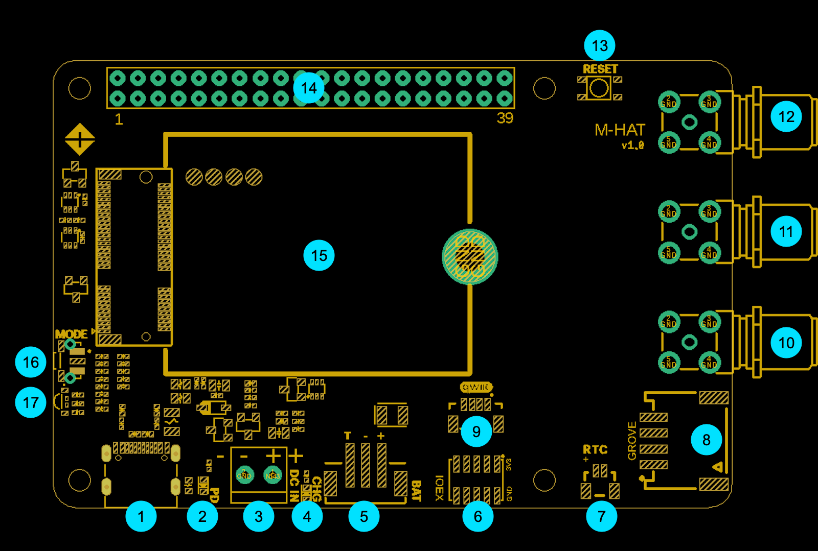
Diagram
| Label | Description | |
|---|---|---|
| 1 | USB-C | |
| 2 | USB-C PD LED | |
| 3 | DC IN | |
| 4 | Charge LED | |
| 5 | LiPo Battery | |
| 6 | I/O Expansion | |
| 7 | RTC Battery | |
| 8 | Grove connector | |
| 9 | Qwiic connector | |
| 10 | SMA connector - GNSS | |
| 11 | SMA connector - BLE | |
| 12 | SMA connector - Cellular | |
| 13 | Particle RESET button | |
| 14 | Raspberry Pi HAT 40-pin connector | |
| 15 | Particle M.2 SoM | |
| 16 | Particle MODE button | |
| 17 | Particle RGB LED |
USB-C (1)
USB-C can be used for powering the M-HAT and the Raspberry Pi.
This USB-C connector also provides USB access to the Particle M.2 SoM for programming over USB or accessing USB serial debug.
It is recommended that you use this USB-C connector instead of the one on the Pi, as the Pi may not provide sufficient power for the cellular modem unless also used with a battery. You should not connect both USB-C cables at the same time.
See also Power, below.
USB-C PD LED (2)
This LED will turn on when USB-C PD (power delivery) has been negotiated with the charger or host.
DC IN (3)
Optional 5V - 12V DC power input (screw terminals).
See also Power, below.
Charge LED (4)
- When lit, the battery is being charged.
- When off, the battery is fully charged, or is not charging because of insufficient power.
- When blinking, there is a battery fault or charging fault.
If you do not have a battery connected, the charge LED may flicker at boot and in DFU mode, and will periodically blink when the device attempts to determine if a battery has been connected.
LiPo Battery (5)
The M-HAT has a 3-pin JST-PH (2mm pitch) battery connector that is the same as the Monitor One, Muon, and Tachyon for connection to a 3.7V LiPo battery pack with an integrated temperature sensor (10K NTC thermistor).
Some other Particle devices have a 3.7V LiPo battery without a temperature sensor using 2-pin JST-PH connector. This battery is not compatible and cannot be used with the Muon.
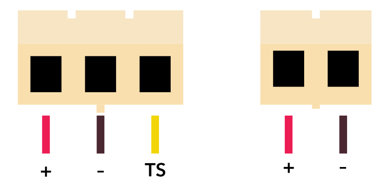
Facing the plug on the battery side
If you wish to use a battery without a 10K NTC temperature sensor, you must cut the normally closed trace jumper indicated, otherwise charging will never enable. Trace jumper JP2 is located to the left of the power module (on the bottom side of the board), with the HAT connector on the side away from you.
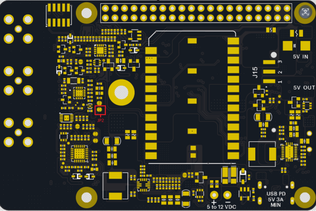
Facing the bottom of the M-HAT
If purchasing a battery from a 3rd-party supplier, verify the polarity as the polarity is not standardized even for batteries using a JST-PH connector.
I/O Expansion (6)
The IOEX connector provides a way to access some of the unused GPIO on the Particle SoM.
It is a 2x5 1.27mm IDC socket that connects using the same ribbon cable that is used for SWD/JTAG debugging on many Particle devices.

| Module Pin | Pin Name | Schematic net | MCU direction | Description |
|---|---|---|---|---|
| 51 | SOM14 | SOM14 | I/O | NC on B-SoM |
| 57 | SOM17 | SOM17 | I/O | NC on B-SoM |
| 58 | D24 | M2_D24 | I/O | On IOEX connector, NC on B-SoM |
| 60 | D25 | M2_D25 | I/O | On IOEX connector, NC on B-SoM |
| 64 | D23 | M2_D23 | I/O | GPIO on IOEX connector |
| 70 | D6 | M2_D6 | I/O | PWM, GPIO on IOEX connector |
RTC Battery (7)
This connector can power the RTC (AB1805) to maintain the real-time clock if all other power sources (USB, DC IN, LiPo) are removed.
This 2-pin 1mm-pitch connector is designed to work with a standard RTC battery module for the Raspberry Pi 5 that typically contains a Lithium coin cell battery.
Grove connector (8)
The Grove connector allows Grove accessories to be added. Pins A1 and A2 are present on the connector. This allows the use of Grove analog and digital sensors.
| Module Pin | Pin Name | Schematic net | MCU direction | Description |
|---|---|---|---|---|
| 33 | A1 | M2_A1/MISO | I/O | Grove A1, Input, Output, ADC, PWM |
| 35 | A2 | M2_A2/SCK | I/O | Grove A2, Input, Output, ADC |
Qwiic connector (9)
Qwiic is a 3.3V I2C standard developed by SparkFun and adopted by other manufacturers. It's also compatible with Adafruit Stemma Qt expansion devices. You can use this to add displays, sensors, etc. and multiple devices can be connected to a single Qwiic port, as accessory boards have two connectors for chaining multiple sensors.
SMA connector - GNSS (10)
The SMA connectors provide an alternative antenna connection. Each is connected to a U.FL pigtail that typically connects to the Particle SoM module such as the B-SoM.
The GNSS antenna is only required if you are using GNSS.
Many off-the-shelf GNSS antennas include a SMA connector, so the built-in adapter can be useful in this case. Since GNSS does not transmit, using an alternative GNSS antenna does not require intentional radiator certification.
SMA connector - BLE (11)
The SMA connectors provide an alternative antenna connection. Each is connected to a U.FL pigtail that typically connects to the Particle SoM module such as the B-SoM.
The BLE antenna is only required if you are using the BLE feature. The B-SoM does not have a built-in BLE chip antenna like the Boron, but BLE is not required for setup.
Often you will attach the Particle 2.4 GHz BLE/Wi-Fi antenna directly to the B-SoM instead of using the SMA connector.
Using an alternative BLE antenna with a SMA connector will require intentional radiator certification.
SMA connector - Cellular (12)
The SMA connectors provide an alternative antenna connection. Each is connected to a U.FL pigtail that typically connects to the Particle SoM module such as the B-SoM.
The cellular antenna is required on the B-SoM. Often you will attach the Particle cellular antenna directly to the B-SoM instead of using the SMA connector.
Using an alternative cellular antenna with a SMA connector will require intentional radiator certification.
Particle RESET button (13)
The RESET button resets the Particle SoM module. It does not reset the Raspberry Pi.
Raspberry Pi HAT 40-pin connector (14)
This is a two-sided pass-through 40-pin Raspberry Pi HAT connector.
It is designed to sit on top of a Raspberry Pi, and allows additional HATs to sit on top of the M-HAT.
The 40-pin Raspberry Pi HAT connector is primarily left for use by the Pi and additional HATs, however the following connections are included between the Particle M.2 SoM and the Pi.

| Pin Name | Schematic net | MCU direction | Description | Pi Pin | Pi Function |
|---|---|---|---|---|---|
| TXD | M2_TXD | O | UART serial TXD, connects to Pi UART0 RXD | GPIO15 | UART0_RX |
| RXD | M2_RXD | I | UART serial RXD, connects to Pi UART0 TXD | GPIO14 | UART0_TX |
| CTS | M2_D3/CTS | I | UART serial CTS, connects to Pi UART0 RTS | GPIO17 | UART0_RTS |
| RTS | M2_D2/RTS | O | UART serial RTS, connects to Pi UART0 CTS | GPIO16 | UART0_CTS |
| CS | WAKE_RPI_CTR | O | Pi power control by GPIO4 | GPIO4 | GPIO4 |
GPIO4 - HAT connector
GPIO4 on the Pi is used for on/off control. While the Pi does not have a true sleep mode like Particle devices, it does use less power in HALT mode and this pin can optionally be used for power control.
The GPIO4 pin has a 10K hardware pull-up resistor to the Pi 3V3.
From the Particle SoM, settings CS pin, also known as D8, to OUTPUT and using digitalWrite(D8, LOW) will set GPIO4 low.
UART serial - HAT connector
The Raspberry Pi UART0 is connected to the Particle M.2 SoM Serial1 UART, with hardware flow control. As is typically the case:
- RXD ↔ TXD
- CTS ↔ RTS
By default, this mapping is isolated. By the SEL pin, see FSA2567, below, you can enable the UART connection, which is needed for tethering.
Particle M.2 SoM (15)
The M-HAT is typically use with a Particle B-SoM B504e or B524 module.
Particle MODE button (16)
The RESET button resets the Particle SoM module. It does not reset the Raspberry Pi.
Particle RGB LED (17)
This is a standard Particle RGB status LED. It is unaffected by the Raspberry Pi.
See the Status LED and device modes page for an explanation of colors and patterns.
Power
Power can be supplied to M-HAT by:
- USB-C
- VIN (5 - 12 VDC, via screw terminals)
- LiPo battery (via 3-pin JST battery connector)
- Expansion card (HAT)
USB-C cable warning
You must use an actual USB-C port or USB-C power adapter to power the M-HAT by USB.
A USB-A to USB-C cable will not power the M-HAT or charge the battery
The reason is that the M-HAT uses USB-C PD to change the USB port voltage to 9V and request enough current to power the M-HAT.
When using a USB-2 or USB-3 port with USB-A to USB-C adapter cable, the USB port voltage cannot be changed and the port will not be able to power the M-HAT.
Also beware of some wall adapters that have a USB-C cable, but do not support USB-C PD. Some of these are advertised as Raspberry Pi power adapters, which only support 5V and cannot be used to power the M-HAT.
See Muon USB Power for more information.
Expansion and peripheral power
The onboard peripherals including QWIIC and Grove connector are powered by the 3V3_AUX power supply.
If you use setup.particle.io to set up your M-HAT, 3V3_AUX will be set up automatically.
If you want to do it manually, the see the section Firmware settings, below, for the sample code and the technical reasons why it is necessary.
HAT power direction jumper
A jumper located on the bottom side of the M-HAT selects the direction of expansion card (HAT) 5V power (label 20, above).
- Connecting
5V_INand center pin: Expansion header powers the M-HAT (typically from a PoE HAT) - Connecting
5V_OUTand center pin: The M-HAT powers expansion card (from USB-C, USB, or LiPo)
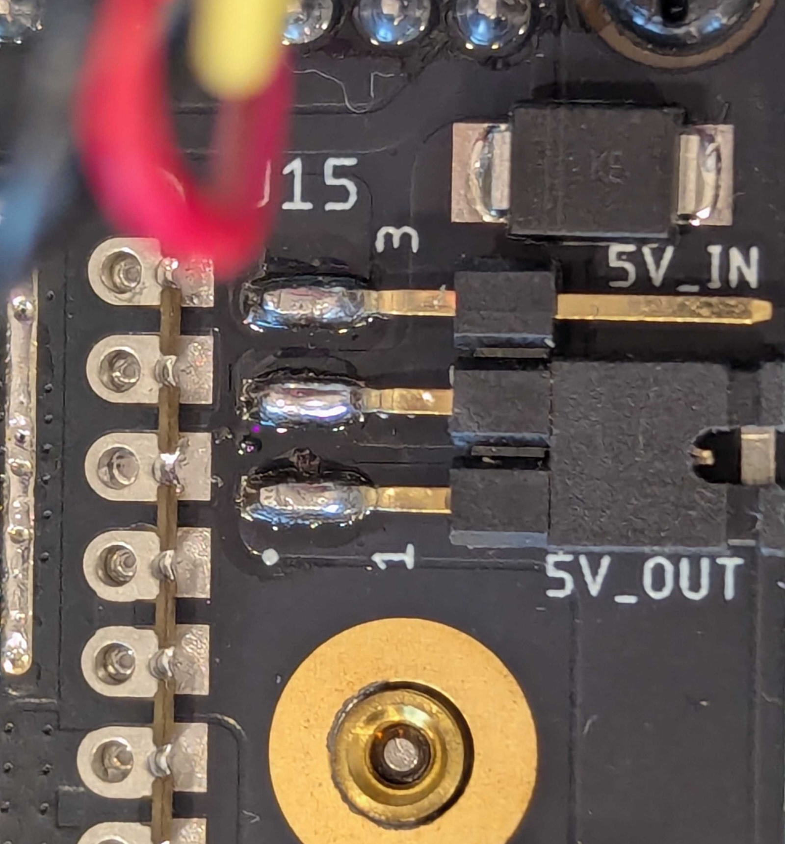
This picture is of the Muon; the appearance of the M-HAT may differ
When the jumper is set to 5V_IN, the M-HAT powers the Raspberry Pi HAT connector 5V pin, which is turn powers the Raspberry Pi itself. When using 5V_IN mode you must not power both the M-HAT USB-C and the Pi USB-C at the same time, as both will attempt to power the HAT 5V pin, which could damage either or both devices.
There are two separate ways 5V on the HAT connector can be generated when powering from M-HAT:
- LiPo boost converter
- DCIN or USB boost-buck converter
The outputs are ORed together using a circuit similar to an ideal diode so none, one, or both can be safely powered at the same time.
Both of these default to on, but can be disabled using GPIO.
| Module Pin | Pin Name | Schematic net | MCU direction | Description |
|---|---|---|---|---|
| 37 | A3 | EN1_CTR | O | LiPo to 5V boost converter (LOW to turn off, default on) |
| 41 | A4 | EN2_CTR | O | DCIN or USB boost-buck converter (HIGH to turn off, default on) |
The EN1_CTR control line connects to the LiPo to 5V boost converter via a 2N7002 N-channel MOSFET to handle the inversion and voltage-level differences.
The EN2_CTR control line connects to the MP28167 boost-buck converter EN pin via a 2N7002 N-channel MOSFET to handle the inversion and voltage-level differences.
Internal peripherals
STUSB4500 - Internal peripherals
The STUSB4500 USB PD controller has three connections, however they are not frequently needed and are hard to access on the B-SoM.
| Module Pin | Pin Name | Schematic net | MCU direction | Description |
|---|---|---|---|---|
| 17 | D21 | PD_RST | O | USB PD controller reset, pin is NFC1 on B-SoM |
| 19 | D20 | PD_ALERT | I | USB PD controller alert, pin is NFC2 on B-SoM |
| 59 | D26 | PD_ATTACH | I | USB PD controller attach interrupt, NC on B-SoM |
If using the B-SoM, it is recommended that you disable NFC in the UICR bytes of the nRF52840. This will allow the MCU to use the NFC pins (NFC1 and NFC2) as GPIO, which will allow you to access the PD_RST and PD_ATTACH pins.
A library and instructions are available for doing so.
PD_RST
This is the PD_RST line to reset the STUSB4500 USB PD controller. You normally will not need to use this.
This is the NFC1 pin on the B-SoM. The NFC pins can be converted from NFC Tag to GPIO, but doing so requires changing the UICR bytes in the nRF52840 configuration flash and rebooting the MCU. After that, the pins will remain as GPIO.
There is a 10K hardware pull-down resistor on this pin. If you set the pin to OUTPUT and HIGH, it will reset the chip.
PD_ALERT
This is the PD_ALERT output from the STUSB4500 USB PD controller. It is not enabled by default.
This is the NFC2 pin on the B-SoM. The NFC pins can be converted from NFC Tag to GPIO, but doing so requires changing the UICR bytes in the nRF52840 configuration flash and rebooting the MCU. After that, the pins will remain as GPIO.
PD_ATTACH
This is the PD_ATTACH output from the STUSB4500 USB PD controller.
This pin is not available on the B-SoM.
FSA2567 - Internal peripherals
This chip isolates the UART pins (RX, TX, CTS, RTS) between the Particle M.2 SoM and the Pi.
If the A0 pin is set HIGH, then the UART is connected:
- RXD ↔ TXD
- CTS ↔ RTS
| Module Pin | Pin Name | Schematic net | MCU direction | Description |
|---|---|---|---|---|
| 23 | A0 | SEL | O | HIGH to enable SoM to Pi UART |
By default, the serial connection is isolated.
To enable the UART connection, you would typically use code like this in your firmware that enabled tethering:
pinMode(A0, OUTPUT);
digitalWrite(A0, HIGH); // enable UART connection
TMP112A - Internal peripherals
This is the temperature sensor on the M-HAT, which is connected by I2C. There is an optional alert output that can be enabled
on the sensor. It is an open-collector output and is connected to D4. If you are using this feature, be sure to set
pinMode(D4, INPUT_PULLUP) so the input does not float. There is no hardware pull-up on tbe M-HAT on this line.
| Module Pin | Pin Name | Schematic net | MCU direction | Description |
|---|---|---|---|---|
| 66 | D4 | TEMP_ALERT | I | Temperature sensor ALERT output |
AB1805 - Internal peripherals
The AB1805 RTC/Watchdog provides additional RTC and hardware watchdog options. It can be powered by:
- USB-C power
- DCIN
- HAT connector (when the jumper is selected to power from HAT)
- LiPo battery
Note that the LiPo battery will power the chip even when the PMIC BATFET is disabled.
The FOUT/IRQ output from the AB1805 is an open-collector output and defaults to Hi-Z in the chip. If you are using this feature, be sure to set
pinMode(D5, INPUT_PULLUP) so the input does not float. There is no hardware pull-up on tbe M-HAT on this line.
| Module Pin | Pin Name | Schematic net | MCU direction | Description |
|---|---|---|---|---|
| 68 | D5 | RTC_INT | I | RTC/Watchdog FOUT/IRQ output |
Additionally, the RTC Battery (7) connector is connected to the VBAT in of the AB1805. This allows the RTC to maintain time when all other sources of power are removed. This feature is optional.
PM-BAT - Internal peripherals
PM-BAT power module includes an open-collector output for interrupts from the bq24195 PMIC
and the MAX17043 fuel gauge. If using this feature, be sure to set pinMode(A7, INPUT_PULLUP) so the input does not float.
| Module Pin | Pin Name | Schematic net | MCU direction | Description |
|---|---|---|---|---|
| 47 | A7 | M2_A7/PMIC_INT | I | PMIC and fuel gauge interrupt output |
| 72 | D7 | D7/AUX_POWER_EN | O | 3V3_AUX power control (HIGH to turn on) |
This output controls the 3V3_AUX power, which also powers:
- Qwiic connector
- Grove connector
Unlike the Muon, AUX_PWR_EN does not control 3.3V and 5V power to the HAT connector.
GPIO - Internal peripherals

| Pin Name | Schematic net | MCU direction | Connected to | Description | M.2 pin |
|---|---|---|---|---|---|
| A0 | SEL | O | FSA2567 | HIGH to enable SoM to Pi UART | 23 |
| A1 | M2_A1/MISO | I/O | Grove A1 | Grove A1, Input, Output, ADC, PWM | 33 |
| A2 | M2_A2/SCK | I/O | Grove A2 | Grove A2, Input, Output, ADC | 35 |
| A3 | EN1_CTR | O | Boost Converter | LiPo to 5V boost converter (LOW to turn off, default on) | 37 |
| A4 | EN2_CTR | O | MP28167 | DCIN or USB boost-buck converter (HIGH to turn off, default on) | 41 |
| A7 | M2_A7/PMIC_INT | I | PM-BAT | PMIC and fuel gauge interrupt output | 47 |
| CS | WAKE_RPI_CTR | O | HAT | Pi power control by GPIO4 | 48 |
| CTS | M2_D3/CTS | I | HAT | UART serial CTS, connects to Pi UART0 RTS | 40 |
| D4 | TEMP_ALERT | I | TMP112A | Temperature sensor ALERT output | 66 |
| D5 | RTC_INT | I | AB1805 | RTC/Watchdog FOUT/IRQ output | 68 |
| D6 | M2_D6 | I/O | IOEX connector | PWM, GPIO on IOEX connector | 70 |
| D7 | D7/AUX_POWER_EN | O | PM-BAT | 3V3_AUX power control (HIGH to turn on) | 72 |
| D20 | PD_ALERT | I | STUSB4500 | USB PD controller alert, pin is NFC2 on B-SoM | 19 |
| D21 | PD_RST | O | STUSB4500 | USB PD controller reset, pin is NFC1 on B-SoM | 17 |
| D22 | 3V3_DETECTION | I | HAT connector | HIGH when Pi is supplying 3V3 to the HAT connector | 62 |
| D23 | M2_D23 | I/O | IOEX connector | GPIO on IOEX connector | 64 |
| D24 | M2_D24 | I/O | IOEX connector | On IOEX connector, NC on B-SoM | 58 |
| D25 | M2_D25 | I/O | IOEX connector | On IOEX connector, NC on B-SoM | 60 |
| D26 | PD_ATTACH | I | STUSB4500 | USB PD controller attach interrupt, NC on B-SoM | 59 |
| MODE | M2/MODE | I | MODE button | MODE button for Particle SoM | 32 |
| RESET | M2/RESET | I | RESET button | RESET button for Particle SoM | 34 |
| RTS | M2_D2/RTS | O | HAT | UART serial RTS, connects to Pi UART0 CTS | 42 |
| RXD | M2_RXD | I | HAT | UART serial RXD, connects to Pi UART0 TXD | 38 |
| SCL | M2_SCL | I/O | Multiple | I2C SCL | 20 |
| SDA | M2_SDA | I/O | Multiple | I2C SDA | 22 |
| SOM14 | SOM14 | I/O | IOEX connector | NC on B-SoM | 51 |
| SOM17 | SOM17 | I/O | IOEX connector | NC on B-SoM | 57 |
| TXD | M2_TXD | O | HAT | UART serial TXD, connects to Pi UART0 RXD | 36 |
I2C
The I2C bus is not shared between the Raspberry Pi and the Particle M.2 SoM. The following internal peripherals are present on the Particle M.2 SoM primary I2C bus (Wire):
| I2C Address | Peripheral |
|---|---|
| 0x28 | STUSB4500 USB-C power controller |
| 0x36 | MAX17043 Fuel Gauge |
| 0x48 | TMP112A temperature sensor |
| 0x69 | AM1805 RTC/Watchdog |
| 0x6B | bq24195 PMIC |
Other
NFC
The M-HAT does not support NFC tag. NFC tag is not supported on the M-SoM, and there is no connector for use with the B-SoM.
SWD/JTAG
The 10-pin SWD/JTAG debugging connector is not populated on the M-HAT.
Additionally, the Particle M.2 SoM SWD pogo pins are not available on the M-HAT, so SWD would only work on M-SoM, not B-SoM, even if populated.
Note that the 2x5 connector on the top of the M-HAT is the IOEX connector, not the debug connector, even though the debug cable does fit in the connector.
Firmware settings
Devices using the Particle Power Module include a 3V3_AUX power output
that can be controlled by a GPIO. On the M-HAT, it controls the Qwiic and Grove connectors.
On the M.2 SoM breakout board, this powers the Feather connector. On the Muon,
it powers the Ethernet port, LoRaWAN module, 40-pin expansion HAT connector, and QWIIC connector.
The main reason for this is that until the PMIC is configured, the input current with no battery
connected is limited to 100 mA. This is insufficient for the M-SoM to boot when
using a peripheral that requires a lot of current, like the WIZnet W5500 Ethernet module. The
system power manager prevents turning on 3V3_AUX until after the PMIC is configured
and the PMIC has negotiated a higher current from the USB host (if powered by USB).
This setting is persistent and only needs to be set once. In fact, the PMIC initialization
normally occurs before user firmware is run. This is also necessary because if you are using Ethernet
and enter safe mode (breathing magenta), it's necessary to enable 3V3_AUX so if you are using
Ethernet, you can still get OTA updates while in safe mode.
After changing the auxiliary power configuration you must reset the device.
Tethering code - Firmware settings
The following code can be added to your application to enable the UART interface connection and enable tethering so the Raspberry Pi can use the B-SoM cellular connection.
- For general information, see Tethering.
- For information about the
Tetherclass, see the Device OS API reference.
Note that the M-SoM does not support tethering and cannot be used to supply a cellular network connection to a Raspberry Pi with the M-HAT.
One-time configuration - Firmware settings
The following code can be used to enable 3V3_AUX power on the M-HAT. This only needs to be done once and the device must be reset after configuration for the changes to take effect. It requires Device OS 5.9.0 or later.
// Enable 3V3_AUX
SystemPowerConfiguration powerConfig = System.getPowerConfiguration();
powerConfig.auxiliaryPowerControlPin(D7).interruptPin(A7);
System.setPowerConfiguration(powerConfig);
Manual configuration - Firmware settings
If you wish to manage the 3V3_AUX power manually from your firmware,
you can set the auxiliaryPowerControlPin to PIN_INVALID and reset the device. It will then no longer
turn on at boot.
// Manual management of 3V3_AUX
SystemPowerConfiguration powerConfig = System.getPowerConfiguration();
powerConfig.auxiliaryPowerControlPin(PIN_INVALID).interruptPin(A7);
System.setPowerConfiguration(powerConfig);
To control 3V3_AUX manually from your firmware, use pinMode(D7, OUTPUT) in setup(). Use
digitalWrite(D7, 1) to turn 3V3_AUX on and digitalWrite(D7, 0) to turn it off.
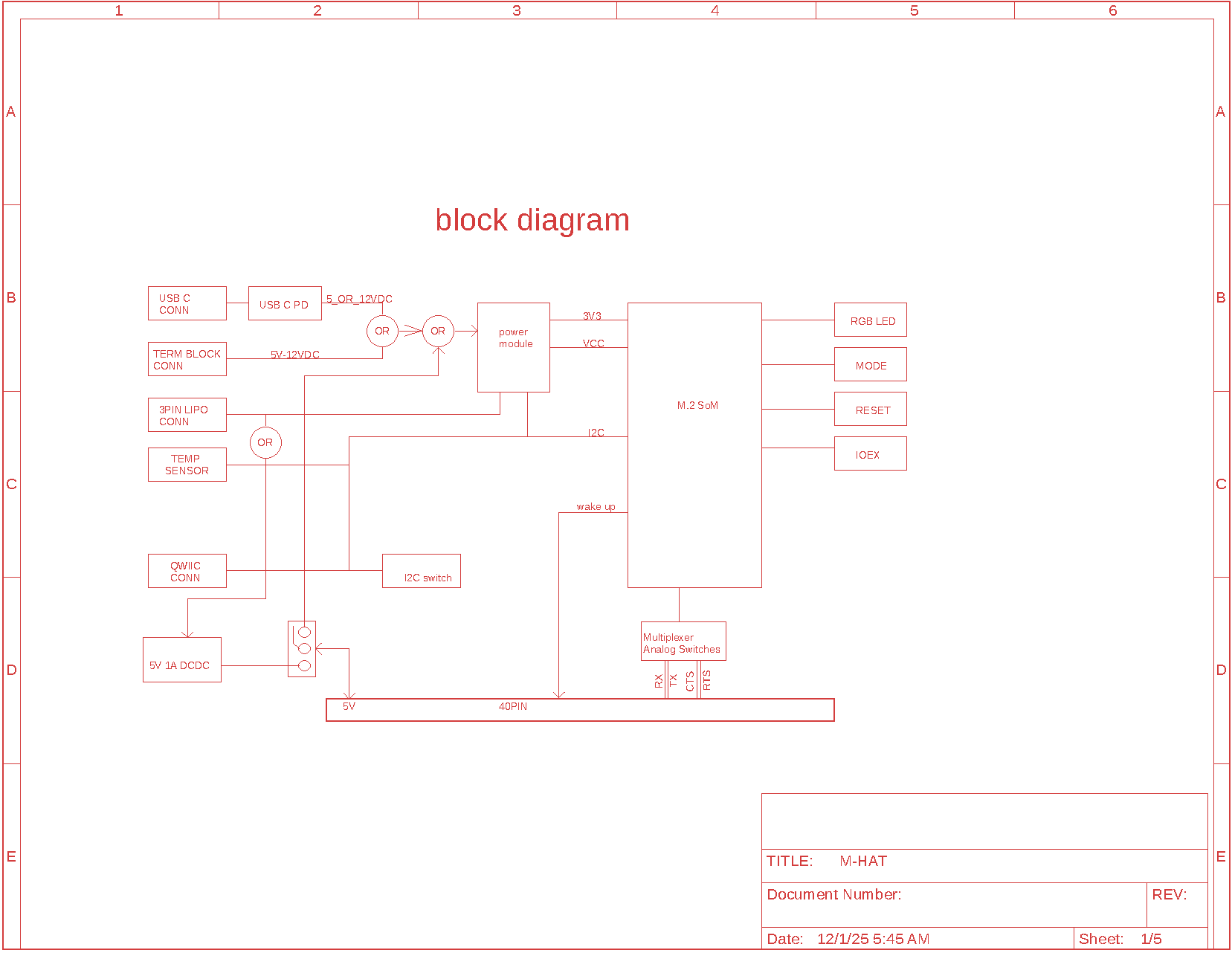
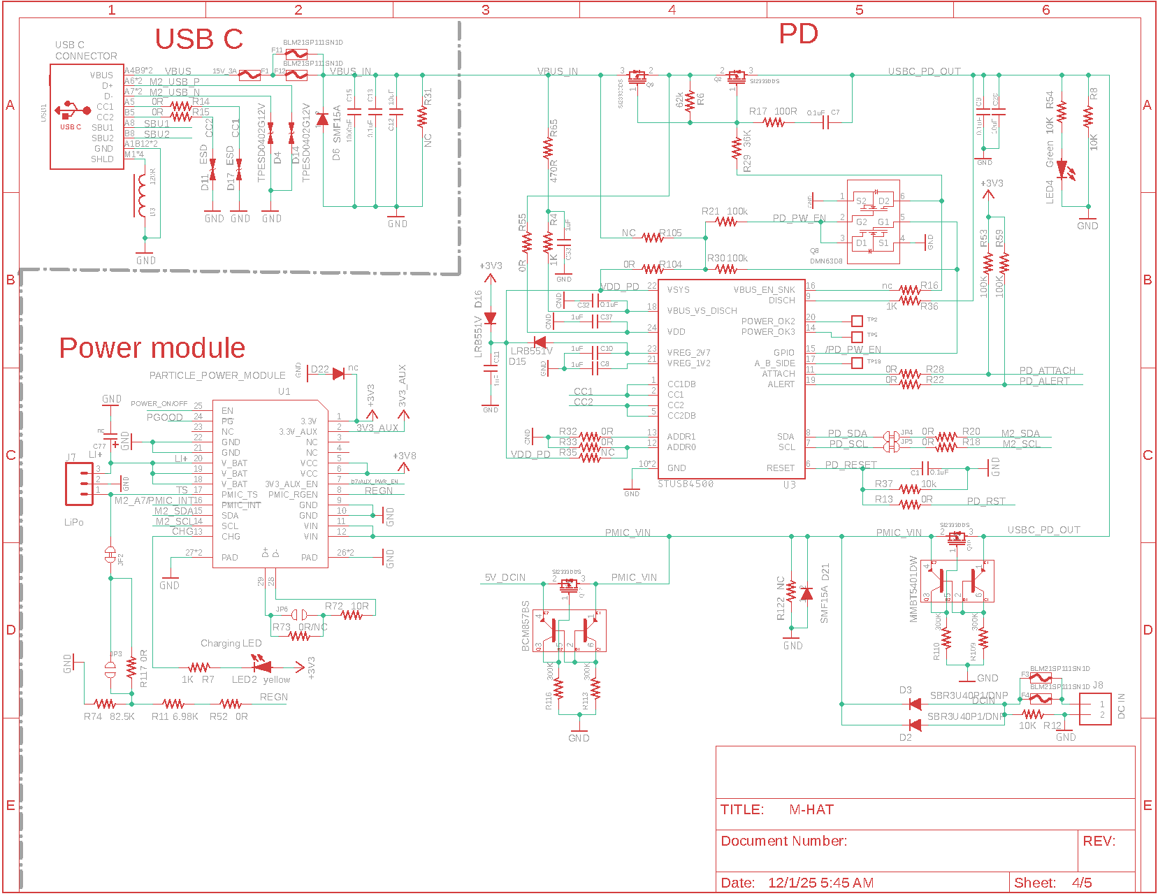
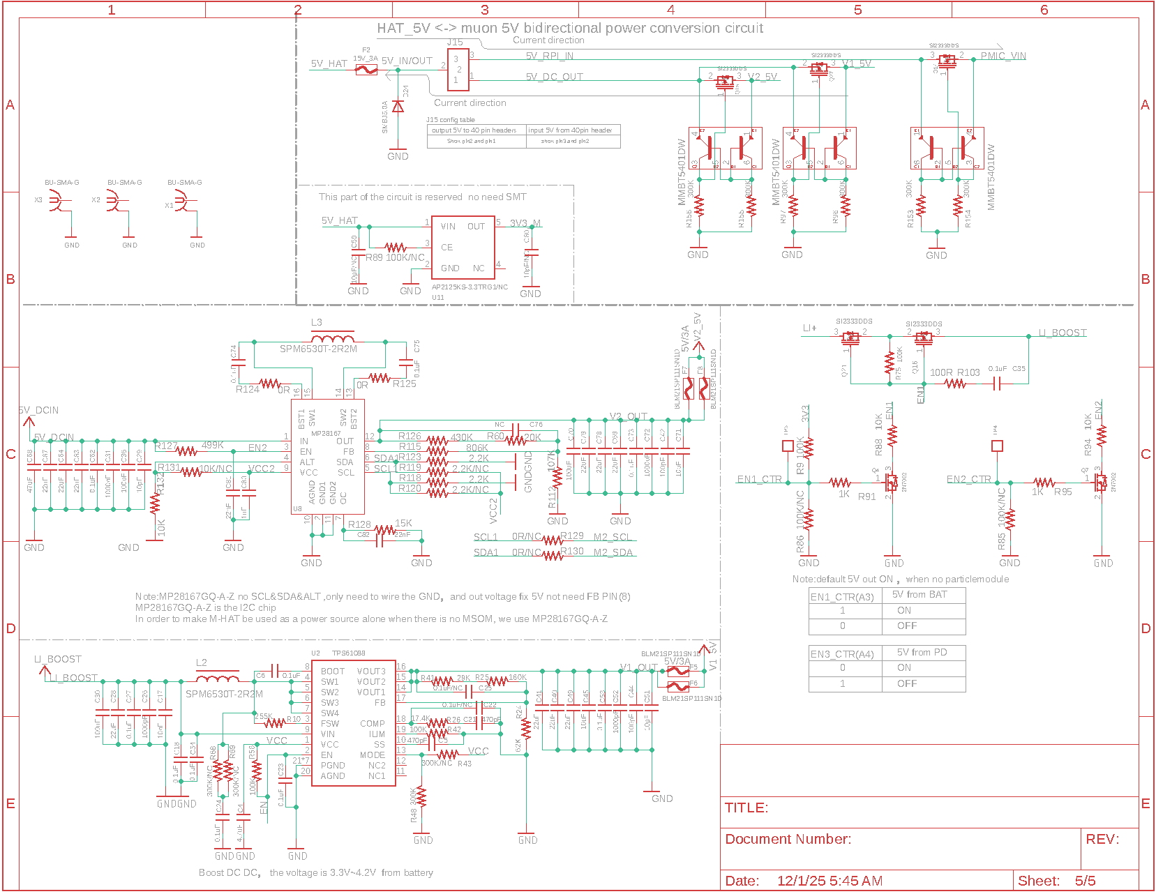
Schematics
Schematics page 1
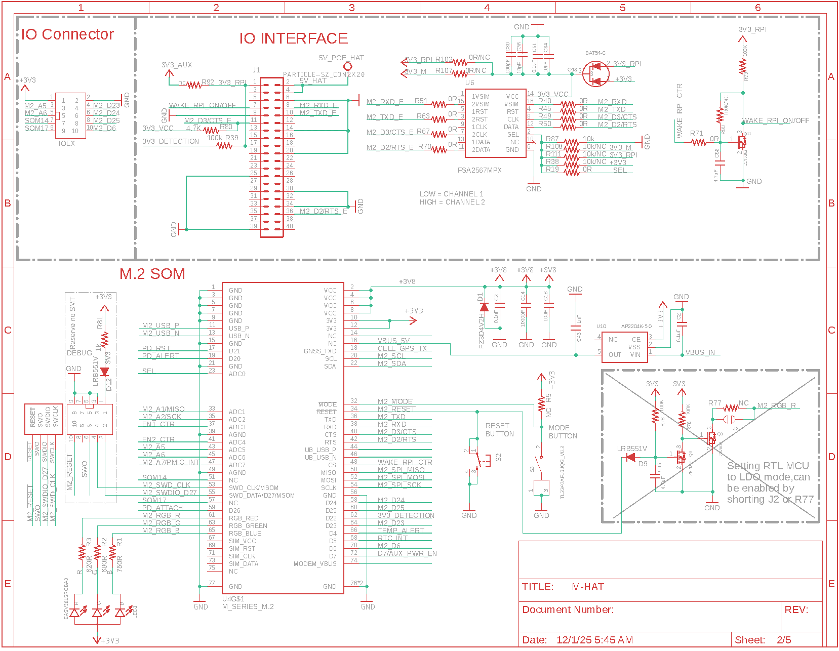
Schematics page 2
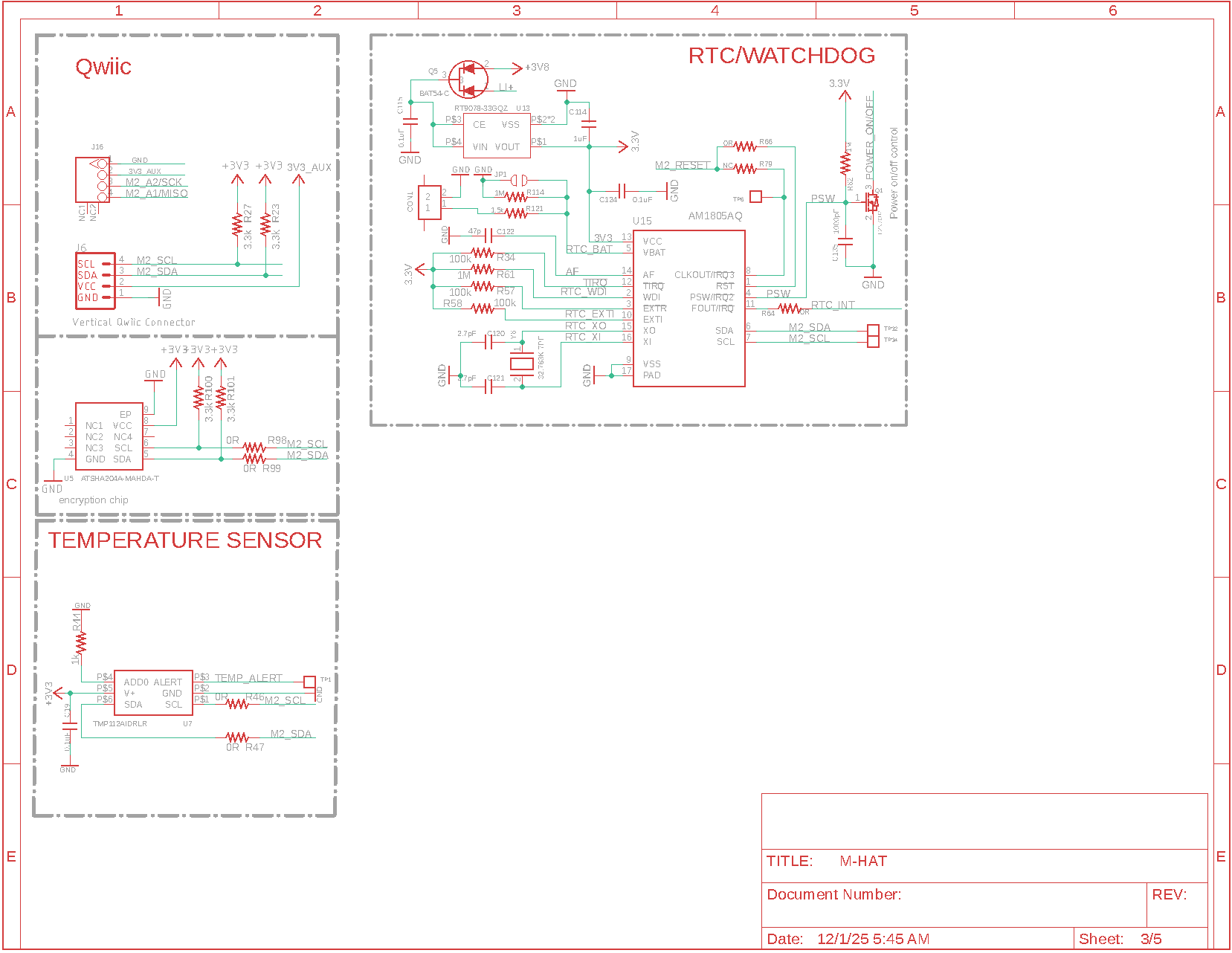
Schematics page 3
Schematics page 4
Schematics page 5
Certification
The cellular (intentional radiator) certification depends on the cellular module you have selected.
If you are building a product with the M-HAT and are using the Particle certified cellular antenna you may not need to complete intentional radiator testing.
You will likely need to perform unintentional radiator testing with your compete module, however. Fortunately this is generally the least expensive and least complicated test.
Cellular carriers
The cellular carriers are dependent on the Particle M.2 SoM you have selected for your M-HAT. See the carrier list for more information.
Ordering information
| SKU | Description | Region | Lifecycle |
|---|---|---|---|
| MHAT | M-HAT | Global | In development |
| MHAT504e | M-HAT with LTE CAT1 for North America | NORAM | In development |
| MHAT524e | M-HAT with LTE CAT1 for Rest of World | EMEAA | In development |
- EMEAA: Selected countries in Europe, Middle East, Africa, and Asia, including Australia and New Zealand. See the cellular carrier list for more information.
Revision history
| Revision | Date | Author | Comments |
|---|---|---|---|
| pre | 2024-04-21 | RK | Initial version |
| 2026-03-19 | RK | Minor updates |