
M8 Accessories(004)
M8 Pinouts
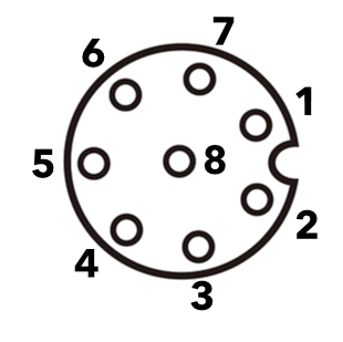
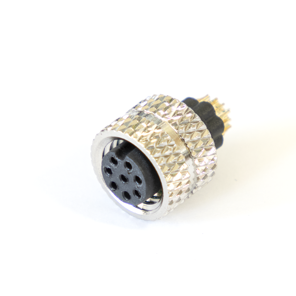
M8 Connector on cable
Facing sockets on connector end of cable
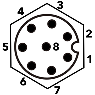
M8 Connector on Tracker One
Facing pins on the panel connector from the outside of the case
The 8-pin connector has these signals:
| M8 Pin | Function | Function | Function | I/O | Color |
|---|---|---|---|---|---|
| 1 | CAN_P | IO2 | Yellow | ||
| 2 | VIN3 | I | Red | ||
| 3 | Analog A3 | GPIO D3 | IO1 | White | |
| 4 | Serial1 RX | Wire3 SDA | GPIO D9 | IO1 | Green |
| 5 | Serial1 TX | Wire3 SCL | GPIO D8 | IO1 | Brown |
| 6 | CAN_5V4 | CAN_PWR | O | Orange | |
| 7 | CAN_N | IO2 | Blue | ||
| 8 | GND | Black |
1MCU GPIO is limited to 3.3V maximum.
2CAN Bus specifications can be found in the Tracker SoM datasheet.
36.0 to 30 VDC at 2A when using the M8 connector.
45V, 370 mA maximum. Controlled by the CAN_PWR GPIO.
You typically connect the cable to your custom external interface device by routing the cable through a cable gland in your enclosure and to your custom board and:
- Terminate with pins in a PHR-8 to mate with a B8B-PH on your expansion board
- Terminate with screw terminals on your board
- Terminate by soldering the wires to your board
For more information on expanding your Tracker One using the M8 connector, see the Tracker One Expansion Tutorials.
You must enable CAN_5V in order to use GPIO on M8 pins 3, 4, and 5 (A3, D9/RX/SDA, D8/TX/SCL) on the Tracker One. If CAN_5V is not powered, these pins are isolated from the MCU starting with version 1.1 of the Tracker One/Tracker Carrier Board (September 2020 and later). This is necessary to prevent an issue with shipping mode, see technical advisory note TAN002.
M8 Cables
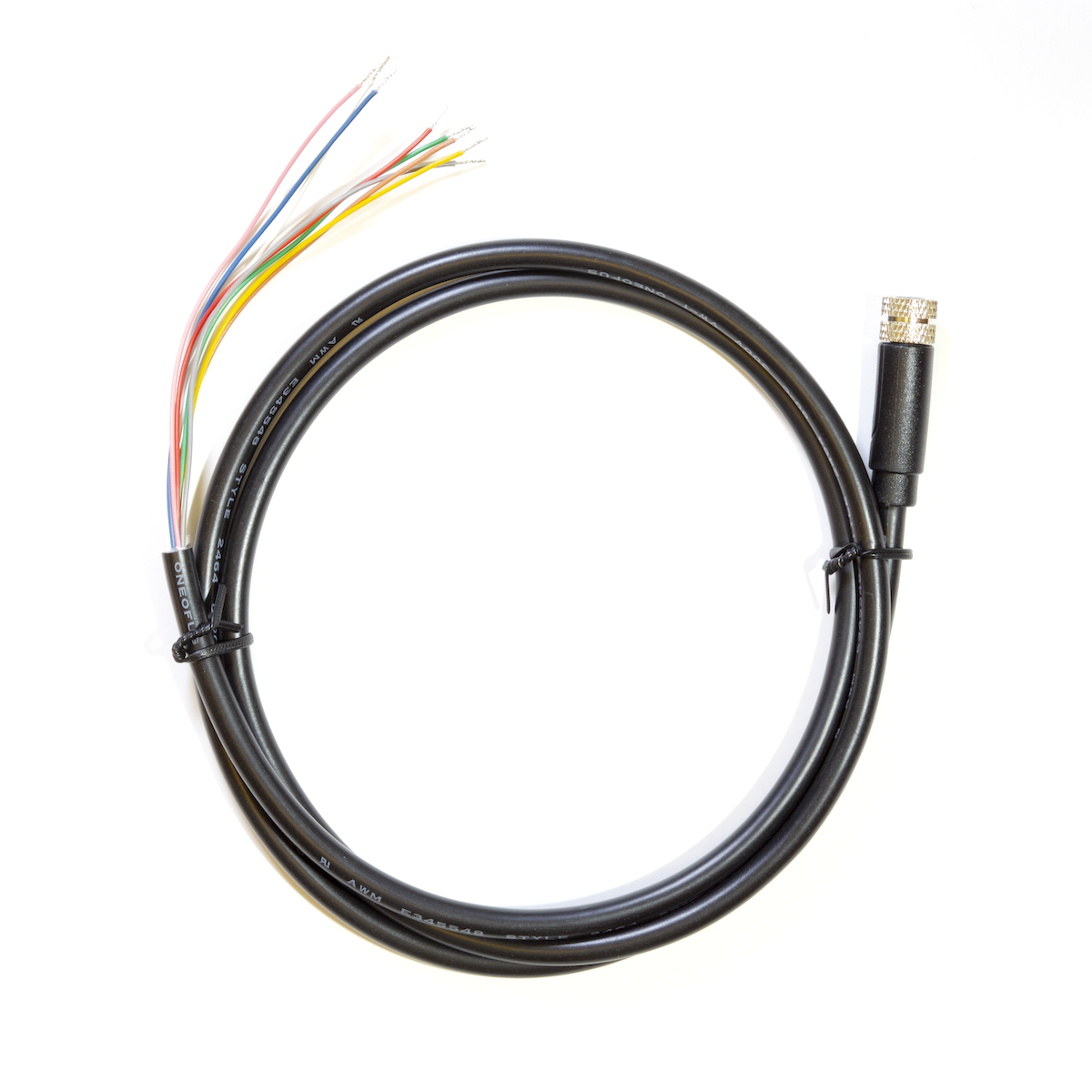
The M8 cables provide a convenient way to connect external devices to the Tracker One while preserving the IP67 waterproof rating and not having to disassemble the Tracker One.
Wire gauge - M8 cables
| M8 Pin | Function | Color | Wire Gauge |
|---|---|---|---|
| 1 | CAN_P | Yellow | 26 AWG |
| 2 | VIN | Red | 24 AWG |
| 3 | A3 | White | 26 AWG |
| 4 | RX_SDA_D9 | Green | 26 AWG |
| 5 | TX_SCL_D8 | Brown | 26 AWG |
| 6 | CAN_5V | Orange | 26 AWG |
| 7 | CAN_N | Blue | 26 AWG |
| 8 | GND | Black | 24 AWG |
Dimensions - M8 cables
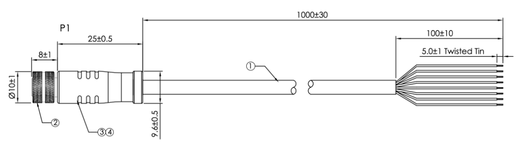
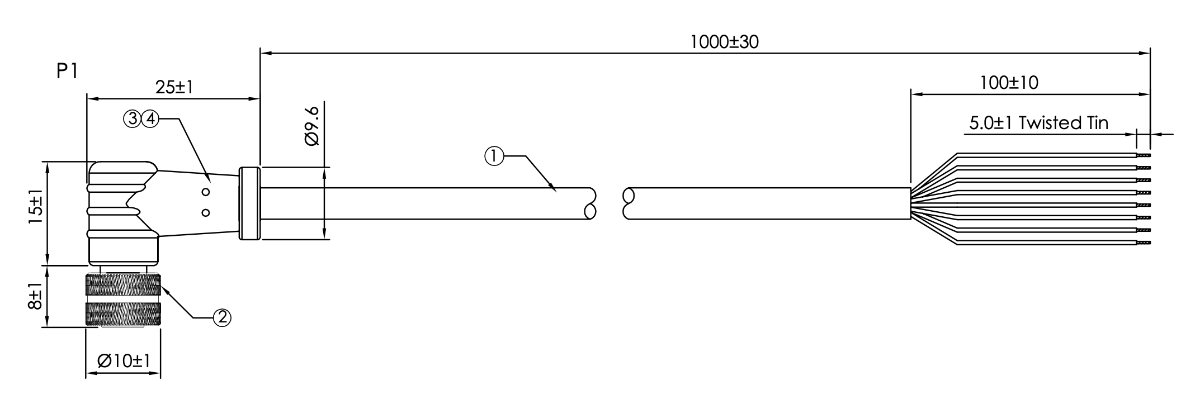
| Parameter | Value |
|---|---|
| Length | 1 meter ±3 cm |
| Outer jacket stripped | 10 cm ±1 cm |
| Inner wires stripped and tinned | 5 mm ±1 mm |
| Outer Diameter | 5.0 mm |
| Approvals | UL2464, RoHS |
Orientation - M8 cables
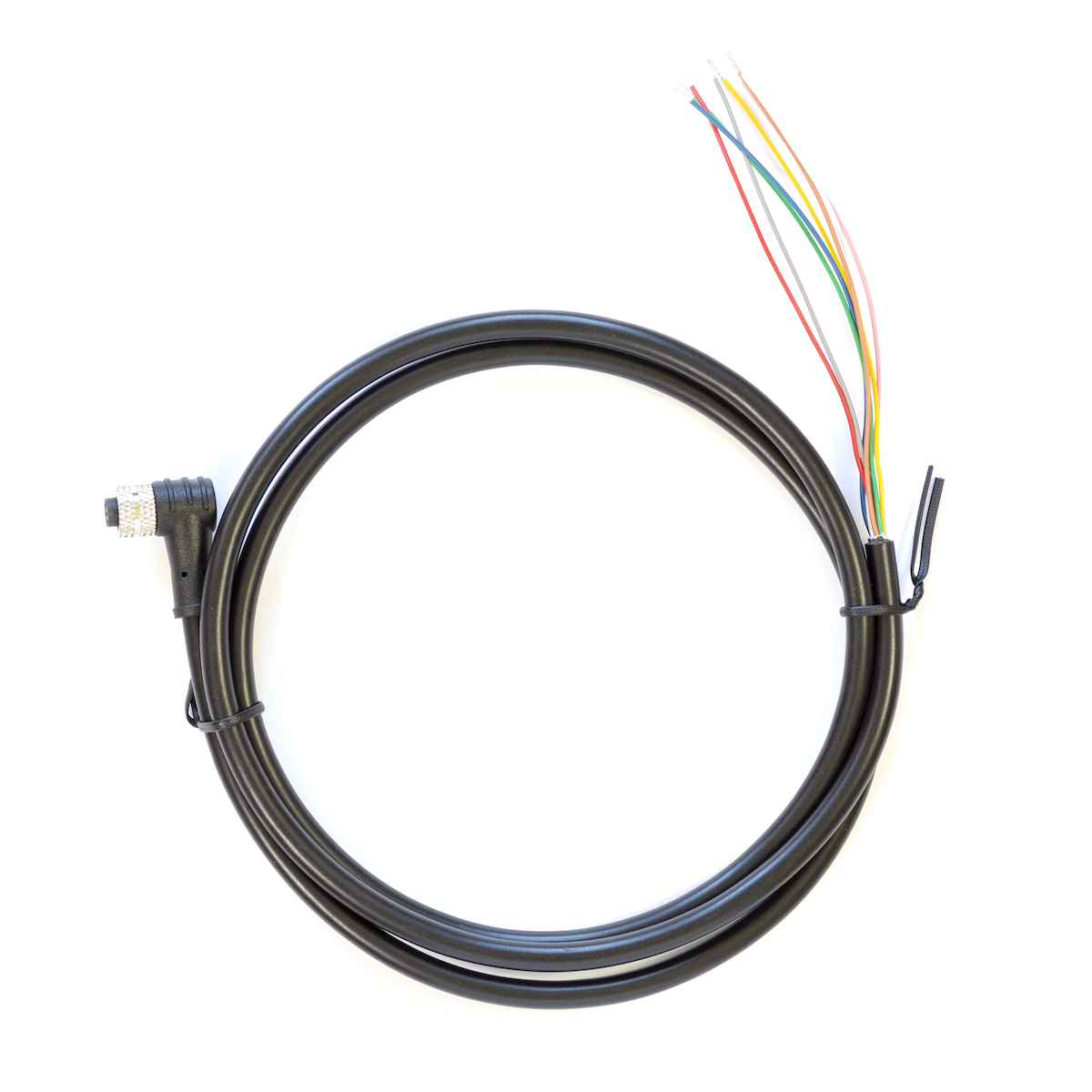
The key on the M8 panel connector is at 3 o'clock (right side, nearest to the USB connector), when facing the connectors, as in the diagram above. When using the right-angle M8 cable, the cable will face away from the USB connector.
![]()
SKUs - M8 Cables
| SKU | Description |
|---|---|
| M8CABEA | Tracker One M8 Accessory Cable (Straight), (x1) |
| M8CABTY | Tracker One M8 Accessory Cable (Straight), (x40) |
| M8CABRAEA | Tracker One M8 Accessory Cable (Right Angle), (x1) |
| M8CABRATY | Tracker One M8 Accessory Cable (Right Angle), (x40) |
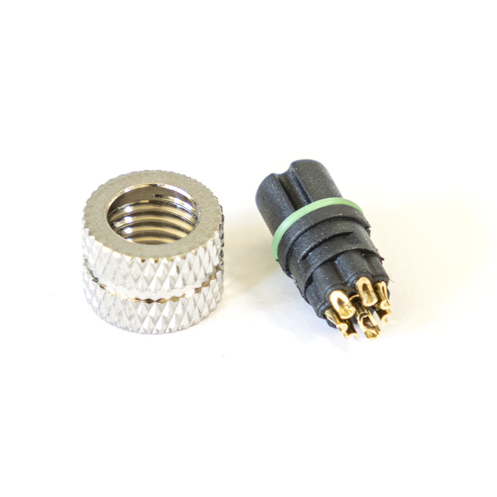
M8 Connector
The M8CONNEA and M8CONNTY are a connector similar to the M8 connector on the straight ONEM8CAB. It's intended for building your own M8 cable assembly and is the female side of the connector that mates with the Tracker One M8 connector. It is a bare connector and does not include a shroud. It is intended that your cable manufacturer will add an overmold to seal your cable to the connector.
SKUs - M8 Connector
| SKU | Description |
|---|---|
| M8CONNEA | Tracker One M8 Connector (Straight), (x1) |
| M8CONNTY | Tracker One M8 Connector (Straight), (x40) |
This connector has the same pinouts as the cable above, but without the cable, so you can substitute your own cable of the desired length.
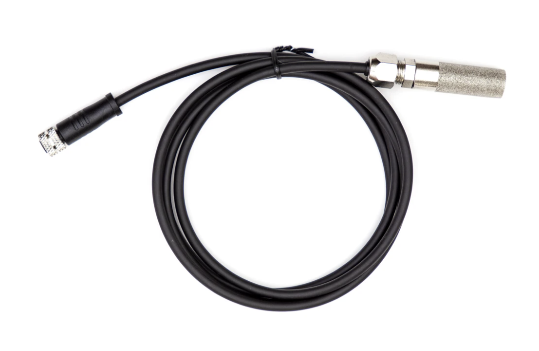
Other sensors
M8 Temperature/Humidity
Revision history
| Revision | Date | Author | Comments |
|---|---|---|---|
| 001 | 2020 Sep 15 | RK | First release |
| 002 | 2021 Feb 03 | RK | Change M8 CAN output current to 370 mA |
| 003 | 2021 Feb 10 | RK | Update picture of ONEM8CONN |
| 004 | 2021 Feb 17 | RK | Add note about Tracker One M8 GPIO requiring CAN_5V |