Tracker One expansion
Designing on Particle is a series of video tutorials that center best practices across the Particle platform. This video covers the Tracker basics including Tracker Edge, adding custom data to location publishes, and adding new settings panels for your own custom settings to the Particle console using a configuration schema.
Tracker One M8 connector
The Tracker One can be expanded without opening the case by using the M8 connector.
Particle gateway devices, including the Tracker One, and it's larger relative, the Monitor One, are off-the-shelf designs that include an enclosed cellular module and a connector to attach additional sensors and other devices by protocols such as CAN bus, serial, or I2C interfaces.
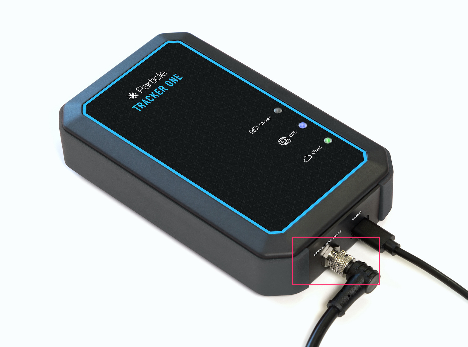
This connector can be used while maintaining the IP67 rating.
The 8-pin connector has these signals:
| M8 Pin | Function | Function | Function | I/O | Color |
|---|---|---|---|---|---|
| 1 | CAN_P | IO2 | Yellow | ||
| 2 | VIN3 | I | Red | ||
| 3 | Analog A3 | GPIO D3 | IO1 | White | |
| 4 | Serial1 RX | Wire3 SDA | GPIO D9 | IO1 | Green |
| 5 | Serial1 TX | Wire3 SCL | GPIO D8 | IO1 | Brown |
| 6 | CAN_5V4 | CAN_PWR | O | Orange | |
| 7 | CAN_N | IO2 | Blue | ||
| 8 | GND | Black |
1MCU GPIO is limited to 3.3V maximum.
2CAN Bus specifications can be found in the Tracker SoM datasheet. CAN Bus termination is provided on the carrier board.
36.0 to 30 VDC at 2A when using the M8 connector. 6.0 - 90 VDC at 2A when connecting directly to the board.
45V, 370 mA maximum. Controlled by the CAN_PWR GPIO.
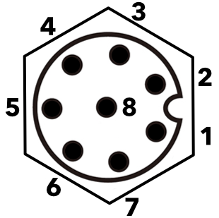
View as looking into the M8 connector on the outside of the enclosure.
Interface details
Power (in)
While the picture above includes both USB-C and M8 cables, it's also possible to power the Tracker One from the M8 connector. In this case, supply 6.0 to 30 VDC at 2 A.
Power (out)
There is an optional 5V 370 mA power output (CAN 5V) that is controlled by the CAN_PWR GPIO. It is available in all power modes (battery, USB, and VIN); there is an on-board boost converter to produce 5V from the 3.7V LiPo battery.
If you are building an expansion device that is battery or USB powered, you can use CAN 5V to power your expansion device, eliminating the need to add a separate power supply. Note that this is limited to 370 mA at 5V and the Tracker SoM GPIO are limited to 3.3V, so you may need to add a 3.3V regulator on your expansion board to convert CAN 5V to 3.3V.
CAN
A CAN BUS interface is provided. The two differential CAN bus signals are provided (CAN+ and CAN-).
Multi-function pins
There are three multi-function pins:
| M8 Pin | Function | Function | Function |
|---|---|---|---|
| 3 | Analog A3 | GPIO D3 | |
| 4 | Serial1 RX | Wire3 SDA | GPIO D9 |
| 5 | Serial1 TX | Wire3 SCL | GPIO D8 |
You must enable CAN_5V in order to use GPIO on M8 pins 3, 4, and 5 (A3, D9/RX/SDA, D8/TX/SCL) on the Tracker One. If CAN_5V is not powered, these pins are isolated from the MCU starting with version 1.1 of the Tracker One/Tracker Carrier Board (September 2020 and later). This is necessary to prevent an issue with shipping mode, see technical advisory note TAN002.
For example: If you are using Serial1, you cannot use Wire3 (I2C) and can only use one other GPIO (D3).
If you are using Wire3 (I2C), you can't use Serial1 or D8 or D9.
If you aren't using Wire3 or Serial1, you can use all three pins as GPIO, or use D8 and D9 as GPIO and A3 as analog input (ADC).
If you are in need of more ports, the best solution is to use the multi-function pins as I2C, and include an I2C expander on your expansion board. Some things you can add using I2C:
- More GPIO using a MCP23008 (8-port) or MCP23017 (16-port)
- ADCs (like the MCP3021 single port)
- PWM (pulse-width modulation output) using a PCA9685 (16-channel) for servos or LEDs
- Temperature, humidity, and pressure sensors
- Displays (LED, OLED, LCD, etc.)
- Serial UART (SC16IS740)
- FRAM non-volatile data storage
Note that Serial, I2C, GPIO, and ADC on the Tracker SoM can only be used at 3.3V maximum. The pins are not 5V tolerant!
Connecting your expansion device
The M8 (8mm) 8-pin connector is standard, however it's not common. Some other connectors like M12 are more common, however, the 12mm connector would have required a taller enclosure to fit the larger connector. To simplify designs, Particle will provide a M8 female-to-wires cable, similar to this.
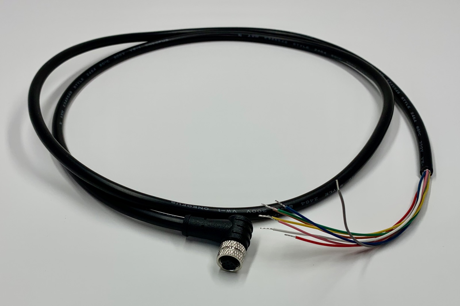
Additional information can be found in the M8 Accessories Datasheet.
The common use case will be to include a cable gland in your expansion enclosure, pass the wires through the gland, and terminate them on your custom expansion board.
You'd typically connect those wires to your custom expansion board using one of several methods:
- Terminate with pins in a PHR-8 to mate with a B8B-PH on your expansion board
- Terminate with screw terminals on your board
- Terminate by soldering the wires to your board
The following cables will be available:
| SKU | Description |
|---|---|
| M8CABEA | Tracker One M8 Accessory Cable (Straight), (x1) |
| M8CABTY | Tracker One M8 Accessory Cable (Straight), (x40) |
| M8CABRAEA | Tracker One M8 Accessory Cable (Right Angle) |
| M8CABRATY | Tracker One M8 Accessory Cable (Right Angle), (x40) |
| M8CONNEA | Tracker One M8 Connector (Straight) |
| M8CONNTY | Tracker One M8 Connector (Straight), (x40) |
The color code is as follows:
| M8 Pin | Function | Color |
|---|---|---|
| 1 | CAN_P | Yellow |
| 2 | VIN | Red |
| 3 | A3 | White |
| 4 | RX_SDA_D9 | Green |
| 5 | TX_SCL_D8 | Brown |
| 6 | CAN_5V | Orange |
| 7 | CAN_N | Blue |
| 8 | GND | Black |
Note that CAN bus is differential and consists of two lines:
- CAN_P (positive), CANH (high), or CAN+
- CAN_N (negative), CANL (low), or CAN-
As the signals are differential you don't need to connect GND for CAN bus, but you do still need to connect it for Serial, I2C, or GPIO.
With the Tracker One carrier board
Inside the Tracker One is the Carrier Board. It can be purchased separately in case you want to use the Tracker One features in your own enclosure. The design for the Tracker One enclosure is open-source and can be modified to fit your needs. The Carrier Board has a B8B-PH 8-pin connector on the board, and a short cable that attaches to the M8 8-pin IP67 connector mounted on the side of the enclosure.
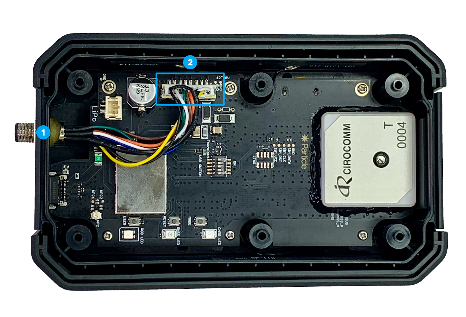
| Label | Description |
|---|---|
| 1 | M8 Connector |
| 2 | B8B-PH Connector |
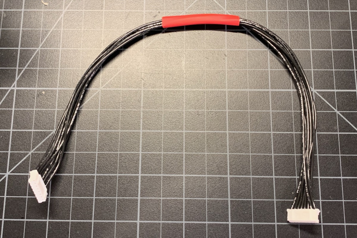
When expanding on the Tracker One Carrier Board, you may prefer to connect your expansion device to the B8B-PH connector on the board directly, especially if you are putting your expansion board an the enclosure with your Tracker One Carrier Board using a PHR-8 to PHR-8 cable. This can be easily assembled or purchased and is inexpensive.
Application notes
| App Note | 3.3V | Qwiic | GPIO | 5V I2C | DAC | ADC | Boost | Description |
|---|---|---|---|---|---|---|---|---|
| AN012 | ✓ | ✓ | ✓ | 1-Wire (DS18B20) | ||||
| AN013 | ✓ | ✓ | ✓ | GPIO (3.3v or 5V) | ||||
| AN015 | ✓ | ✓ | Breakout Board | |||||
| AN016 | ✓ | ✓ | ✓ | Keypad and LEDs | ||||
| AN018 | ✓ | ✓ | ✓ | ✓ | Tank Level Sensor | |||
| AN020 | ✓ | 4-20mA single | ||||||
| AN021) | ✓ | ✓ | ✓ | 4-20mA quad | ||||
| AN022 | ✓ | ✓ | SHT3x Temperature/Humidity |
M8 Breakout board
The AN015 Tracker Breakout application note shows how to build a simple breakout board to help prototype using the Tracker One M8 connector.
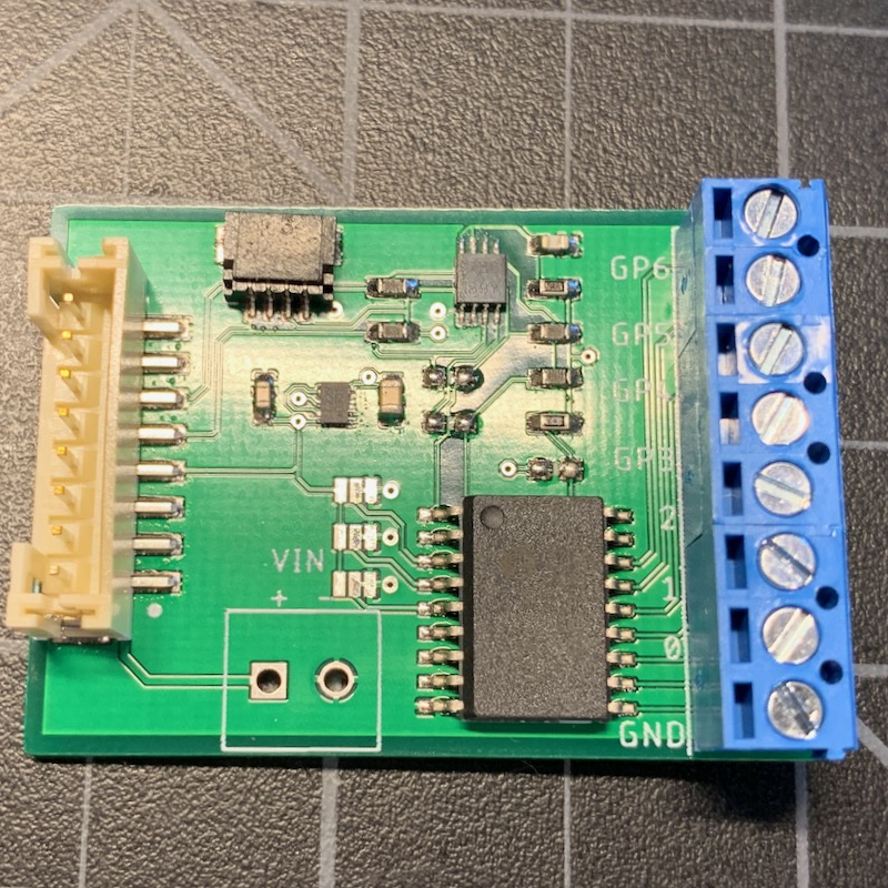
Adding GPIO using the M8
The AN013 Tracker GPIO shows:
- Expanding the Tracker One using the M8 connector.
- Interfacing with 5V I2C devices (optional).
- Adding a MCP23008 to add 8 GPIO. Can be configured as 3.3V or 5V GPIO at board assembly time.
The Tracker One M8 connector only has three available pins for GPIO, and two of them are shared with serial and I2C. By using an external MCP23008 I2C GPIO interface, you can add many more GPIO pins.
The nRF52840 MCU GPIO is 3.3V only, and is not 5V tolerant. You can use the techniques in this application note to interface with 5V GPIO with true 5V logic levels.
The MCP23008 allows the pins to be configured for input, input pull-up, or output. In input mode the pins are high-impedance (Hi-Z) so you can use that to implement open-collector style output as well.
1-Wire (DS18B20) and using 5V I2C
The AN012 Tracker 1-Wire shows:
- Expanding the Tracker One using the M8 connector
- Interfacing with 5V I2C devices
- Using the DS2482-100 I2C to 1-Wire interface to efficiently add 1-Wire devices
- Using the DS18B20 temperature sensors
- Adding custom data to your location publishes
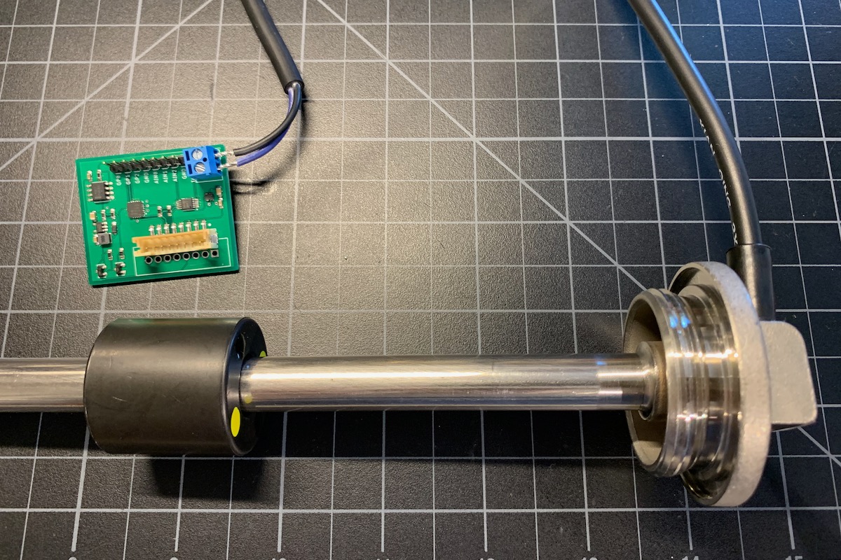
Tank level sensor
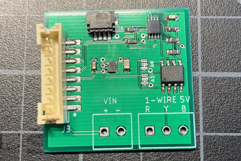
The AN018 Tracker Tank Level Sensor shows:
- Adding additional GPIO (adds 3 ports of 3.3V GPIO using a MCP23008)
- Adding additional ADC (adds 3 ADC inputs, 3.3V using an ADS1015 12-bit ADC)
- Support for a tank level sensor (240-33 ohm, common in the US)
- 12V boost converter, for powering low-power 12V sensors (needed for tank sensor)
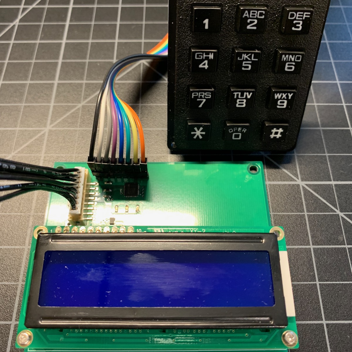
Keypad and LCD
The AN016 Tracker Keypad LCD shows:
- Using a MAX7360 to read matrix keypads and drive LEDs
- Using a character LCD display with an I2C interface
- Interfacing to 5V I2C devices
- Using an I2C DAC (digital to analog converter), used to handle the contrast for the LCD
- Implementing cloud-configurable settings (contrast)
- Adding data to location events (keypad digits)
- Showing GNSS lock and cloud connection status with custom LEDs
You probably won't want to build one of these as-is, but you may want to use some of the techniques in your own designs.
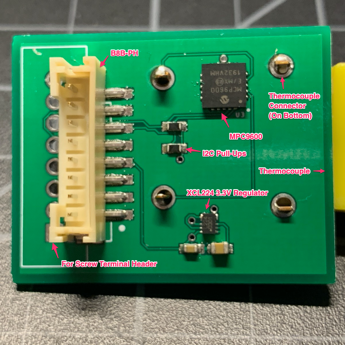
Thermocouple (prototype to making your own board)
The AN019 Tracker Prototype to Board application note demonstrates how start prototyping with off-the-shelf I2C sensors and the Tracker SoM Evaluation Board and migrate to using a custom board for the Tracker One M8 Connector. While this specific example is for a thermocouple sensor, the techniques can be used with any sensor.
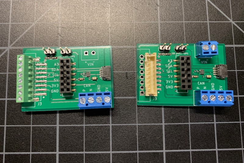
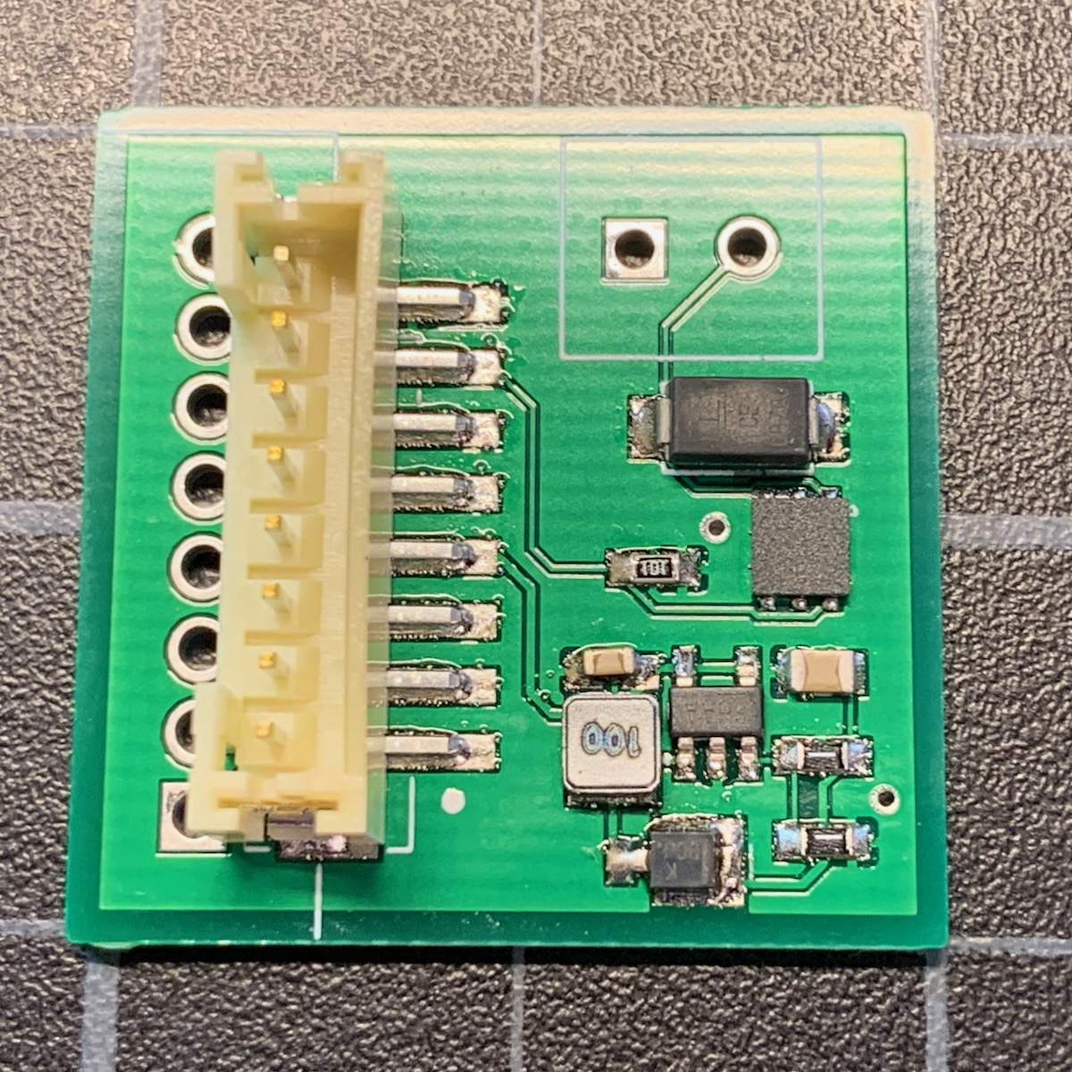
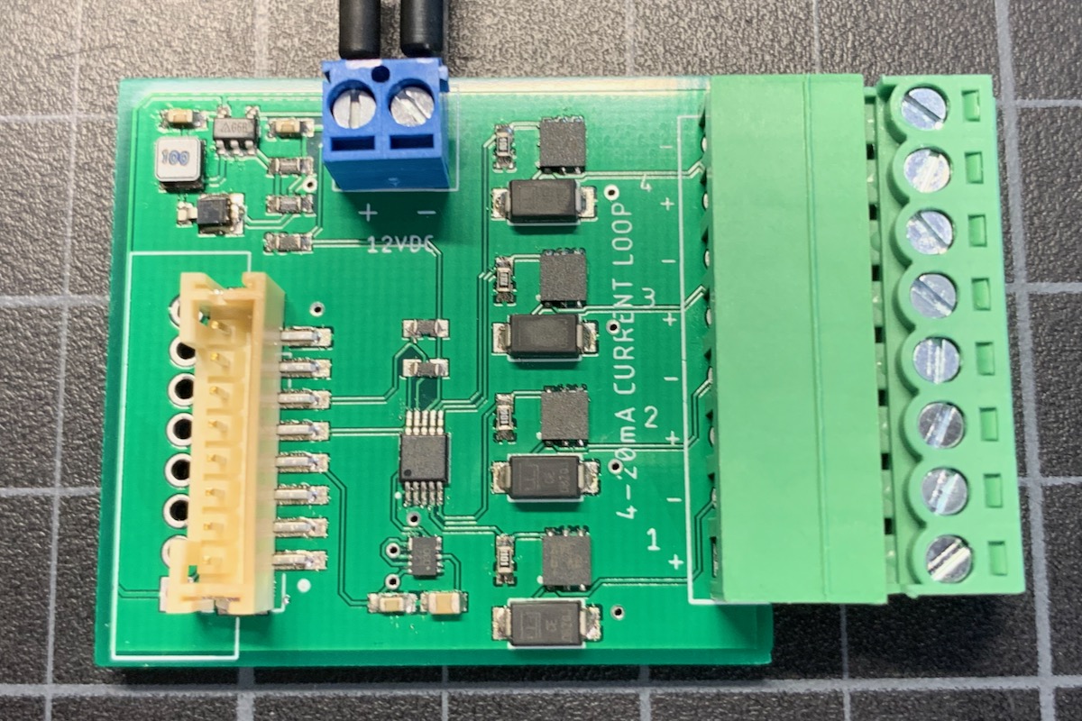
4-20 mA current loop sensors
These two app notes, AN020 Tracker 4-20mA Sensor Single and AN021 Tracker 4-20mA Sensor Quad show how to connect a 4-20 mA current loop sensor to the Tracker One M8 port.
The single port design can be powered by the built-in LiPo battery or USB and uses the built-in ADC on the nRF52840, available on the M8 connector. It includes a boost converter to 24VDC for the 4-20mA current loop. It includes over-current protection, limiting the 4-20mA loop to 30 mA.
The quad port design requires an external 12V power supply, but this power supply can also power the Tracker One. It includes a boost converter to 24VDC for the 4-20mA current loop and separate current limiters for each current loop. It uses an external I2C ADC connected to the M8 connector.
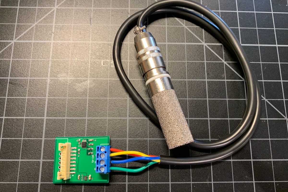
SHT3x Temperature and humidity sensor (5V I2C)
AN022 Tracker SHT3x Temperature/Humidity shows how to connect 5V I2C devices including the SHT30 and SHT31 temperature and humidity sensors to the Tracker One M8 connector and add data to location publishes. The board design should be compatible with all 5V I2C peripherals.