
P2 Evaluation Board
The P2 evaluation board is not a product and was only produced in limited quantities for testing.
This is a simple breakout board for Particle's P2 Wi-Fi module. It breaks out all of its pins via easy to use headers. The board features a USB port, a barrel jack power connector, buttons, and RGB LED as well as Feather, Grove, and Qwiic connectors for prototyping with external sensors, displays, etc..
The design for this board is open-source and can be found in P2 reference design in Github.
Description
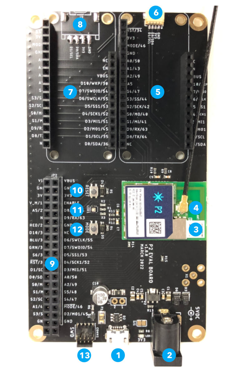
| Label | Description |
|---|---|
| 1 | USB |
| 2 | 5V Power In (optional) |
| 3 | P2 Module |
| 4 | External Wi-Fi and BLE antenna (optional) |
| 5 | Feather expansion connector |
| 6 | Qwiic I2C connector |
| 7 | Feather expansion connector |
| 8 | Grove expansion connector |
| 9 | Expansion header |
| 10 | RESET button |
| 11 | RGB LED |
| 12 | MODE button |
| 13 | SWD debugging connector |
If powering by USB, 500 mA is required. This a compatible with most USB hubs, computers, laptops, and chargers, but will not work with some low-power USB ports on some keyboards.
The P2 includes a built-in trace antenna that is used for both BLE and Wi-Fi. A U.FL connector is provided for an external antenna, if desired. The antenna selection must be made in software; the P2 will not automatically switch between built-in and external antennas. If using an external antenna, a dual-band (2.4 GHz and 5 GHz) antenna is required. The external antenna doesn't have to explicitly include BLE support, as the BLE frequencies are the same as 2.4 GHz Wi-Fi so all dual-band Wi-Fi antennas are compatible.
Building user firmware
As of the time of writing (June 2022), P2 firmware can only be compiled using the cloud compiler.
Using Particle Workbench
When using Particle Workbench, use the Particle: Launch CLI option from the Command Palette (Command-Shift-P or Ctrl-Shift-P). Then use the Particle CLI to generate a binary, as described in the next section.
Using the Particle CLI
From the Particle CLI, you can use a command such as:
particle compile p2 . --target 3.2.1-p2.3 --saveTo firmware.bin
Note that you must specify a target Device OS version when building for the P2. If an upgrade of Device OS is required, it will be updated OTA.
Using the Web IDE
From the Web IDE, select the Devices icon, then your P2 device, then target an appropriate firmware version, such as 3.2.1-p2.3 or 3.2.1-p2.2. If an upgrade of Device OS is required, it will be updated OTA.
Expansion connectors
Expansion header
If you are prototyping your own custom design you may want to use the 40-pin expansion header. It's a standard 20x2 female header, 0.1" pitch, that can accept male header pins or prototyping wires.

See the P2 Datasheet for details about the pins. The gold boxes indicate the P2 pin numbers.
Feather expansion

There are two socket for Feather accessory boards. These are only for use with displays, sensors, storage, etc..
You must not plug a Particle device such as an Argon or Boron in this socket, as the device may be permanently damaged.
This will work with most Feather boards, however:
- The P2 does not support ADC inputs A3, A4, and A5.
- The P2 does not work with Feather accessories that use SPI1 on the Argon or Boron D pins.
- Some pins have different names which may require minor source code modifications. This includes and code that used Argon or Boron pins A3, A4, A5, or D8.
The pinouts of the Feather accessory socket correspond to pinouts of the Photon 2. See the Photon 2 Datasheet and the Argon to Photon 2 migration guide for more information.
Some pins in the same positions are named differently between the Argon/Boron and the Feather accessory socket/Photon 2:
| Argon Name | P2 Feather Socket Name |
|---|---|
| A3 | A5 |
| A4 | S4 |
| A5 | S3 |
| D8 | D10 |
Additionally, D pin aliases D8 and higher are different, however these names are rarely used.

Qwiic connector
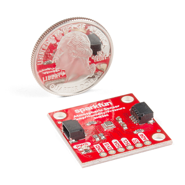
Qwiic is a 3.3V I2C standard developed by SparkFun and adopted by other manufacturers. It's also compatible with Adafruit Stemma Qt expansion devices. You can use this to add displays, sensors, etc. and multiple devices can be connected to a single Qwiic port, as accessory boards have two connectors for chaining multiple sensors.
Grove connector
The Grove connector allows Grove accessories to be added. Pins D0 and D1 are present on the connector. This allows the use of Grove I2C sensors.
If you are not using I2C elsewhere (Feather, Qwiic), you can use these pins as digital GPIO, or as analog inputs.
| Pin | I2C | Digital | Analog |
|---|---|---|---|
| GND | |||
| 3V3 | |||
| D0/SDA | SDA | D0 | A3 |
| D1/SCL | SCL | D1 | A4 |
SWD debugging connector
The P2 eval board has a 10 pin debug connector that exposes the SWD interface of the MCU. This can be used to program the bootloader, device OS, or the user firmware using any standard SWD tools including the Particle Debugger, Segger J/LINK, or other CMSIS-DAP debuggers. It can also be used for source-level debugging using Particle Workbench.
Note that SWD is shared with GPIO pins D6 and D7, and by default SWD is only enabled while the bootloader is running, immediately at boot, and when in DFU mode (blinking yellow). Only Debug builds in Workbench have SWD enabled in when user firmware is running.
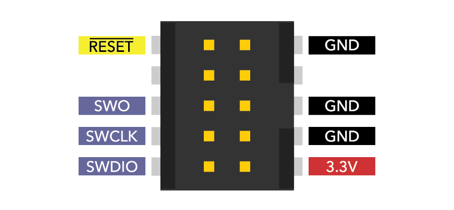
The SWO pin is not used on the P2.