
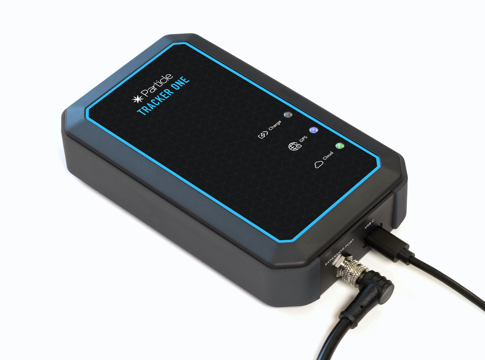
Tracker One

The Tracker One is a ready-to-go Particle gateway device with a Tracker SoM carrier board and weatherproof enclosure.
- Ready to go with IP67-rated enclosure.
- GNSS Antenna Onboard: convenient high-gain GNSS antenna for easy access to GNSS signals.
- Flexible Power Supply: easily add asset tracking to most devices. A wide 6-30V power supply copes with most power delivery systems. Also accepts 5V supply via USB-C. LiPo battery connector with charge LED. Supports up to 90V when connecting directly to the carrier board.
- High-precision Thermistor with accuracy to 1%.
- Extensible: IP67-rated M8 connector includes CAN Bus, UART, GPIO, and power for simple expansion.
- USB-C for flashing, debugging and power with higher charging rates than Micro-USB.
- RGB LED for use as both a user-configurable device as well as Particle status information.
Particle gateway device like the Monitor One and Tracker One are designed to be used off-the-shelf to interface to other devices and sensors using standard protocols such as CAN bus, I2C, and serial.
Model comparison
| ONE404 | ONE402 | ONE524 | ONE523 | |
|---|---|---|---|---|
| Region | NorAm | NorAm | EMEAA | Europe |
| EtherSIM | ✓ | ✓ | ||
| Supply Secure | ✓ | ✓ | ||
| Lifecycle | GA | Deprecated | GA | Deprecated |
- EtherSIM devices generally have a larger number of carriers and more may be added in the future
- NorAm: North America (United States, Canada, and Mexico)
- EMEAA: Europe, Middle East, Africa, and Asia (not all countries supported)
- See the Carrier list for specific carrier and country compatibility
- See the Supply secure FAQ for more information
- See Lifestyle stages for more information
Device OS support
For information on upgrading Device OS, see Version information. For the latest version shipped from the factory, see Manufacturing firmware versions page. See also Long Term Support (LTS) releases.
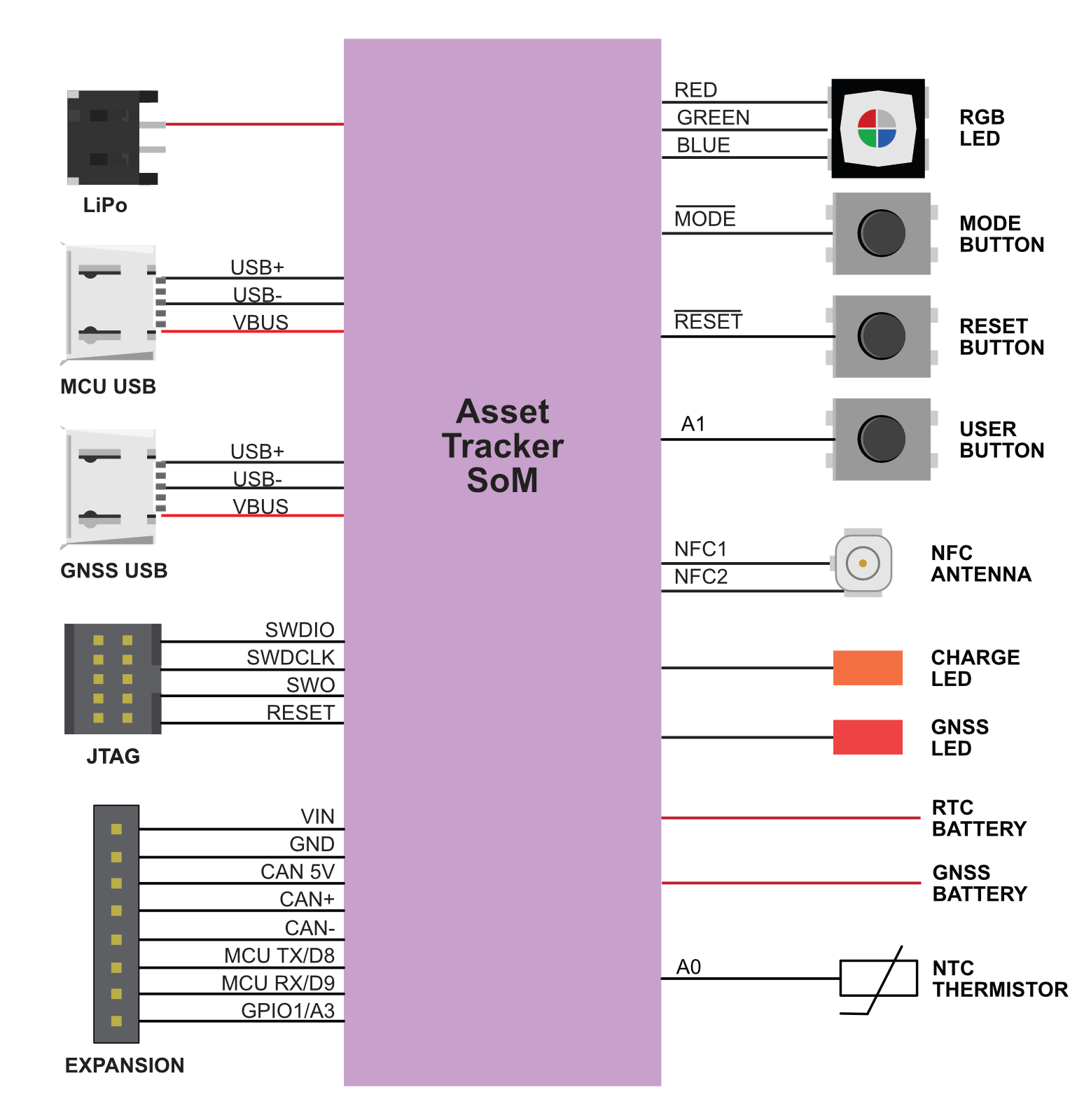
Block diagram
Description
| Num | ID | Description |
|---|---|---|
| 1 | GNSS Antenna | |
| 2 | Wi-Fi Antenna (mounted on side of case) | |
| 3 | NFC Antenna (mounted on lid) 1 | |
| 4 | Power and I/O connector (B8B-PH) | |
| 5 | BLE Antenna (mounted on side of case) | |
| 6 | LiPo Connector | |
| 7 | M8 8-pin male connector (mounted on side of case) | |
| 8 | USB-C2 | |
| 9 | NFC connector (connects to NFC antenna on lid) | |
| 10 | RGB Status LED | |
| 11 | GNSS LED | GNSS Status LED |
| 12 | CHRG | LiPo charge status LED |
| 13 | USER | User Button |
| 14 | RESET | RESET Button |
| 15 | MODE | MODE button |
| 16 | Cellular Antenna (mounted on side of case) | |
| 17 | USB-C switch3 | |
| 18 | Thermistor | |
| 19 | JTAG connector (not populated)4 |
1When disassembling the Tracker One, be careful when removing the lid. The NFC antenna and LiPo battery are mounted on the lid, and the NFC antenna cable is short. Carefully remove the NFC U.FL connector before fully removing the lid of the case. Reconnect to (9).
2The USB-C connector is normally connected to the nRF52840 MCU. It can be connected to the GNSS module by using the USB-C switch (17).
3The normal state is 1-4 OFF and 5-6 ON to connect the USB to the nRF52840. To connect the USB-C to the u-blox GNSS, turn 1-4 ON and 5-6 OFF. Disconnect the USB-C and the LiPo battery before changing the switch settings.
4The JTAG connector is not populated at the factory. The connector is a Samtec FTSH-105-01-F-DV-K 10 position (2x5), 1.27mm pitch.
Power and I/O connector (M8)
| M8 Pin | Function | Function | Function | I/O | Color |
|---|---|---|---|---|---|
| 1 | CAN_P / CANH | IO2 | Yellow | ||
| 2 | VIN3 | I | Red | ||
| 3 | Analog A3 | GPIO D3 | IO1 | White | |
| 4 | Serial1 RX | Wire3 SDA | GPIO D9 | IO1 | Green |
| 5 | Serial1 TX | Wire3 SCL | GPIO D8 | IO1 | Brown |
| 6 | CAN_5V4 | CAN_PWR | O | Orange | |
| 7 | CAN_N / CANL | IO2 | Blue | ||
| 8 | GND | Black |
The IP67 M8, 8-pin, male pins with threaded barrel connector is accessible from the outside of the enclosure.
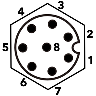
View as looking into the M8 connector on the outside of the enclosure.
Note: Version 003 and earlier of this datasheet had a different pin numbering for M8 connector that didn't match the connector manufacturer's numbering. Only the numbering has changed; the function of the pin at a given location is unchanged and the change should not affect existing designs.
1MCU GPIO is limited to 3.3V maximum.
2CAN Bus specifications can be found in the Tracker SoM datasheet.
36.0 to 30 VDC at 2A when using the M8 connector. 6.0 - 90 VDC at 2A when connecting directly to the board.
45V, 370 mA maximum. Controlled by the CAN_PWR GPIO.
Additional information on M8 cables and connectors can be found in the M8 Accessories Datasheet.
You must enable CAN_5V in order to use GPIO on M8 pins 3, 4, and 5 (A3, D9/RX/SDA, D8/TX/SCL) on the Tracker One. If CAN_5V is not powered, these pins are isolated from the MCU starting with version 1.1 of the Tracker One/Tracker Carrier Board (September 2020 and later). This is necessary to prevent an issue with shipping mode, see technical advisory note TAN002.
Note that CAN bus is differential and consists of two lines:
- CAN_P (positive), CANH (high), or CAN+
- CAN_N (negative), CANL (low), or CAN-
As the signals are differential you don't need to connect GND for CAN bus, but you do still need to connect it for Serial, I2C, or GPIO.
I/O characteristics (M8)
The three GPIO and port pins (A3/D3, RX/SDA/D9, TX/SCL/D8) have the following characteristics:
| Symbol | Parameter | Min | Typ | Max | Unit |
|---|---|---|---|---|---|
| VIH | Input high voltage | 0.7 xVDD | VDD | V | |
| VIL | Input low voltage | VSS | 0.3 xVDD | V | |
| VOH,SD | Output high voltage, standard drive, 0.5 mA, VDD ≥1.7 | VDD - 0.4 | VDD | V | |
| VOH,HDH | Output high voltage, high drive, 5 mA, VDD >= 2.7 V | VDD - 0.4 | VDD | V | |
| VOH,HDL | Output high voltage, high drive, 3 mA, VDD >= 1.7 V | VDD - 0.4 | VDD | V | |
| VOL,SD | Output low voltage, standard drive, 0.5 mA, VDD ≥1.7 | VSS | VSS + 0.4 | V | |
| VOL,HDH | Output low voltage, high drive, 5 mA, VDD >= 2.7 V | VSS | VSS + 0.4 | V | |
| VOL,HDL | Output low voltage, high drive,3 mA, VDD >= 1.7 V | VSS | VSS + 0.4 | V | |
| IOL,SD | Current at VSS+0.4 V, output set low, standard drive, VDD≥1.7 | 1 | 2 | 4 | mA |
| IOL,HDH | Current at VSS+0.4 V, output set low, high drive, VDD >= 2.7V | 6 | 10 | 15 | mA |
| IOL,HDL | Current at VSS+0.4 V, output set low, high drive, VDD >= 1.7V | 3 | mA | ||
| IOH,SD | Current at VDD-0.4 V, output set high, standard drive, VDD≥1.7 | 1 | 2 | 4 | mA |
| IOH,HDH | Current at VDD-0.4 V, output set high, high drive, VDD >= 2.7V | 6 | 9 | 14 | mA |
| IOH,HDL | Current at VDD-0.4 V, output set high, high drive, VDD >= 1.7V | 3 | mA | ||
| RPU | Pull-up resistance | 11 | 13 | 16 | kΩ |
| RPD | Pull-down resistance | 11 | 13 | 16 | kΩ |
- GPIO default to standard drive (2mA) but can be reconfigured to high drive (9mA) in Device OS 2.0.0 and later using the
pinSetDriveStrength()function.
The Tracker One has a TI TS3A5018 Quad SPDT Analog Switch on the three GPIO pins (A3, D9/RX/SDA, D8/TX/SCL). The switch is normally open, and is closed when the CAN_5V is powered. By default, Tracker Edge enables CAN_5V when in normal operating mode and turns it off during sleep, however this behavior can be changed by using enableIoCanPower() and enableIoCanPowerSleep() in the TrackerConfiguration object.
The circuit looks like this:
![]()
Because this is an analog switch, the nRF52840 current limitations, 2 mA in standard drive (the default), and 9 mA in high drive also apply on the M8 side of the analog switch. The switch is rated up to 300 MHz, higher than the highest UART or I2C baud rate. The 3.3V recommended maximum for GPIO also applies on the M8 connector.
The CAN bus has a separate hardware transceiver and is not considered to be GPIO and does not have a 3.3V limitation.
Carrier board power and I/O connector
The connector on the carrier board itself is a JST B8B-PH-SM4-TB(LF)(SN), 8-position, 2mm pitch, male pins, shrouded. The mating connector is the JST PHR-8. The female sockets are available plain, with leads, and in pre-manufactured ribbon cable formats.
| PHR-8 Pin | M8 Pin | Function | Color |
|---|---|---|---|
| 1 | 2 | VIN | Red |
| 2 | 1 | CAN_P | Yellow |
| 3 | 7 | CAN_N | Blue |
| 4 | 6 | CAN_5V | Orange |
| 5 | 5 | TX_SCL_D8 | Brown |
| 6 | 4 | RX_SDA_D9 | Green |
| 7 | 3 | A3 | White |
| 8 | 8 | GND | Black |
Additional peripherals
| Signal | Device OS | Description |
|---|---|---|
| THERM | A0 | NTC Thermistor |
| USER | A1 | USER button |
| GNSS_LOCK | A2 | GNSS lock indicator |
| GPIO1 | A3 | GPIO on power and I/O connector |
| MCU TX | TX | MCU serial TX, GPIO D8, Wire3 SCL |
| MCU RX | RX | MCU serial RX, GPIO D9, Wire3 SDA |
Note: While the USER button exists inside the Tracker One, the Tracker One is a sealed unit and opening it will void the warranty and may affect certifications, thus it is not practical to use. It can be used with the Tracker Carrier Board.
Powering the Tracker carrier board
There are several options for powering the carrier board:
The MCU USB connector (USB-C). If using a laptop with a USB-A to USB-C cable and a 500 mA USB port, you should also use the LiPo battery. With an true USB-C port and cable, or a 2A tablet charger, you can power only by USB.
The VIN connector (6 to 30 VDC at 2A on the M8 connector, or 6 to 90 VDC at 2A to the B8B-PH connector on the board). This is useful with an external power supply.
The LiPo connector. This is typically used with a LiPo battery.
USB connector
There is a single USB C connector on the carrier board. On the Tracker One, this exits the enclosure and is IP67 rated.
A set of DIP switches on the carrier board allow this port to be connected to either the MCU (normal) or u-blox GNSS (for firmware updates). The normal state is 1-4 OFF and 5-6 ON to connect the USB to the nRF52840. To connect the USB-C to the u-blox GNSS, turn 1-4 ON and 5-6 OFF. Disconnect the USB-C and the LiPo battery before changing the switch settings.
LED Indicators
The RGB LED default behavior is:
- Red breathing: Attempting to connect to the cellular network
- Yellow breathing: Connecting to the cloud, weaker cellular signal
- Green breathing: Connecting to the cloud, good cellular signal
- Yellow solid: Connected to the cloud, weaker cellular signal
- Green solid: Connected to the cloud, good cellular signal
Alternatively the LED can be configured to the typical Particle color scheme (blinking green, blinking cyan, breathing cyan) via device or cloud configuration. Custom device firmware can provide other color schemes if desired.
The CHRG LED indicates the charge status:
- Off: Not charging or no power
- On: Charging
- Blinking: Charge fault
- Flickering: No battery
The GNSS LED indicates the GNSS fix status:
- Off: GNSS is powered off.
- Blinking (1 Hz): Attempting to get a GNSS fix
- On: Has a GNSS fix.
Antennas
| Antenna | Location |
|---|---|
| GNSS | Carrier Board (faces top of case) |
| Wi-Fi | Left Side |
| BLE | Left Side |
| NFC | Top |
| Cellular | Right Side |
![]()
As the GNSS antenna faces the top of the case, you also want the top of the case facing the sky to the greatest extent possible. You will likely be be unable to get a GNSS lock with the top facing down.
Tracker One schematics
Peripheral details
Thermistor
The Tracker Carrier Board contains a 100K NTC thermistor, connected to A0. It is a Panasonic ERT-J1VR104FM connected high-side.
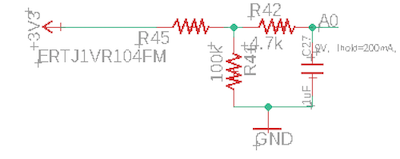
It can be read using the getTemperature() API. Note that this is the temperature on the board, within the enclosure, and will typically be several degrees warmer than the ambient temperature.
Design files
The Tracker Carrier Board in the Tracker One is open-source and the Eagle CAD design files are available in GitHub:
https://github.com/particle-iot/tracker-hardware
Mechanical specifications
Operating temperature
| Parameter | Minimum | Maximum | Units |
|---|---|---|---|
| Operating temperature | -10 | 60 | °C |
| Battery charging enabled | 0 | 50 | °C |
Dimensions and weight
| Parameter | Value | Units |
|---|---|---|
| Width | 88 | mm |
| Length (case only) | 146 | mm |
| Length (including M8 connector) | 154 | mm |
| Thickness | 33 | mm |
| Weight | 290 | g |
Case Dimensions (mm):
Bottom:
Maximum Carrier Board Dimensions (mm):
Note: The Tracker Carrier Board has a smaller bottom tab to provide space for the M8 connector.
3D models
3D models of the Tracker One enclosure are available in the hardware-libraries Github in step format.
Power consumption (Tracker One ONE402 and ONE404)
| Parameter | Symbol | Min | Typ | Peak | Unit |
|---|---|---|---|---|---|
| Operating Current (uC on, peripherals and radio disabled) | Istartup | mA | |||
| Operating Current (uC on, cellular connecting to cloud) | Icell_conn_cloud | mA | |||
| Operating Current (uC on, cellular connected but idle) | Icloud_idle | mA | |||
| Operating Current (uC on, cellular connected and transmitting) | Icloud_pub | mA | |||
| STOP mode sleep, GPIO wake-up | Istop_gpio | 911 | 1140 | 1530 | uA |
| STOP mode sleep, analog wake-up | Istop_analog | 920 | 1120 | 1480 | uA |
| STOP mode sleep, RTC wake-up | Istop_intrtc | 919 | 1130 | 1500 | uA |
| STOP mode sleep, BLE wake-up, advertising | Istop_ble_adv | 136 | 1190 | 2880 | uA |
| STOP mode sleep, BLE wake-up, connected | Istop_ble_conn | 772 | 1180 | 1790 | uA |
| STOP mode sleep, serial wake-up | Istop_usart | 993 | 1120 | 1510 | uA |
| STOP mode sleep, cellular wake-up | Istop_cell | 11.2 | 17.3 | 116 | mA |
| STOP mode sleep, IMU wake-up | Istop_imu | 850 | 1150 | 1590 | uA |
| STOP mode sleep, CAN wake-up | Istop_can | 981 | 1200 | 1600 | uA |
| STOP mode sleep, GPS wake-up | Istop_gps | 29.3 | 36.1 | 50.2 | mA |
| ULP mode sleep, GPIO wake-up | Iulp_gpio | 201 | 552 | uA | |
| ULP mode sleep, analog wake-up | Iulp_analog | 190 | 593 | uA | |
| ULP mode sleep, RTC wake-up | Iulp_intrtc | 188 | 558 | uA | |
| ULP mode sleep, BLE wake-up, advertising | Iulp_ble_adv | 270 | 2150 | uA | |
| ULP mode sleep, BLE wake-up, connected | Iulp_ble_conn | 258 | 990 | uA | |
| ULP mode sleep, serial wake-up | Iulp_usart | 638 | 842 | 1200 | uA |
| ULP mode sleep, cellular wake-up | Iulp_cell | 13.9 | 16.9 | 86.0 | mA |
| ULP mode sleep, IMU wake-up | Iimu_imu | 225 | 642 | uA | |
| ULP mode sleep, CAN wake-up | Ican_can | 75.3 | 270 | 631 | uA |
| ULP mode sleep, GPS wake-up | Iulp_gps | 28.0 | 35.3 | 49.5 | mA |
| HIBERNATE mode sleep, GPIO wake-up | Ihib_gpio | 161 | 564 | uA | |
| HIBERNATE mode sleep, analog wake-up | Ihib_analog | 151 | 557 | uA | |
| HIBERNATE mode sleep, external RTC wake-up | Ihib_extrtc | 151 | 562 | uA | |
| HIBERNATE mode sleep, IMU wake-up | Ihib_imu | 185 | 669 | uA | |
| HIBERNATE mode sleep, CAN wake-up | Ihib_can | 230 | 636 | uA |
1The min, and particularly peak, values may consist of very short transients. The typical (typ) values are the best indicator of overall power consumption over time. The peak values indicate the absolute minimum capacity of the power supply necessary, not overall consumption.
Current measurements taken at 3.6V via the battery input. For more information about measuring power usage, see power measurement.
Power consumption (Tracker One ONE523 and ONE524)
| Parameter | Symbol | Min | Typ | Peak | Unit |
|---|---|---|---|---|---|
| Operating Current (uC on, peripherals and radio disabled) | Istartup | 24.2 | 132 | 689 | mA |
| Operating Current (uC on, cellular connecting to cloud) | Icell_conn_cloud | 51.2 | 112 | 594 | mA |
| Operating Current (uC on, cellular connected but idle) | Icloud_idle | 50.9 | 60.2 | 197 | mA |
| Operating Current (uC on, cellular connected and transmitting) | Icloud_pub | 57.2 | 173 | 702 | mA |
| STOP mode sleep, GPIO wake-up | Istop_gpio | 778 | 1010 | 1390 | uA |
| STOP mode sleep, analog wake-up | Istop_analog | 740 | 995 | 1390 | uA |
| STOP mode sleep, RTC wake-up | Istop_intrtc | 758 | 993 | 1420 | uA |
| STOP mode sleep, BLE wake-up, advertising | Istop_ble_adv | 1050 | 2500 | uA | |
| STOP mode sleep, BLE wake-up, connected | Istop_ble_conn | 521 | 1050 | 1920 | uA |
| STOP mode sleep, serial wake-up | Istop_usart | 729 | 995 | 1390 | uA |
| STOP mode sleep, cellular wake-up | Istop_cell | 19.2 | 21.5 | 151 | mA |
| STOP mode sleep, IMU wake-up | Istop_imu | 741 | 1020 | 1460 | uA |
| STOP mode sleep, CAN wake-up | Istop_can | 884 | 1080 | 1490 | uA |
| STOP mode sleep, GPS wake-up | Istop_gps | 28.0 | 34.8 | 49.0 | mA |
| ULP mode sleep, GPIO wake-up | Iulp_gpio | 172 | 556 | uA | |
| ULP mode sleep, analog wake-up | Iulp_analog | 165 | 526 | uA | |
| ULP mode sleep, RTC wake-up | Iulp_intrtc | 164 | 561 | uA | |
| ULP mode sleep, BLE wake-up, advertising | Iulp_ble_adv | 228 | 1810 | uA | |
| ULP mode sleep, BLE wake-up, connected | Iulp_ble_conn | 231 | 1100 | uA | |
| ULP mode sleep, serial wake-up | Iulp_usart | 503 | 731 | 1169 | uA |
| ULP mode sleep, cellular wake-up | Iulp_cell | 18.6 | 20.9 | 212 | mA |
| ULP mode sleep, IMU wake-up | Iimu_imu | 194 | 534 | uA | |
| ULP mode sleep, CAN wake-up | Ican_can | 45.1 | 247 | 609 | uA |
| ULP mode sleep, GPS wake-up | Iulp_gps | 27.4 | 33.9 | 48.0 | mA |
| HIBERNATE mode sleep, GPIO wake-up | Ihib_gpio | 148 | 519 | uA | |
| HIBERNATE mode sleep, analog wake-up | Ihib_analog | 141 | 515 | uA | |
| HIBERNATE mode sleep, external RTC wake-up | Ihib_extrtc | 140 | 525 | uA | |
| HIBERNATE mode sleep, IMU wake-up | Ihib_imu | 178 | 544 | uA | |
| HIBERNATE mode sleep, CAN wake-up | Ihib_can | 222 | 608 | uA |
1The min, and particularly peak, values may consist of very short transients. The typical (typ) values are the best indicator of overall power consumption over time. The peak values indicate the absolute minimum capacity of the power supply necessary, not overall consumption.
Current measurements taken at 3.6V via the battery input. For more information about measuring power usage, see power measurement.
Country compatibility
| Country | Model | Technologies | Carriers |
|---|---|---|---|
| Albania | ONE524 | 2G, 3G, 4G | Eagle, Telekom, Vodafone |
| Algeria | ONE524 | 2G, 3G, 4G | Mobilis, Ooredoo |
| Aruba | ONE524 | 2G, 3G, 4G | Setar |
| Australia | ONE524 | 4G | Optus, Telstra, Vodafone |
| Austria | ONE524 | 2G, 4G | 3 (Drei), A1, T-Mobile |
| Bahrain | ONE524 | 2G, 4G | Zain |
| Bangladesh | ONE524 | 2G, 3G, 4G | Bangalink, GrameenPhone |
| Belarus | ONE524 | 2G, 3G, 4G | A1 |
| Belgium | ONE524 | 2G, 4G | Base, Orange, Proximus |
| Bosnia and Herzegovina | ONE524 | 2G, 3G | HT Eronet |
| Botswana | ONE524 | 2G, 3G, 4G | BeMobile |
| Brunei | ONE524 | 3G, 4G | DST |
| Bulgaria | ONE524 | 2G, 3G | A1, Telenor, Vivacom |
| Burkina Faso | ONE524 | 2G, 3G, 4G | Orange |
| Cabo Verde | ONE524 | 2G, 3G, 4G | CVMóvel, Unitel T+ |
| Cambodia | ONE524 | 2G, 3G | Metfone |
| Canada | ONE404 | M1 | Bell Mobility, Rogers Wireless, Telus |
| Chad | ONE524 | 2G, 3G, 4G | Airtel |
| Chile | ONE524 | 3G, 4G | Claro, Entel, Movistar |
| Congo (Brazzaville) | ONE524 | 2G, 3G, 4G | Airtel |
| Congo (Kinshasa) | ONE524 | 2G, 3G, 4G | Airtel |
| Côte d'Ivoire | ONE524 | 2G, 3G | MTN |
| Croatia | ONE524 | 2G, 3G, 4G | Hrvatski Telekom, Tele2 |
| Cyprus | ONE524 | 2G, 3G, 4G | MTN, PrimeTel |
| Czechia | ONE524 | 2G, 4G | O2, T-Mobile, Vodafone |
| Denmark | ONE524 | 2G, 4G | 3 (Tre), TDC, Telenor, Telia |
| Egypt | ONE524 | 2G, 3G, 4G | Etisalat, Orange |
| Estonia | ONE524 | 2G, 3G, 4G | Elisa, Tele2, Telia |
| eSwatini | ONE524 | 2G, 3G, 4G | MTN |
| Ethiopia | ONE524 | 2G, 3G, 4G | Ethio Telecom |
| Faroe Islands | ONE524 | 2G, 3G | Faroese Telecom, Vodafone |
| Finland | ONE524 | 2G, 4G | DNA, Elisa, Telia |
| France | ONE524 | 2G, 3G, 4G | Bouygues, Free Mobile, Orange, SFR |
| French Guiana | ONE524 | 2G, 3G | Digicel |
| Gabon | ONE524 | 2G, 3G, 4G | Airtel |
| Germany | ONE524 | 2G, 4G | O2, Telekom, Vodafone |
| Ghana | ONE524 | 2G, 3G, 4G | AirtelTigo, MTN, Vodafone |
| Gibraltar | ONE524 | 2G, 3G, 4G | Gibtel |
| Greece | ONE524 | 2G, 4G | Cosmote, Vodafone, Wind |
| Guinea | ONE524 | 2G, 3G, 4G | MTN |
| Guinea-Bissau | ONE524 | 2G, 3G, 4G | MTN |
| Guyana | ONE524 | 2G | Digicel |
| Hong Kong | ONE524 | 3G, 4G | CMHK, CSL, SmarTone |
| Hungary | ONE524 | 2G, 3G, 4G | Magyar Telekom, Telenor, Vodafone |
| Iceland | ONE524 | 4G | Nova, Siminn, Vodafone |
| Indonesia | ONE524 | 2G, 4G | Indosat, Telkomsel, XL Axiata |
| Ireland | ONE524 | 2G, 3G, 4G | 3 (Tre), Meteor, O2, Vodafone |
| Israel | ONE524 | 4G | Hot Mobile, Orange, Pelephone |
| Italy | ONE524 | 2G, 4G | TIM, Vodafone, Wind |
| Jordan | ONE524 | 2G, 3G, 4G | Zain |
| Kazakhstan | ONE524 | 2G, 3G, 4G | Beeline, K-Cell |
| Kenya | ONE524 | 2G, 3G, 4G | Airtel |
| Kuwait | ONE524 | 2G, 3G, 4G | Viva, Zain |
| Latvia | ONE524 | 2G, 4G | Bite, LMT, Tele2 |
| Liechtenstein | ONE524 | 2G, 3G, 4G | Mobilkom, Orange |
| Lithuania | ONE524 | 2G, 4G | Bite, Omnitel, Tele2 |
| Luxembourg | ONE524 | 2G, 4G | Orange, POST, Tango |
| Macao | ONE524 | 3G, 4G | CTM |
| Madagascar | ONE524 | 2G, 3G, 4G | Airtel |
| Malawi | ONE524 | 2G, 3G, 4G | Airtel |
| Malaysia | ONE524 | 2G, 4G | Celcom, DiGi, Maxis |
| Malta | ONE524 | 2G, 3G, 4G | Go Mobile, Vodafone |
| Mexico | ONE404 | M1 | AT&T, Telcel |
| Moldova | ONE524 | 2G, 3G, 4G | Moldcell, Orange |
| Mongolia | ONE524 | 2G, 3G | Mobicom, Unitel |
| Montenegro | ONE524 | 2G, 3G, 4G | Mtel, T-Mobile, Telenor |
| Morocco | ONE524 | 2G, 3G, 4G | Inwi, Medi Telecom |
| Mozambique | ONE524 | 2G, 3G, 4G | Vodacom |
| Myanmar | ONE524 | 2G, 3G, 4G | MPT, Telenor |
| Namibia | ONE524 | 2G, 3G, 4G | Telecom Namibia |
| Netherlands | ONE524 | 2G, 3G, 4G | KPN, T-Mobile, Vodafone |
| New Zealand | ONE524 | 4G | 2degrees, Spark, Vodafone |
| Nigeria | ONE524 | 2G, 3G, 4G | 9mobile, Airtel, Glo, MTN |
| Norway | ONE524 | 2G, 3G, 4G | TDC, Telenor, Telia |
| Pakistan | ONE524 | 2G, 3G, 4G | Mobilink, Telenor, Ufone, Warid |
| Palestine | ONE524 | 2G, 3G | Jawwal |
| Papua New Guinea | ONE524 | 2G, 3G | bmobile |
| Poland | ONE524 | 2G, 3G, 4G | Orange, Play, Plus, T-Mobile |
| Portugal | ONE524 | 2G, 3G, 4G | NOS, TMN, Vodafone |
| Qatar | ONE524 | 2G, 4G | Ooredoo, Vodafone |
| Romania | ONE524 | 2G, 4G | Orange, Telekom Romania, Vodafone |
| Rwanda | ONE524 | 2G, 3G | Airtel, MTN |
| Serbia | ONE524 | 2G, 3G, 4G | Telenor, VIP |
| Seychelles | ONE524 | 2G, 3G, 4G | Airtel |
| Sint Maarten | ONE524 | 2G, 3G | TelCell |
| Slovakia | ONE524 | 2G, 4G | O2, Orange, Telekom |
| Slovenia | ONE524 | 2G, 3G, 4G | A1, Mobitel |
| South Africa | ONE524 | 2G, 3G, 4G | Cell C, MTN, Vodacom |
| South Korea | ONE524 | 3G, 4G | KT, LG U+, SK Telecom |
| South Sudan | ONE524 | 2G, 3G | MTN |
| Spain | ONE524 | 2G, 3G, 4G | Orange, Telefonica, Vodafone, Yoigo |
| Sri Lanka | ONE524 | 2G, 4G | Dialog, Mobitel |
| Suriname | ONE524 | 2G, 3G | Telesur |
| Sweden | ONE524 | 2G, 4G | 3 (Tre), Tele2, Telenor, Telia |
| Switzerland | ONE524 | 3G, 4G | Salt, Sunrise, Swisscom |
| Taiwan | ONE524 | 4G | Chunghwa, FarEasTone, T Star, Taiwan Mobile |
| Tanzania | ONE524 | 2G, 3G, 4G | Airtel |
| Thailand | ONE524 | 2G, 3G, 4G | AIS, DTAC, True Move |
| Tunisia | ONE524 | 2G, 3G, 4G | Orange Tunisie, Tunisie Telecom |
| Uganda | ONE524 | 2G, 3G, 4G | Africell, Airtel, MTN |
| United Kingdom | ONE524 | 2G, 4G | 3, EE, O2, Vodafone |
| United States | ONE404 | M1 | AT&T, T-Mobile (USA), Verizon7 |
| Vietnam | ONE524 | 3G, 4G | MobiFone, Viettel, Vinaphone |
| Zambia | ONE524 | 2G, 3G, 4G | Airtel |
7Verizon in the United States is only supported on enterprise plans.
Ordering information
| SKU | Description | Region | Modem | EtherSIM | Lifecycle | Replacement |
|---|---|---|---|---|---|---|
| ONE404MEA | Tracker One LTE M1 (NorAm, EtherSIM), [x1] | NORAM | BG96-MC | ✓ | GA | |
| ONE404MTY | Tracker One LTE M1 (NorAm, EtherSIM), Bulk [x40] | NORAM | BG96-MC | ✓ | GA | |
| ONE523MEA | Tracker One LTE CAT1/3G/2G (Europe), [x1] | EMEAA | EG91-EX | GA | ONE524MEA | |
| ONE523MTY | Tracker One CAT1/3G/2G (Europe), Bulk [x40] | EMEAA | EG91-EX | GA | ONE524MTY | |
| ONE524MEA | Tracker One LTE CAT1/3G/2G (Europe, EtherSIM), [x1] | EMEAA | EG91-EX | ✓ | GA | |
| ONE524MTY | Tracker One CAT1/3G/2G (Europe, EtherSIM), Bulk [x40] | EMEAA | EG91-EX | ✓ | GA | |
| ONE402MEA | Tracker One LTE M1 (NorAm), [x1] | NORAM | BG96-MC | Deprecated | ONE404MEA | |
| ONE402MTY | Tracker One LTE M1 (NorAm), Bulk [x40] | NORAM | BG96-MC | Deprecated | ONE404MTY |
- EMEAA: Selected countries in Europe, Middle East, Africa, and Asia, including Australia and New Zealand. See the cellular carrier list for more information.
Certification
FCC interference statement
This device complies with part 15 of the FCC Rules. Operation is subject to the following two conditions: (1) This device may not cause harmful interference, and (2) this device must accept any interference received, including interference that may cause undesired operation.
This device must not be co-located or operating in conjunction with any other antenna or transmitter. This equipment has been tested and found to comply with the limits for a Class B digital device, pursuant to part 15 of the FCC Rules. These limits are designed to provide reasonable protection against harmful interference in a residential installation.
This equipment generates, uses and can radiate radio frequency energy and, if not installed and used in accordance with the instructions, may cause harmful interference to radio communications. However, there is no guarantee that interference will not occur in a particular installation. If this equipment does cause harmful interference to radio or television reception, which can be determined by turning the equipment off and on, the user is encouraged to try to correct the interference by one or more of the following measures:
- Reorient or relocate the receiving antenna.
- Increase the separation between the equipment and receiver.
- Connect the equipment into an outlet on a circuit different from that to which the receiver is connected.
- Consult the dealer or an experienced radio/TV technician for help.
To comply with FCC’s RF radiation exposure limits for general population/uncontrolled exposure, this device must be installed to provide a separation distance of at least 20cm from all persons.
WARNING: Any changes or modifications to this unit not expressly approved by the party responsible for compliance could void the user’s authority to operate the equipment.
This device must not be collocated or operating in conjunction with any other antenna or transmitter.
ISED interference statement
This device complies with Industry Canada license-exempt RSS standard(s). Operation is subject to the following two conditions:
- this device may not cause interference.
- this device must accept any interference, including interference that may cause undesired operation of the device.
Le présent appareil est conforme aux CNR d'Industrie Canada applicables aux appareils radio exempts de licence. L'exploitation est autorisée aux deux conditions suivantes:
- l'appareil ne doit pas produire de brouillage, et
- l'utilisateur de l'appareil doit accepter tout brouillage radioélectrique subi, même si le brouillage est susceptible d'en compromettre le fonctionnement.
This Class B digital apparatus complies with Canadian ICES-003.
Cet appareil numérique de la classe B est conforme à la norme NMB-003 du Canada.
This device and its antenna(s) must not be co-located or operating in conjunction with any other antenna or transmitter, except tested built-in radios.
Cet appareil et son antenne ne doivent pas être situés ou fonctionner en conjonction avec une autre antenne ou un autre émetteur, exception faites des radios intégrées qui ont été testées.
This equipment complies with IC radiation exposure limits set forth for an uncontrolled environment. This equipment should be installed and operated with minimum distance 20cm between the radiator & your body.
Cet équipement est conforme aux limites d'exposition aux rayonnements IC établies pour un environnement non contrôlé. Cet équipement doit être installé et utilisé avec un minimum de 20 cm de distance entre la source de rayonnement et votre corps.
EU declaration of conformity
We, Particle Industries, Inc., declare under our sole responsibility that the product, ONE523M, ONE524M, ONE523M-NB, and ONE524M-NB, to which this declaration relates, is in conformity with RED Directive 2014/53/EU and (EU) 2015/863 RoHS Directive 2011/65/EU (Recast).
The full text of the EU declaration of conformity is available at the following Internet address https://www.particle.io/.
Radiation Exposure Statement: This equipment complies with radiation exposure limits set forth for an uncontrolled environment.
The operating frequency bands and the maximum transmitted power limit are listed below:
- BLE 2402-2480MHz, 10dBm
- Wi-Fi 2.4GHz band 2412-2484MHz, 21.5dBm
- LTE B1 B3 B7 B8 B20 B28 704.5-959.3MHz 1710.7-2687.5 MHz, 25dBm
- WCDMA 882.4-957.6 MHz 1922.6-2167.4 MHz, 25dBm
United Kingdom
UKCA Conformity:
Radio Equipment Regulations 2017 (S.I. 2017/1206)
Certification documents
FCC (United States) - ONE402 ONE404 Tracker One NorAm
- FCC ID: 2AEMI-T40X
- Attestation 15 Subpart B, Class B (sDoC)
- Test report FCC Part 15 Subpart B, Class B (sDoC)
- RF exposure report FCC Part 2, Section 2.1091
- RF exposure test report FCC Part 2, Section 2.1091
- Test report FCC Part 15 Subpart C, Section 15.247
- Test report FCC Part 22
- Test report FCC Part 24
- Test report FCC Part 27
ISED (Canada) - ONE402 ONE404 Tracker One NorAm
- ISED: 20127-ONE40X.
- Certificate of Conformity
- Test Report RS-130
- Test Report RS-132
- Test Report RS-133
- Test Report RS-139
- Test Report RSS-247 Issue 2, RSS-Gen Issue 5
- RF Exposure Report
- ISED RF Exposure Report
- ICES-003 Issue 6:2019
- ICES-003 Issue 6:2019 Test Report
RoHS - ONE402 ONE404 Tracker One NorAm
CE (Europe) - ONE523 ONE524 Tracker One EMEAA
- Summary
- EN 300 328 Test Report (2.4 GHz ISM band) (updated 2022-11-15)
- EN 300 330 Test Report (NFC) (updated 2022-11-15)
- EN 303 413 Test Report
- EN 301 489 Test Report (updated 2022-11-15)
- EN 301 511 Test Report (GSM) (updated 2022-11-15)
- EN 301 908 Test Report (updated 2022-11-15)
- EN-55032, EN 55035, EN 301 498 Test Report (updated 2022-11-15)
- EN-60950-1 Test Report
- EN-62311 Test Report (updated 2022-11-15)
- EN-62311, EN-50665 Test Report (updated 2022-11-15)
- EN-62638-1 Test Report
- EN-62479, EN-50663 Test Report (updated 2022-11-15)
- RoHS 3.0 Test Reports
FCC (United States) - ONE523 ONE524 Tracker One EMEAA
The ONE523 and ONE524 are not FCC certified as the cellular modem does not support the cellular bands used in the United States. The ONE404 should be used instead.
ISED (Canada) - ONE523 ONE524 Tracker One EMEAA
The ONE523 and ONE524 are not ISED certified as the cellular modem does not support the cellular bands used in the Canada. The ONE404 should be used instead.
RoHS - ONE523 ONE524 Tracker One EMEAA
UKCA (United Kingdom) - ONE523 ONE524 Tracker One EMEAA
- UKCA Certification (updated 2022-11-15)
Product handling
ESD precautions
The Tracker SoM contains highly sensitive electronic circuitry and is an Electrostatic Sensitive Device (ESD). Handling an module without proper ESD protection may destroy or damage it permanently. Proper ESD handling and packaging procedures must be applied throughout the processing, handling and operation of any application that incorporates the module. ESD precautions should be implemented on the application board where the B series is mounted. Failure to observe these precautions can result in severe damage to the module!
Battery warning
CAUTION
RISK OF EXPLOSION IF BATTERY IS REPLACED BY AN INCORRECT TYPE. DISPOSE OF USED BATTERIES ACCORDING TO THE INSTRUCTIONS.
Disposal

This device must be treated as Waste Electrical & Electronic Equipment (WEEE) when disposed of.
Any WEEE marked waste products must not be mixed with general household waste, but kept separate for the treatment, recovery and recycling of the materials used. For proper treatment, recovery and recycling; please take all WEEE marked waste to your Local Authority Civic waste site, where it will be accepted free of charge. If all consumers dispose of Waste Electrical & Electronic Equipment correctly, they will be helping to save valuable resources and preventing any potential negative effects upon human health and the environment of any hazardous materials that the waste may contain.
Revision history
| Revision | Date | Author | Comments |
|---|---|---|---|
| pre1 | 2020 Apr 20 | RK | Preview Release |
| pre2 | 2020 May 12 | RK | Added partial dimensions |
| 001 | 2020 Jun 29 | RK | First release |
| 002 | 2020 Jun 30 | RK | CAN 5V is limited to 400 mA, not 500 mA |
| 003 | 2020 Jul 16 | RK | Corrected M8 pinouts |
| 004 | 2020 Aug 06 | RK | Corrected M8 pin numbering |
| 005 | 2020 Aug 09 | RK | Updated VIN voltages |
| 006 | 2020 Aug 10 | RK | Updated carrier board diagram |
| 007 | 2020 Sep 01 | RK | Added antenna diagram |
| 008 | 2020 Sep 08 | RK | Corrected USB connector description |
| 009 | 2020 Sep 25 | RK | Add battery warning |
| 010 | 2020 Oct 14 | RK | Add temperature range |
| 011 | 2020 Nov 05 | RK | Add power usage |
| 012 | 2020 Dec 09 | RK | CAN termination resistor is not present |
| 013 | 2021 Feb 03 | RK | Change M8 CAN output current to 370 mA |
| 014 | 2021 Feb 17 | RK | Tracker One v1.1 GPIO note, update schematics |
| 015 | 2021 Mar 15 | RK | Updated model, carrier, ordering information |
| 016 | 2021 Mar 23 | RK | Added FCC and ISED interference statements |
| 017 | 2021 Mar 29 | RK | D8 and D9 were reversed in some tables |
| 018 | 2021 Sep 10 | RK | Changed wording of peak vs. max current |
| 019 | 2022 Aug 29 | RK | Added EU declaration of conformity |
| 020 | 2022 Sep 16 | RK | Added UKCA conformity |
| 021 | 2022 Sep 23 | RK | Added pin drive strengh information |
| 022 | 2022 Oct 01 | RK | Added additional IO characterstic information |
| 023 | 2023 Jan 31 | RK | Add Device OS versions |
| 024 | 2024 Apr 23 | RK | Added links to certification documents |