
Tinkering with "Tinker" - Boron
You are viewing the Tinker documentation the Boron. To view the documentation for other devices, use the blue device selector below the Particle logo on the left side of the page.
The Tinker section of the Particle mobile app makes it very easy to start playing with your Particle device without writing any code. It's great for early development, learning, and prototyping. We'll learn to use it in the next few examples.
To get started, you'll need the following things:
Materials
- Hardware
- Your Particle device, brand new and out of the box!
- USB to micro USB cable
- Power source for USB cable (such as your computer, USB battery, or power brick)
- Your iPhone, Windows, or Android smartphone
- (2) Resistors between 220 Ohms and 1000 Ohms
- (1) LED, any color
- (1) Photoresistor or other resistance-based sensor, such as a Thermistor or Force-Sensitive Resistor
- Software
- Experience
- Connecting your Device with your smartphone or USB
Step One: Select Your Device
You've already connected your device. This means that when you open the Particle App, you'll see a screen like this:
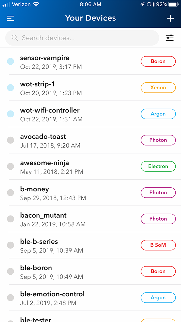
This person has a lot of devices, so the list is pretty crowded. As you can see, you can give your devices unique names to help you remember which is which.
Select the device you would like to Tinker around with by tapping on it.
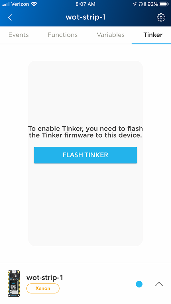
Troubleshooting Note: I have a device online, but it doesn't have Tinker firmware on it.
If your device does not have the Tinker firmware installed, you'll see a message similar to the one in the image below when you click on the Tinker tab on your device details screen.
 If you tap the "Flash Tinker" button, you'll see a confirmation screen letting you know that flashing tinker will overwrite the existing firmware on your device.
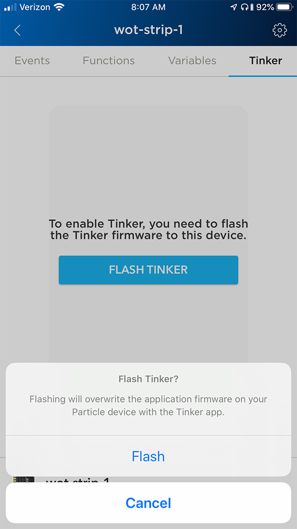 To walk through the following examples yourself, you'll want to reflash the Tinker firmware. Click the "Flash" option and continue once your device comes back online.
Step Two: Explore the Tinker App
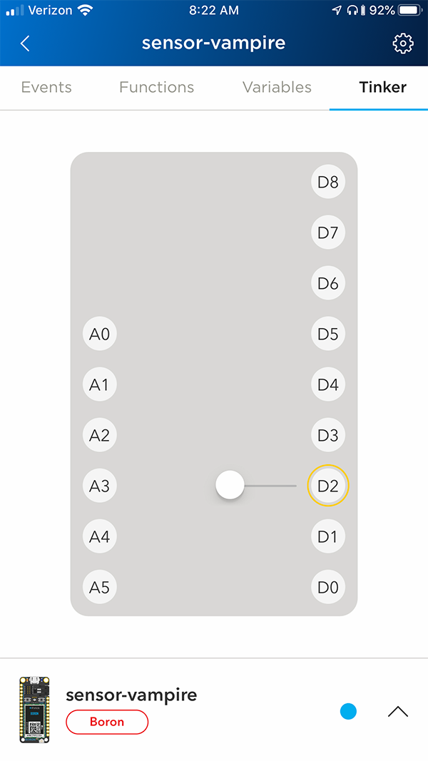
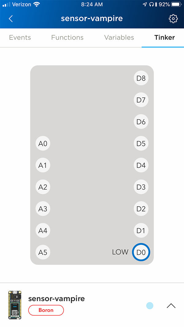
The app consists of 15 pins in vertical rows - 6 analog pins on the left, 9 digital pins on the right. These pins represent the 15 GPIO (General Purpose Input and Output) pins on your device.
To begin, tap any of the pins. A menu will pop up showing the functions that pin has available, tap a function name to select the pin functionality. You can reset the pin function by long-pressing it. Each pin can have up to four possible functionsIf you've ever programmed an Arduino microcontroller, you may recognize digitalWrite, analogWrite, digitalRead, analogRead, and their respective use-cases. The Tinker firmware is a pipeline for calling these very familiar Wiring functions from the cloud. More on this later.:
- digitalWrite: Sets the pin to HIGH or LOW, which either connects it to 3.3V (the maximum voltage of the system) or to GND (ground). Pin D7 is connected to an on-board LED; if you set pin D7 to HIGH, the LED will turn on, and if you set it to LOW, it will turn off.
- analogWrite: Sets the pin to a value between 0 and 255, where 0 is the same as LOW and 255 is the same as HIGH. This is sort of like sending a voltage between 0 and 3.3V, but since this is a digital system, it uses a mechanism called Pulse Width Modulation, or PWM. You could use analogWrite to dim an LED, as an example.
- digitalRead: This will read the digital value of a pin, which can be read as either HIGH or LOW. If you were to connect the pin to 3.3V, it would read HIGH; if you connect it to GND, it would read LOW. Anywhere in between, it'll probably read whichever one it's closer to, but it gets dicey in the middle.
- analogRead: This will read the analog value of a pin, which is a value from 0 to 4095, where 0 is LOW (GND) and 4095 is HIGH (3.3V). All of the analog pins (A0 to A5) can handle this. analogRead is great for reading data from sensors.
In other words, Tinker lets you control and read the voltage of the pins on your device. You can choose to send a lot of voltage to an LED to light it up, or read the voltage at a sensor.
Now for some examples!
Step Three: digitalWrite
The simplest thing we can do with Tinker is to turn the D7 LED on and off.
To turn on the LED, tap the D7 pin on the mobile app.
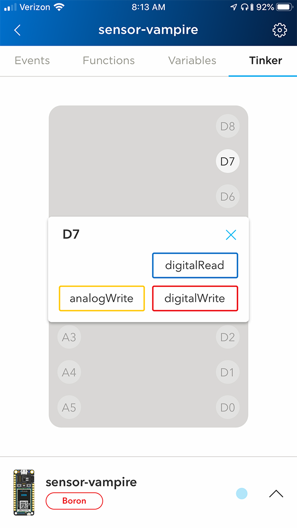
Then tap digitalWrite to let it know that you want to send high or low voltage to that pin.
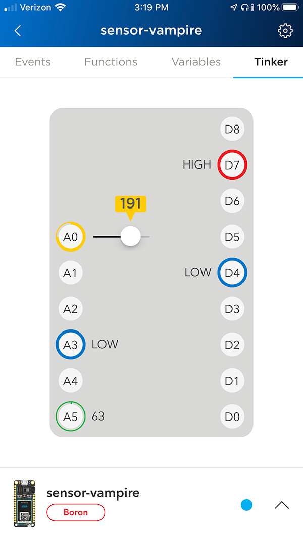
You'll see a screen like the one above. Try tapping the D7 pin on the screen again.
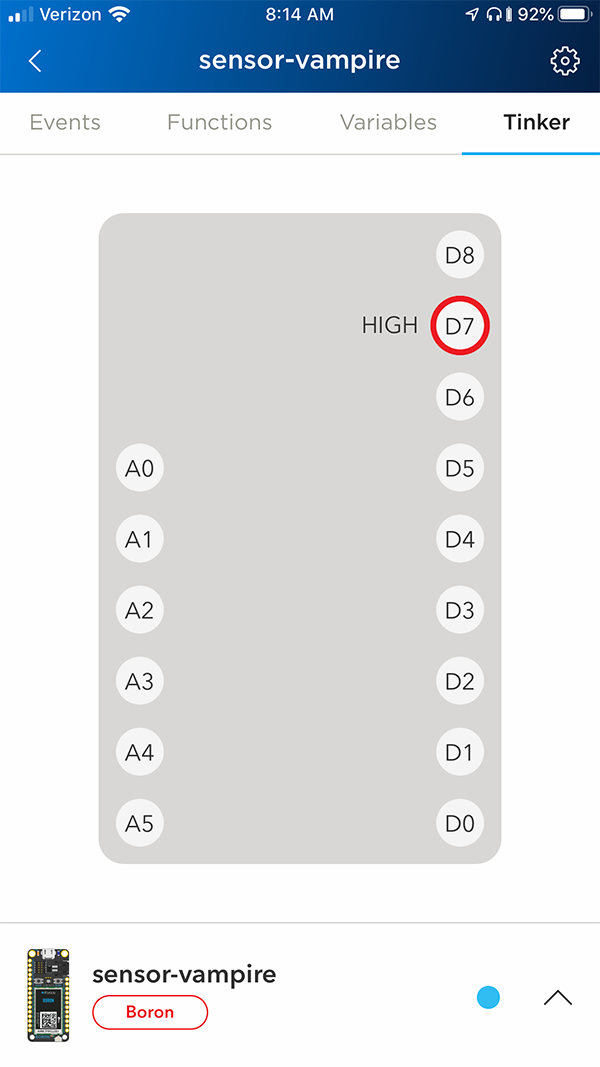
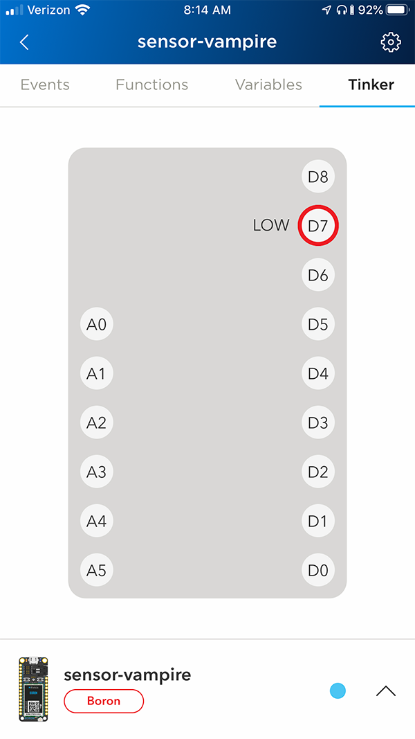
It will change its status to HIGH and your device's D7 LED will turn on. Tapping it again will change the status to LOW and the LED will turn off.
digitalWrite only has two options: HIGH and LOW. When we speak to our pins digitally, we can only send the maximum voltage or no voltage. That's great for when you only need two settings-- like if you had a light switch that could only go on and off, or locks that could only be open or closed. For everything in between, we use analogWrite.
Step Four: analogWrite
In this example, we'll plug an LED into D2 and change its brightness with analogWrite. (D2 is a PWM pin.A Pulse Width Modulation (PWM) output is a digital output that can be filtered through various means to create a pseudo analog output. It is possible to analogWrite to D0 through its PWM functionality.
Wire up your LED with one of your resistors. Connect the longer (anode) leg of the LED to pin D2 and the shorter (cathode) leg to GND via a resistor.
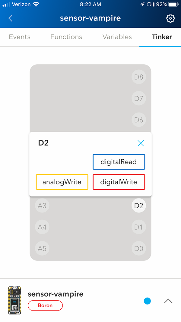
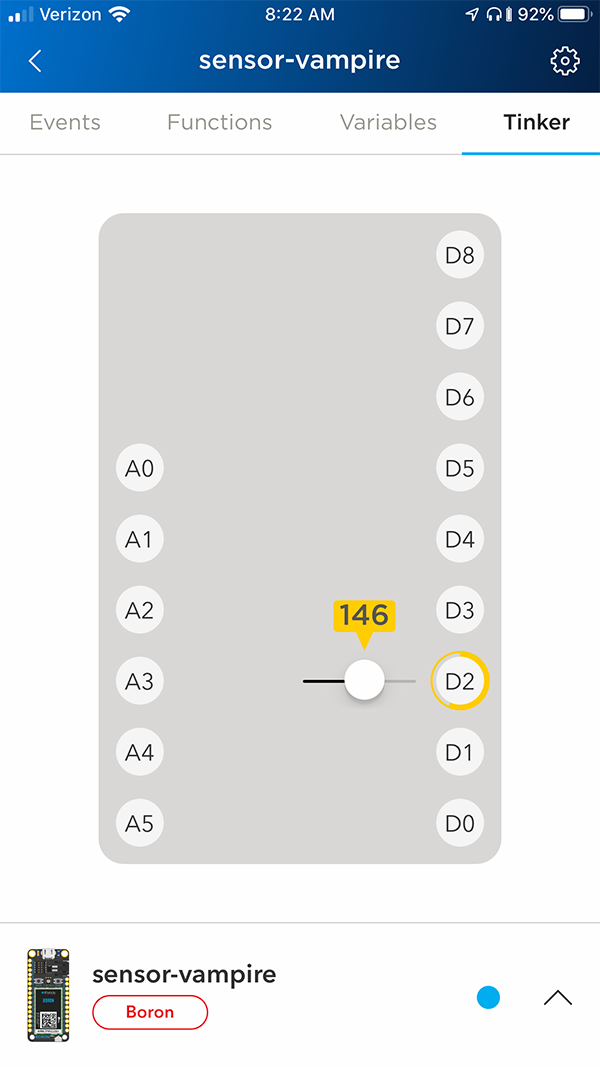
Then, pull up your mobile app and select D2 this time. Instead of digitalWrite, select analogWrite.
You should now be able to set the D2 pin to any number between 0 and 255.
It basically divides the maximum voltage by 255 and allows us to set the slider to any fraction of the voltage between minimum and maximum. Pretty cool, right?
By sliding and releasing the slider, you should be able to see the LED dim and glow at different levels.
If we wanted to, we could also switch modes and digitalWrite this LED to turn it on or off. To change the function of the pin, simply tap and hold on the pin, and the function select menu will come back up.
Step Five: digitalRead
We can also use Tinker to check to see if a pin is on or off. digitalRead is great for checking things that only have two states-- switches and buttons for example.
In this case, we're going to do the simplest thing possible and simply use one wire to change the voltage of the D0 pin. Plug a wire or resistor to connect D0 and 3V3.
As you can see, one side of the wire is plugged into 3V3 and the other is plugged into D0. 3V3 sends the maximum voltage out. We've plugged it into D0, so D0 is receiving the maximum voltage.
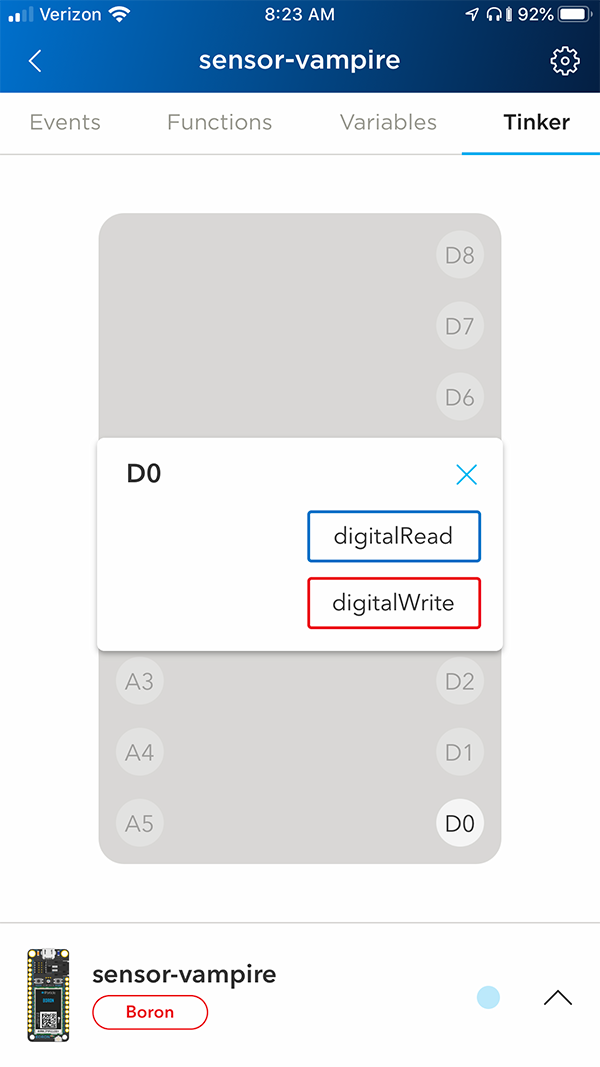
Let's read that. Go into your mobile app. Press and hold D0 to reset it. After it goes blank, tap it again and select digitalRead.
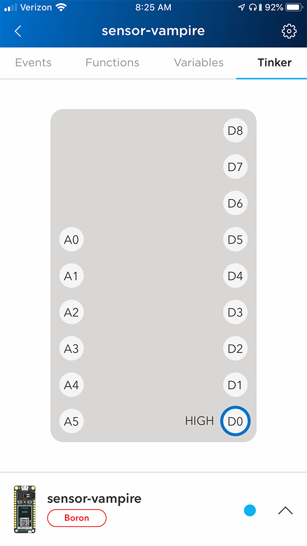
If your wire is plugged in, you'll see the word HIGH next to the D0 pin. Now unplug the wire and tap the D0 pin on the mobile app once more. Now the pin will say LOW.If you don't get LOW right away, give it a moment. There is still some residual voltage hanging out in the pin, but in a second that will disperse and it should read as LOW.
Step Six: analogRead
If we want to read a sensor, like a temperature or light sensor, we will need our device to give us more details than than just "It's on!" or "It's off!" When you want to read a value between LOW and HIGH, use analogRead.
Plug in a sensor. In this example, we'll use a photoresistor. You can use any resistor for this; a larger resistor (like 10K Ohms) will give you a wider range of values whereas a smaller resistor (like 330 Ohms) will give you lower range of values. Connect the Photoresistor between A0 and A5. Then, connect the resistor between A0 and GND.
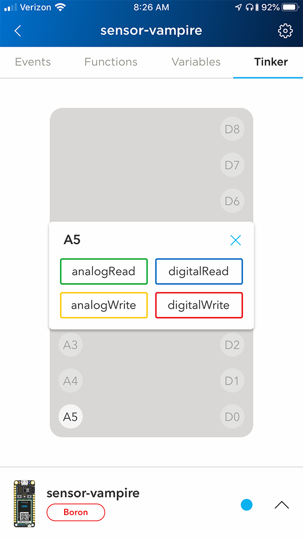
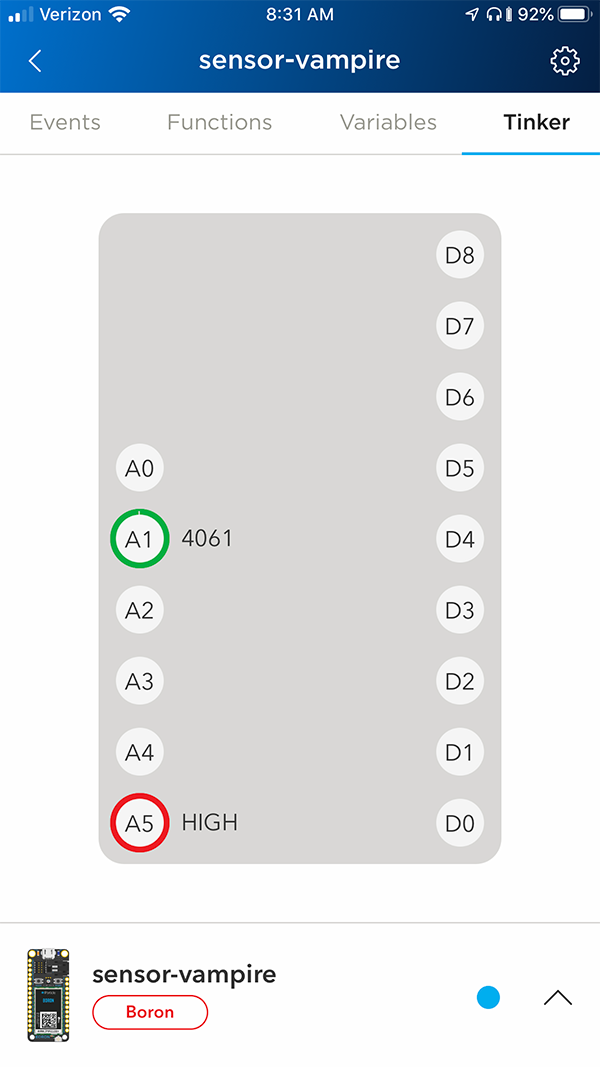
Tap the A5 pin and set it to digitalWrite and HIGH.
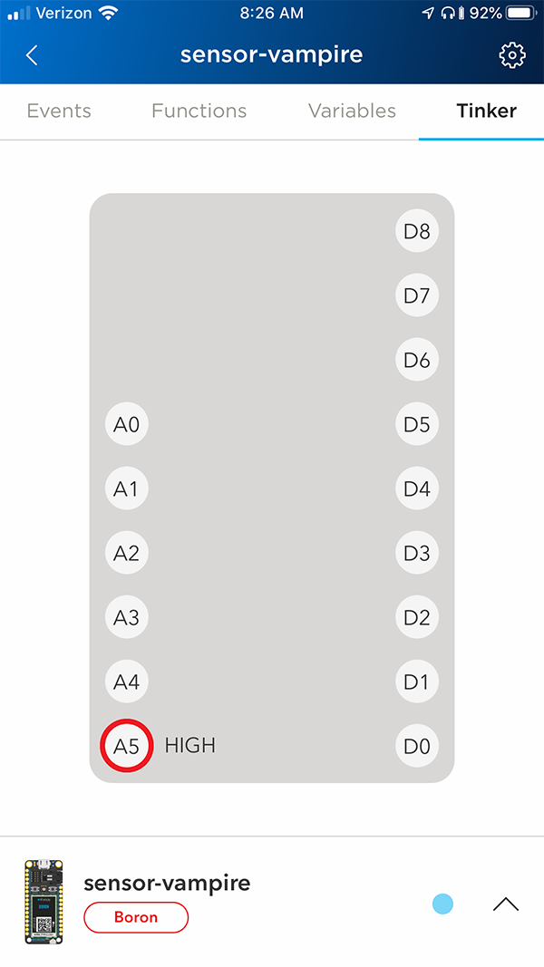
This essentially gives us a consistent power source from A5 that will go to our photoresistor. (We are doing this because sometimes an on-board power source like 3V3 has small fluctuations in power that could affect our photoresistor readings.)
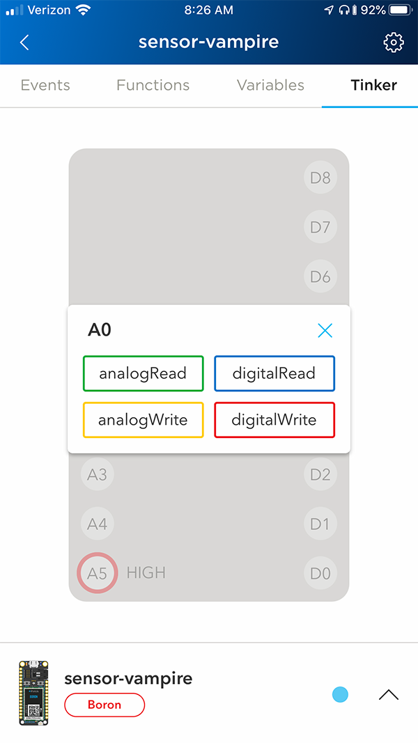
Now tap A1 and set it to analogRead.
Hold your breadboard with the photoresistor on it up to a light source and tap A1 again to get the reading of the photoresistor. Now cover the photoresistor and tap A1 again. See the difference?
You can try testing different kinds of light, or you can even swap out your photoresistor for another kind of fluctuating resistor like a thermistor or a force sensitive resistor.
When you're ready, let's move on to putting your own firmware on your Particle device using the web IDE.