
Console
The Particle Console is your centralized IoT command center. It provides interfaces to make interacting with and managing Particle devices easy. This guide is divided into two main sections, tools for developers and tools to manage product fleets.
Note: The Console does not work in Microsoft Internet Explorer including Edge. Please use another browser, such as Chrome or Firefox, to access the Console. If you're experiencing rendering issues, turn off any ad blocking extensions you may be using.
Demo
You can explore a live demo environment with a continuously operating device fleet, no hardware or setup required!
Visit the demo site for instant access.
Developer tools
While actively developing an IoT project or product, the Console offers many helpful features to make prototyping a breeze. See the last time a device connected, debug a firmware issue by observing event logs, set up a webhook to send data to an external service, and more.
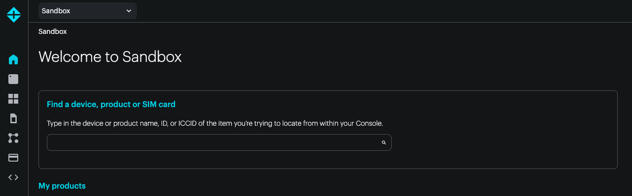
Search
The console makes it easy to search for a device from its Device ID (24-character hex code), serial number, name, or ICCID. You can also search for a product by name.
This can be done at the top level of your sandbox to search your sandbox and all organizations you have access to. There is also a search at the top level of each organization to search only that organization.
Devices
The Devices page allows you to see a list of the devices associated with your account. Here, you can see specific information about each device, including it's unique Device ID, it's name, the type of device, the last time it connected to the Particle cloud, and whether or not the device is currently online.
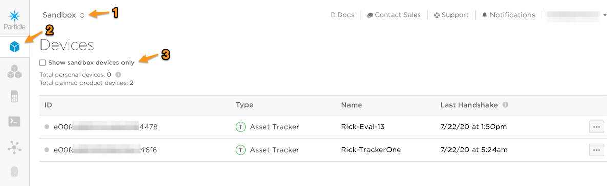
When Sandbox (1) is selected, you will see the devices in your personal sandbox, vs. your basic or enterprise organization.
Clicking the Devices icon (2) shows the Device List.
If the Show sandbox devices only checkbox (3) is not checked, then the list will be like the old, pre-checkbox, behavior and will show devices that are claimed to your account, both in your free developer sandbox as well as product devices in free, basic, and enterprise organization products.
When checked, the list will only include non-product devices claimed to your account in the free developer sandbox.
- Total personal devices is the number of non-product devices in your free developer sandbox.
- Total claimed product devices is the total number of devices claimed to your account that are in a product.
The 100-device limit in the free plan is the total of the devices claimed to your account in the developer sandbox, plus all devices in any free plan products that you are the owner of.
You can also take certain actions on devices from this view, such as renaming the device and unclaiming it from your account.
Unclaiming a cellular device removes it from your account, but does not stop billing. As the claiming status and SIM are separate, you must also pause or release ownership of your SIM to stop billing.
Event logs
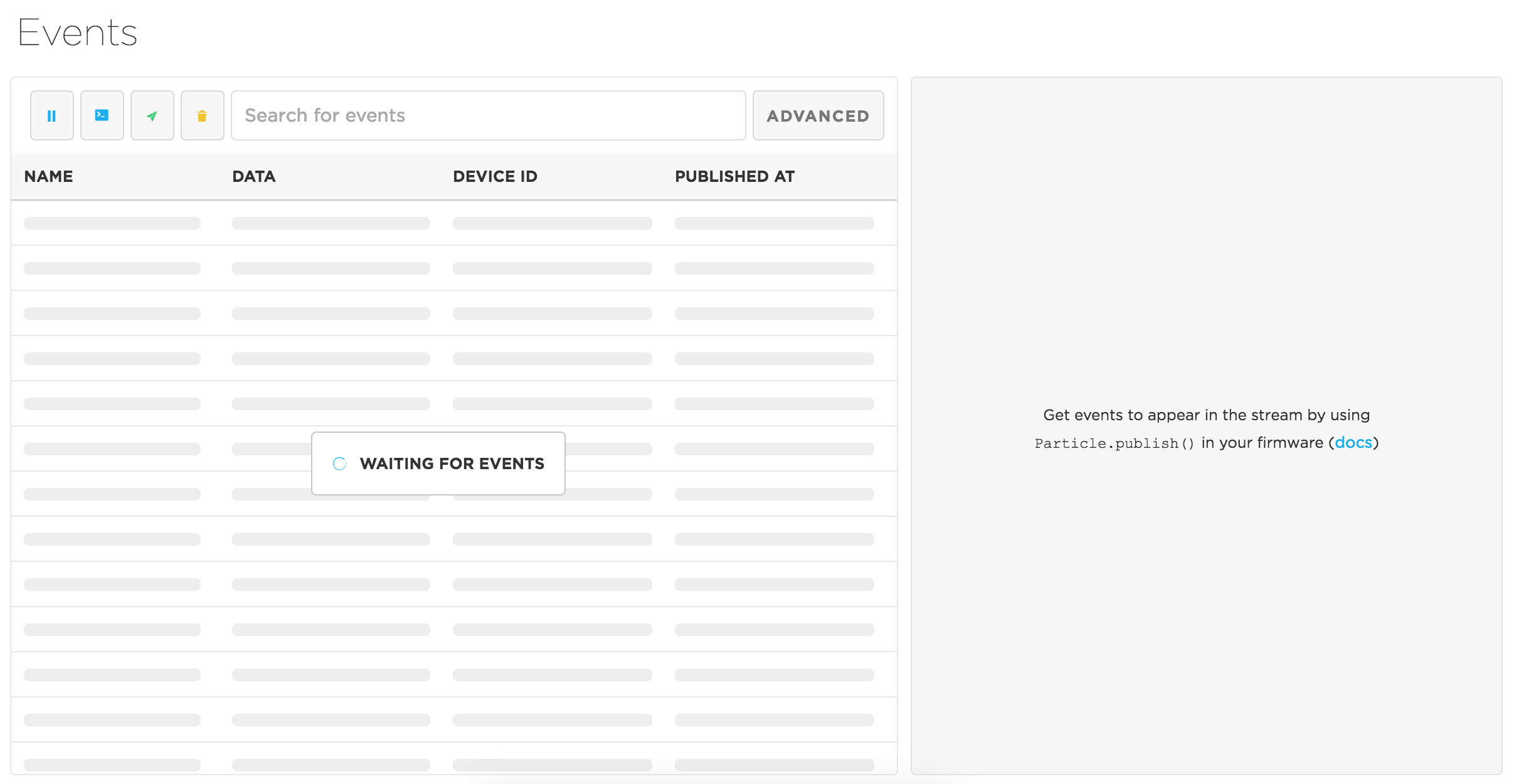
The Logs feature provides a clean interface to view event information in real-time, just from your devices. We're hoping that this is handy both while debugging code during development, and checking out recent activity on your device once you power-on your finished project. Tailored around improving the experience of browsing logs, the page provides a handful of tools, like filtering, modifiers which enable you to narrow down your search for events, making it easier to view only the data that is relevant to you. In this view, you'll only see events that come in while the browser window is open.
To visit the page go to https://console.particle.io/events
Logs
The left side of the page contains a real-time log of events passing through the cloud. You'll get the name, data, timestamp and the device name associated with each event as it comes in. Oh Yeah! And, if you click on the event, you can see the event data.
Exporting events
The Event Viewer Tool can be used if you want to export events to a file or spreadsheet.
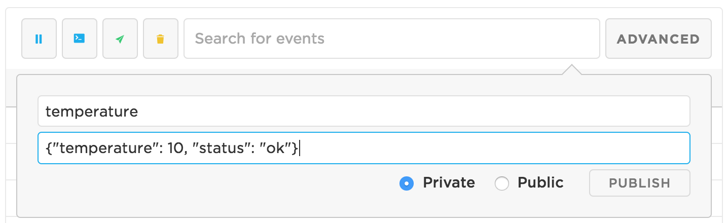
How to publish events
Publishing events can be achieved in multiple ways:
- Using
particle.publishin firmware (docs) - Using Particle API JS's
publishEvent(docs) - Using the Publish event button in the Event Logs page:
Filtering the events
Filters let you narrow down your search and only see events that are relevant.
You can filter the events by writing anything in the input. Your query will be compared with the event name, data, publisher, and date.
Modifiers
Besides writing in the input, you can use modifiers to narrow down your search even further. You can see the list of modifiers by pressing the Advanced button.
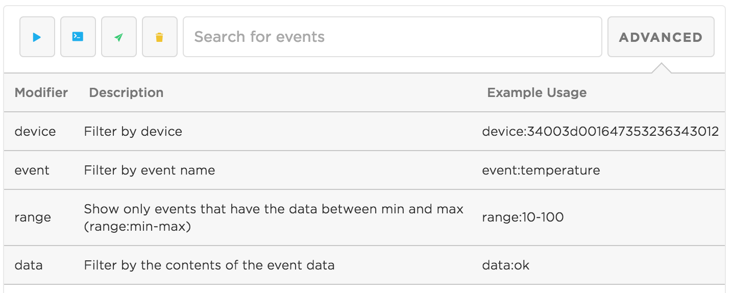
deviceFilter by device ID (example:device:34003d001647353236343012). Thedevicemodifier is not usable when viewing a device's individual page, as the stream is already listening only for events coming from that device.eventFilter by event name (example:event:status)rangeOnly show events that have a number value between min and max (range:min-max, example:range:20-100)dataFilter by data (example:data:device-is-ok)
Modifiers can be grouped: device:34003d001647353236343012 event:temperature range:30-50
Note: Having multiple modifiers of the same type is not yet supported (you can not filter by 2 device IDs)
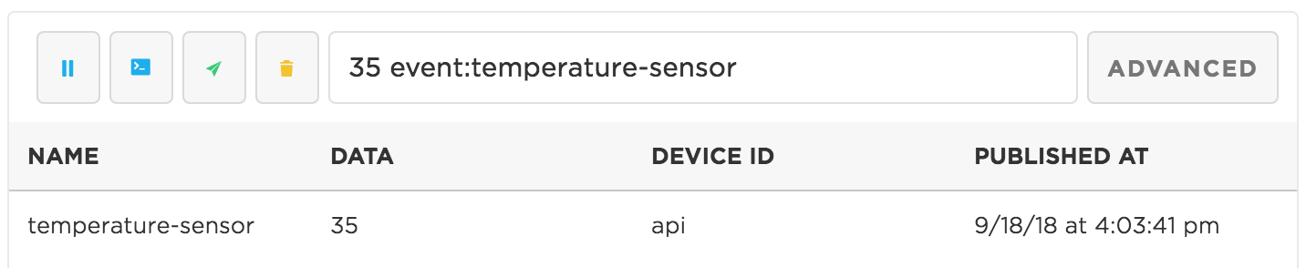
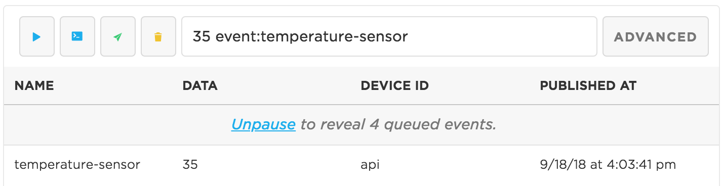
You can combine modifiers with a query. In this example, we combine the query '35' with the modifier 'event:temperature'. The page will only show events named temperature that have 35 as their data.
Viewing event data
To view more details about an event, click on it. If the event data is a valid JSON string, it will be displayed in a way that makes it easier to read and understand.
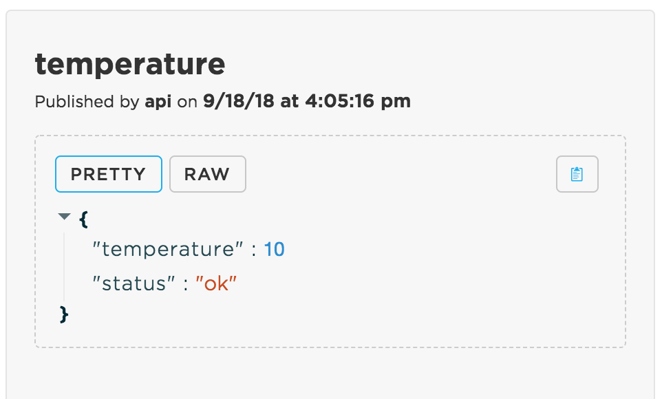
To view the raw version of the JSON, click on the RAW button.
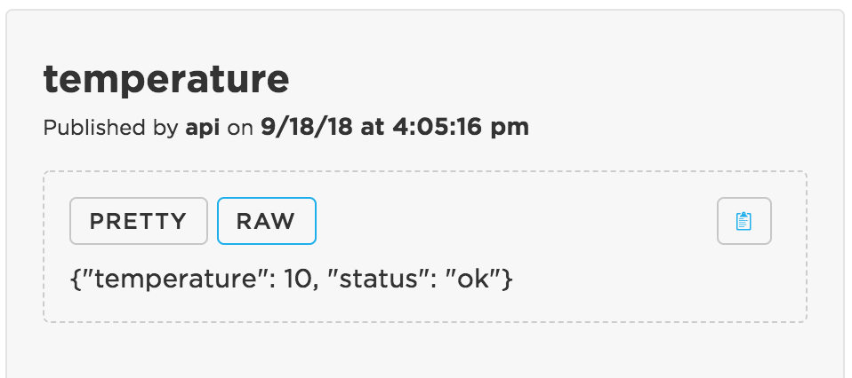
You can copy the data to the clipboard if you click on the copy button.
Note: You can also navigate through the event list by using the up and down arrow keys
Clearing the event logs
You can empty the list of received events by pressing on the Clear button.
Pausing the event stream
If lots of events are coming through, you can put events in a queue by clicking on the Pause button. This should help you navigate through the list of events that you have already received.
To make the events from the queue visible click on the Play button.
Integrations
Integrations allow you to send data from your Particle devices to external tools and services. The Console provides an interface to create, view, edit, and delete Particle integrations.

For more information on how to start using integrations, you should check out:
Configuration
Configuration is a platform‑wide capability for Particle. Configuration is the control plane for tailoring how devices, cloud, and applications behave, used to solve real-life problems like modem behavior and operating system level radio configuration, as well as to align user applications needs from any vertical or use case.
Configuration scales from organization‑wide defaults, to product‑level settings, to device‑specific overrides where appropriate.
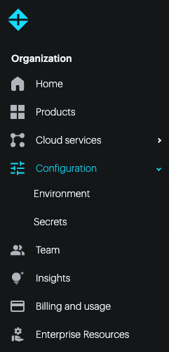
If you have access to an organization (basic, plus, or enterprise), you can set environment variables at the organization level in the Organization - Configuration - Environment section.
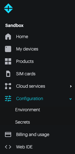
You can also set environment variables in Sandbox - Configuration - Environment section.
Additionally, both sandbox and organization products have their own Environment configuration.
For more information, see:
- Environment: lightweight, non‑secret name - value pairs that shape the runtime environment. They are ideal for fast, system level adjustments (endpoints, feature flags, polling intervals) without changing firmware. Available in the cloud and in the firmware.
- Secrets: secure, organization‑scoped values that integrations and logic can reference securely.
Billing & usage
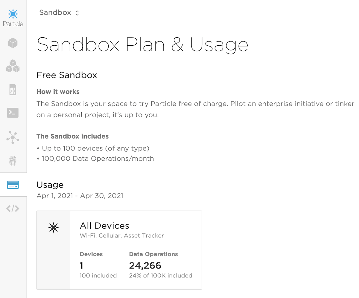
The Billing & Usage page shows billing information and data usage (data operations and cellular).
All accounts have a personal sandbox on the free plan. The sandbox can include up to 100 cellular and Wi-Fi devices (in any combination, not to exceed 100 total), free of charge. For the basic plan, this is in addition to devices included in your basic plan blocks.
From this page you can view the total number of devices and data operations consumed by your free sandbox devices.
For users who are Administrators of an organization, selecting the organization then Billing & Usage icon shows the usage for all products within the organization.
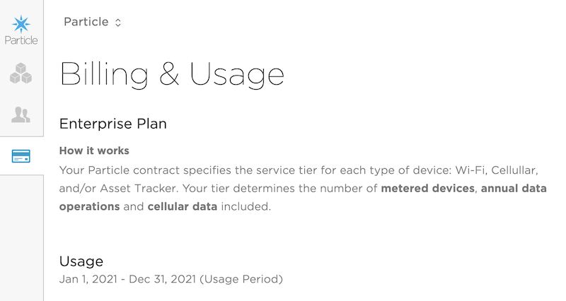
In the Basic and Enterprise plans, usage is divided by the class of devices. For example: Wi-Fi and Cellular:
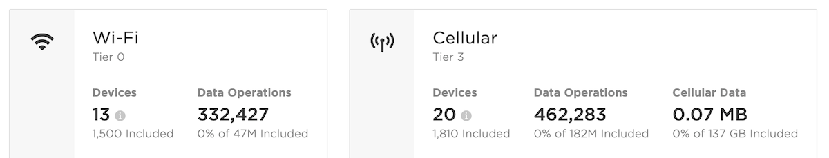
These panels turn yellow at 70% of your plan limits, and red when the limits have been reached.
You can also quickly view your usage from the popup under your email address in the upper-right corner of the console window.
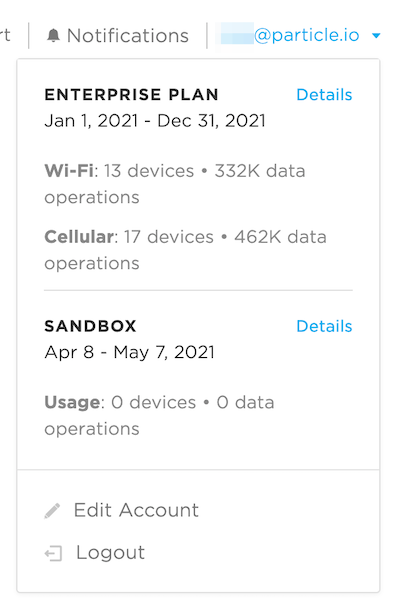
The numbers of devices and data operations will be updated within a half hour. Cellular data usage may be delayed for up to a week.
Historical data
At the bottom of the Billing & Usage panel you can request a data usage report:
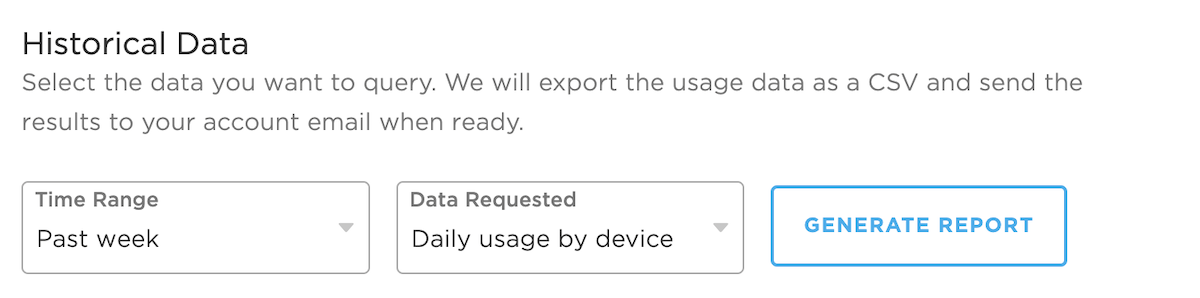
- Time Range: Past week, Past month, Past 3 months, Past year
- Data Requested: Data usage by device, Data usage by product
It will take several minutes to generate the data, and you will be emailed a csv file when done.
This option is also available for organization administrators in the organization Billing & Usage panel.
Billing limits
You will receive warnings by email, and as a pop-up, and in the Billing & Usage tab in the console at 70%, 90%, and 100% of the allowable data operations.
In the free plan, once you reach the 100% limit you have three days to switch the the Basic plan, or data will be stopped until the end of your billing month. It will automatically resume on the free plan at the beginning of the next billing month, still on the free plan, if you do not upgrade.
In the basic plan, once you reach the 100% limit an additional block will be added to your plan. Starting at the next billing month your plan will include these additional block(s) and you will be billed accordingly. There is no additional charge at the time of the overage; it occurs only on the next billing cycle.
Upgrading to the basic plan
Following the link from the emails or Billing & Usage page leads to a contact form to initiate the upgrade process. A representative will contact you by telephone to complete the upgrade process to basic plan.
When you upgrade to the basic plan, you will get an organization, which is the collection of products and accounts in your plan. The usage limits in the basic plan apply monthly across all products of the same type in your organization. Some limits vary between cellular, Wi-Fi, and tracker products.
Additionally, all organization members still have a private sandbox in their account and can still have their own 100 free devices that do not count against your basic plan limits.
If you already have your devices in a product, the entire product can be moved into your basic organization without affecting the customers, access tokens, or cloud API endpoints, so this should be a relatively easy transition.
Cellular usage
To view detailed cellular usage information for SIMs in a product you can use the cellular usage tool.
Product tools
For many using Particle, the end-goal is to move from a single prototype to a professional deployment of thousands or millions of units in the field. When you begin making this transition to managing a larger fleet of devices, you'll find yourself asking questions like:
- How many of my devices are online right now?
- Which firmware version is running on each device?
- Who of my customers are using their devices, and who isn't?
- Who in my company has access to this fleet, and what information can they access?
This is where creating a Particle product is vital to ensure scaling can happen seamlessly and successfully.
Luckily, the Particle Console is designed to give you full visibility into the state of your product fleet, and provide a centralized control panel to change how devices are functioning. It allows you and a team to manage firmware running on your devices, collect and analyze product data, and manage team permissions from a single administrative interface.
The first step to get started is understanding the differences between your personal devices and those added to a Product.
Devices vs product devices
Up until now, you've been an individual user of Particle. Your devices belong to you, and you can only act upon one device at a time.
When you create a Product, you'll have a few additional important concepts available to you: devices, team members and customers.
First, you'll set up a Product, the overarching group responsible for the development of your Internet of Things products.
Defining a Product is what unifies a group of homogeneous devices together, and your Product can be configured to function exactly how you envision.
Each Product has its own fleet of associated devices. Any hardware on the Particle Device Cloud including the PØ, P1, Photon, and Electron, could be used inside a Product, but it's important to note that only one type of device will be in each Product
Customers own a device, and have permissions to control their device. You will define the extent of their access to the device when you configure your Product.
For cellular devices, it is also common to have all devices claimed to a single account, rather than using individual customer accounts. It is also possible to use unclaimed product devices.
Your Product also has team members with access to the Console.
It is important to note that team members and customers have different levels of access. For instance, only team members will typically be able to send an over-the-air firmware update, while customers may have the ability to control their own product. These access levels will be controlled through the Console.
Defining a product
Our cloud platform thinks that all devices are Photons, Electrons, or Cores — unless it's told otherwise. Now's the time to define your own product within the platform and tell us a bit about how that product should behave.
Photons are development kits. They're designed to be easy to reprogram and run a variety of software applications that you, our users, develop.
Your product is (probably) not a development kit. While some of the characteristics of the development kits will carry over, you're going to want to make a bunch of changes to how your product works. These include:
- Limiting access (e.g. only certain people can reprogram them)
- Collecting bulk data, events, errors, and logs from all of your devices
- Distributing firmware updates in a controlled fashion
To create a product, return to your personal console page and click on the New Product button.
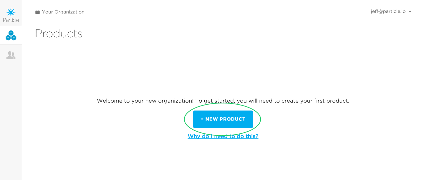
This will open up a modal where you can add basic details about your product:
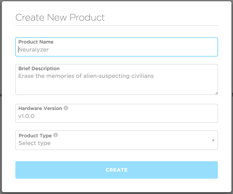
You now have your very first Particle product! Woot!
Adding team members
Now that you have created a Product successfully, it's time to add your coworkers and friends that are collaborating with you on your IoT product. Adding a team member will give them full access to your Product's Console.
To do this, click on the team icon () on the sidebar of your Product Console. This will direct you to the team page, where you can view and manage team members. Right now, your username should be the only one listed as a member of the Product. To add a new team member, just click the Invite team member button pictured below:
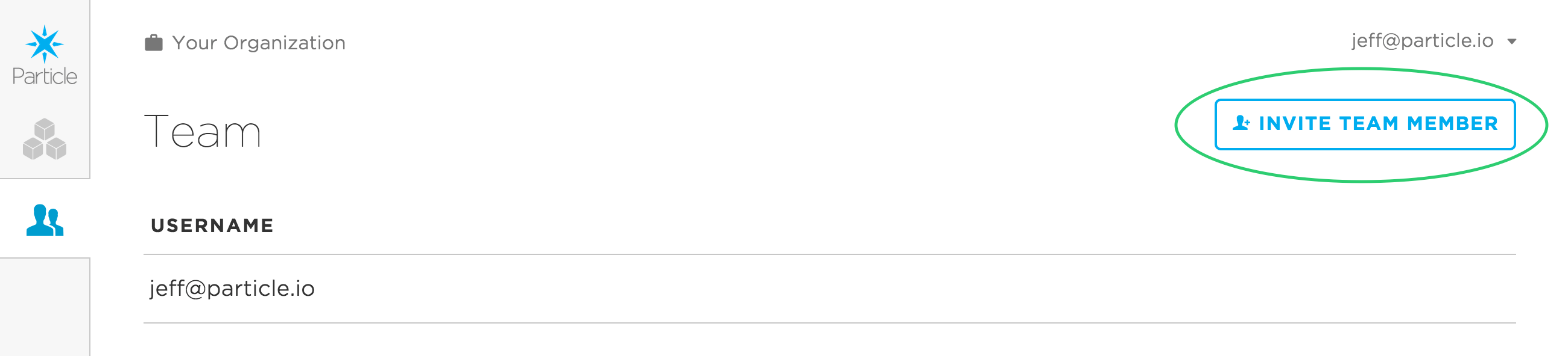
Clicking this button will open up a modal where you can invite a team member by email address. Before inviting a new team member, make sure that they already have a Particle account with the email address you will be using to invite them to the Product.
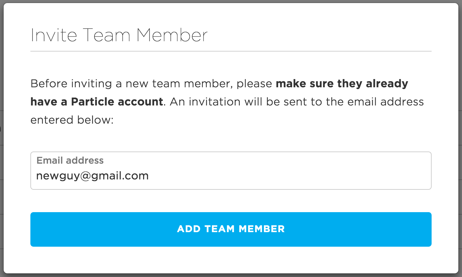
The invite team member modal
Once your team member is successfully invited, they will receive an email notifying them of their invitation. The next time they log into their Console, they will have the option of accepting or declining the invitation. Remember that you can have up to 5 team members in the free Prototype tier, so go send some invites!
API Users are also displayed in the team members tab.
Nice! Now you have a Product with a team.
API users
An API user account is a specific type of user account in the Particle platform that is designed to replace using 'human' accounts for programmatic tasks. It is highly recommended that you use this feature if you are connecting to the Particle cloud from an external web service.
In the Team tab for a product or organization, click the Add API user button.
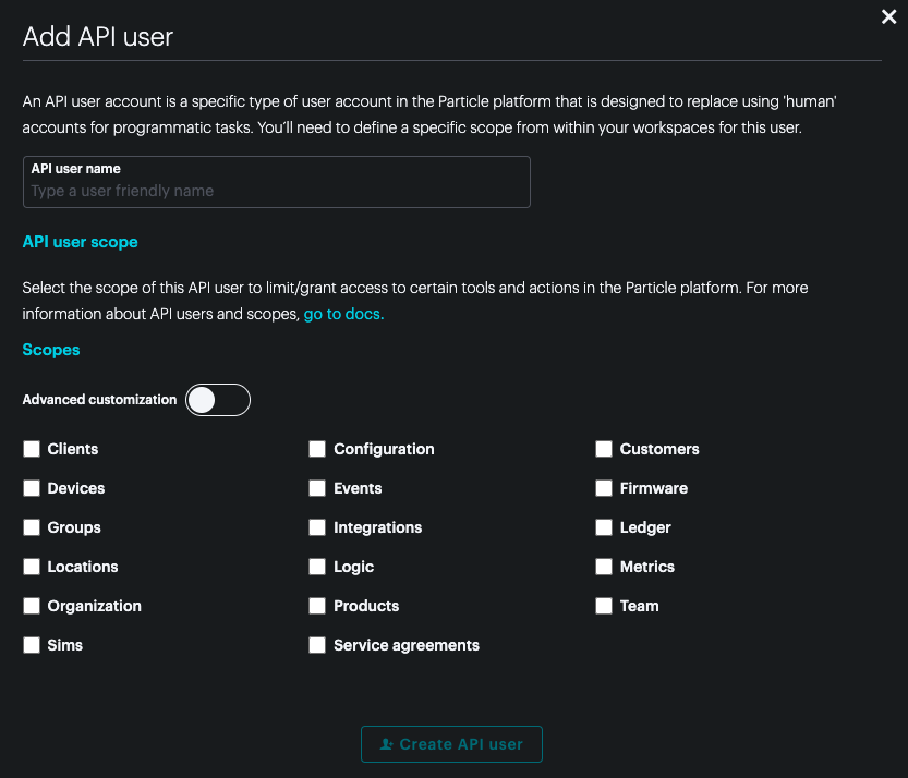
From this window you can select common scopes, or use the Advanced customization slider to access all of the available scopes.
Once you've created API users, they are listed below team members and can be edited or removed there.
Unlike most user tokens, API users tokens do not expire, since they are intended to be embedded in external services. For security reasons, you should still prevent accidentally exposing them, and also use the minimum set of scopes that are necessary.
Your product ID
When you created your product, a unique numeric ID was assigned to it. This small piece of information is very, very important to you as a product creator, and it will be used countless times during the development and manufacturing process for your product. You will be able to find your product's ID at any time in the navigation bar when viewing information about your product:

Your product ID is marked with a key icon
This ID will be used by the Particle Device Cloud to identify which devices belong to your Product, and subsequently it is part of what empowers you to manage firmware running on those devices en masse.
When working with devices that belong to your Product, it is important to note that this product ID must be compiled into the firmware that is running on each device. The product ID that the device reports to the cloud from its firmware will determine which Product it requests to become a part of. This will be covered more in-depth in the rollout firmware section below.
Adding devices
Now that you have your Product, it's time to import devices. Importing devices will assign them to your Product and allow you to start viewing and managing these devices within your Product Console.
For any product you may be developing, you likely have one or more Particle development kits (i.e. a Photon) that you have been using internally for prototyping purposes. We strongly recommend importing these devices into your Product, and using them as your development group.
In addition, you'll want to have a test group of devices to serve as the guinea pigs for new versions of product firmware. You should get into the habit of uploading a new version of firmware to your product, and flashing it to your test group to ensure your code is working as expected. This too will be covered more in-depth in the rollout firmware section below.
To import devices, click on the Devices icon in your product sidebar, then click on the "Import" button.
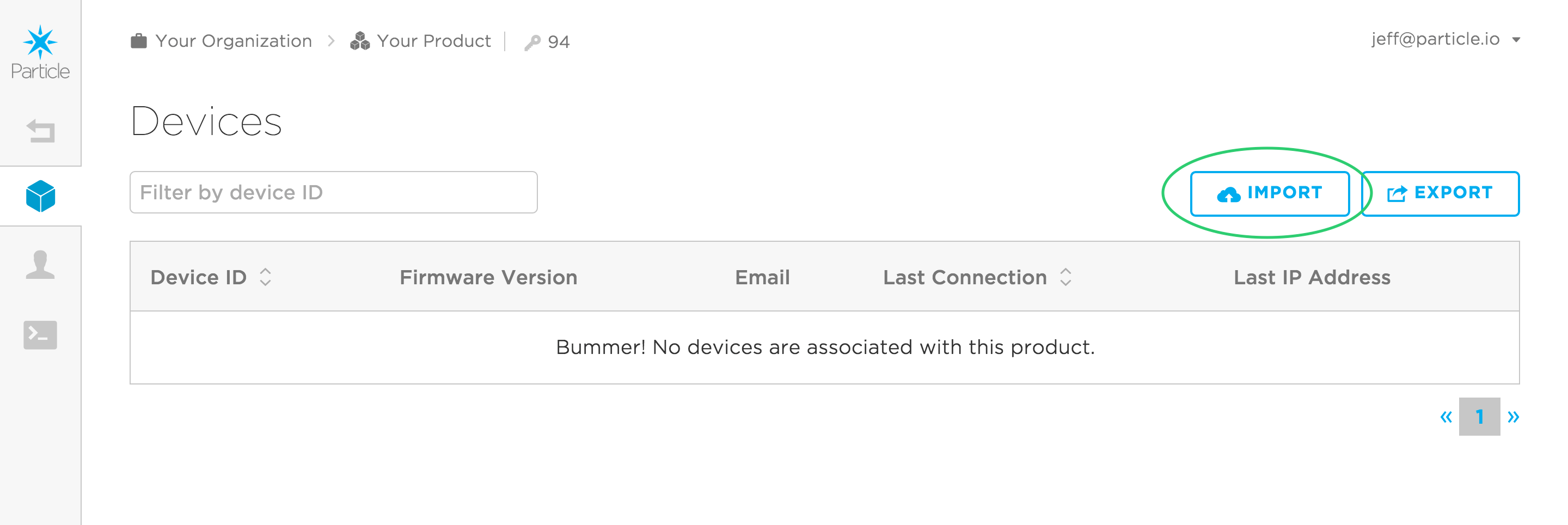
To allow you to import devices in bulk, we allow you to upload a file containing multiple device IDs. Create a .txt file that contains all of the IDs of devices that you would like to import into your product, one on each line. Not sure what your device ID is? You cannot register devices that have already been 'claimed' by someone outside of your team; all of these devices must either belong to a team member or belong to no one. The file should look something like this:
55ff6d04498b49XXXXXXXXXX
45f96d06492949XXXXXXXXXX
35ee6d064989a9XXXXXXXXXX
Where each line is one Device ID. Once you have your file ready, drop it onto the file selector in the import devices dialog box.
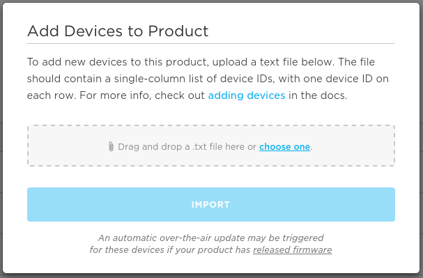
As noted at the bottom of the dialog box, if you previously rolled out firmware, those newly imported devices will be updated over the air to that firmware next time they connect to the Particle Device Cloud.
The Import Devices Tool can be used to simplify the process of doing multiple operations such as adding the device, claiming, naming, etc. for multiple devices.
Rollout firmware
One of the most valuable features of a Particle product is being able to seamlessly manage firmware on a fleet of IoT devices. You now have the ability to continuously improve how a device functions after deployment. In addition, product firmware management allows you to quickly and remotely fix bugs identified in the field, fleet-wide.
This happens through firmware releases, which targets some or all of a device fleet to automatically download and run a firmware binary.
Recommended development flow
When releasing firmware your fleet, it's helpful to first understand Particle's recommended release flow. This flow has been designed to minimize risk when deploying new firmware to devices:
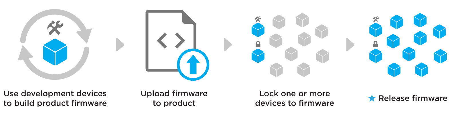
The recommended flow for releasing firmware
The first step of the release flow is using development devices to rapidly develop and iterate on product firmware. These are special product devices marked specifically for internal testing. This gives you the flexibility to experiment with new firmwares while still simulating behaviors of deployed devices in the production fleet. For information on marking a device as a development devices, check out the guide.
When you have finalized a firmware that you feel confident in releasing to your fleet, prepare the binary and upload it to your product.
Before releasing, you will need to ensure that the uploaded product firmware is running on at least one device in your product fleet. Your development device(s) may already be running the firmware, but we also recommend locking one or more devices to the newly updated firmware and ensure that it re-connects successfully to the cloud. This is because locking more closely represents a release action, with the specific firmware being delivered to a product device.
Mark the firmware as released. This will target product devices to automatically download and run the firmware. The Particle Device Cloud will respect the precedence rules to determine which firmware is delivered to a given device. You can also use device groups, to more safely roll out the firmware by targeting a subset of the fleet for release.
The rest of this section contains details around how to go through this process.
Development devices
Please visit the guide on development devices for information on this feature.
Preparing a binary
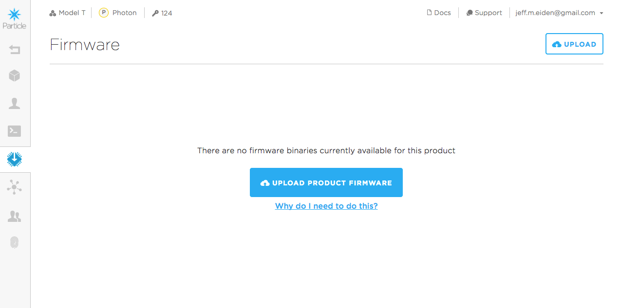
Click the Firmware icon in the left sidebar to get started. This will direct you to your product's firmware page, your centralized hub for viewing and managing firmware for your product's devices. If you haven't yet uploaded any firmware for this Product, your page will look like this:
If you have been using the Web IDE to develop firmware, you are used to the process of writing, compiling, and then flashing firmware. You will follow the same high-level process here, but altered slightly to work with a fleet of devices. The first thing you'll need to do is compile a firmware binary that you will upload to your Console.
Preparing firmware (4.x and later)
Unlike compiling a binary for a single device, it is critical that the firmware version is included in the compiled binary when targeting Device OS 4.0 or later.
Add the PRODUCT_VERSION macro to your main application .ino
file, below #include "Particle.h" if it includes that line. For more information, see PRODUCT_VERSION.
The firmware version must be an integer that increments each time a new binary is uploaded to the Console. This allows the Particle Device Cloud to determine which devices should be running which firmware versions.
Here is an example of Blinky with the correct product version details:
#include "Particle.h"

PRODUCT_VERSION(1);

int led = D0;  // You'll need to wire an LED to this one to see it blink.

void setup() {
  pinMode(led, OUTPUT);
}

void loop() {
  digitalWrite(led, HIGH);   // Turn ON the LED pins
  delay(300);               // Wait for 1000mS = 1 second
  digitalWrite(led, LOW);    // Turn OFF the LED pins
  delay(300);               // Wait for 1 second in off mode
}
Preparing firmware (3.x and earlier)
Unlike compiling a binary for a single device, it is critical that the product ID and a firmware version are included in the compiled binary. Specifically, you must add PRODUCT_ID([your product ID]) and PRODUCT_VERSION([version]) into the application code of your firmware. For more information, see PRODUCT_VERSION.
Add these two macros near the top of your main application .ino
file, below #include "Particle.h" if it includes that line. Remember
that your product ID can be found in the navigation
of your Console. The firmware version must be an integer that increments
each time a new binary is uploaded to the Console. This allows the
Particle Device Cloud to determine which devices should be running which firmwares.
Here is an example of Blinky with the correct product and version details:
PRODUCT_ID(94);
PRODUCT_VERSION(1);

int led = D0;  // You'll need to wire an LED to this one to see it blink.

void setup() {
  pinMode(led, OUTPUT);
}

void loop() {
  digitalWrite(led, HIGH);   // Turn ON the LED pins
  delay(300);               // Wait for 1000mS = 1 second
  digitalWrite(led, LOW);    // Turn OFF the LED pins
  delay(300);               // Wait for 1 second in off mode
}
Compiling binaries
If you are using Particle Workbench, follow the instructions to use the Particle: Cloud Compile or Particle: Compile Application (local) to create a firmware binary.
If you are in the Web IDE, you can easily download a compiled binary by clicking the code icon () in your sidebar. You will see the name of your app in the pane, along with a download icon (shown below). Click the download icon to compile and download your current binary.
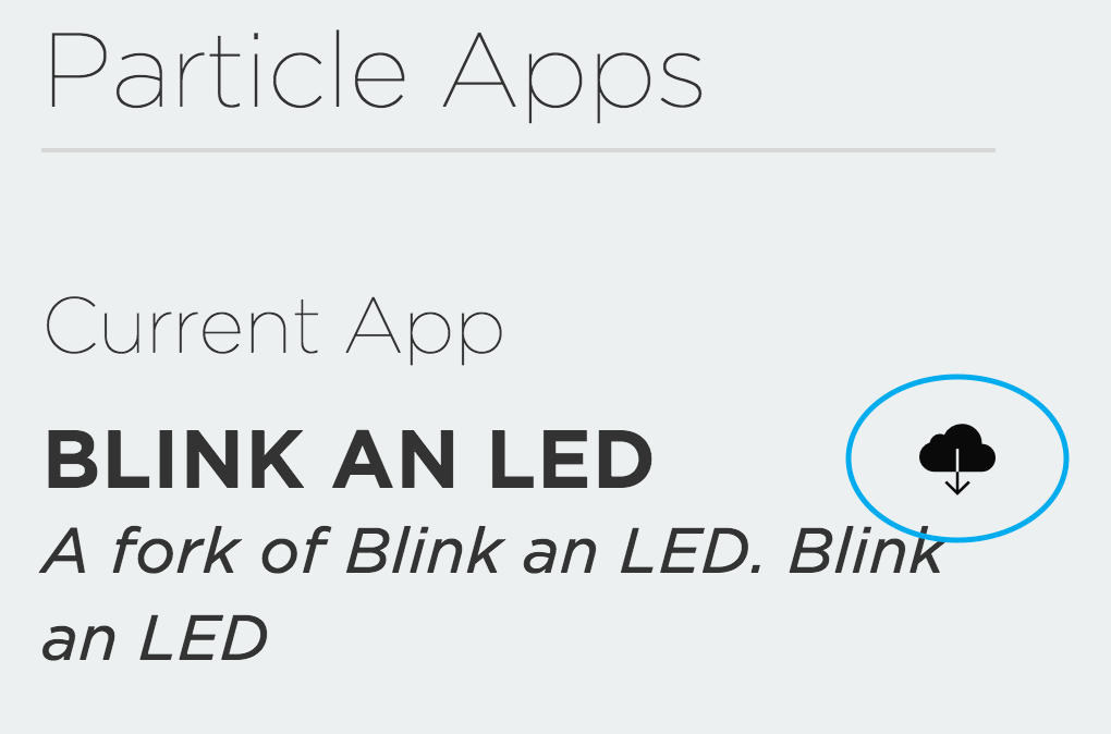
Compile and download a product binary from the web IDE
Once you have a binary ready to go, it's time to upload it to the Console!
Uploading firmware
Back on the firmware page, click on the Upload button in the top-right corner of the page. This will launch the upload firmware modal:
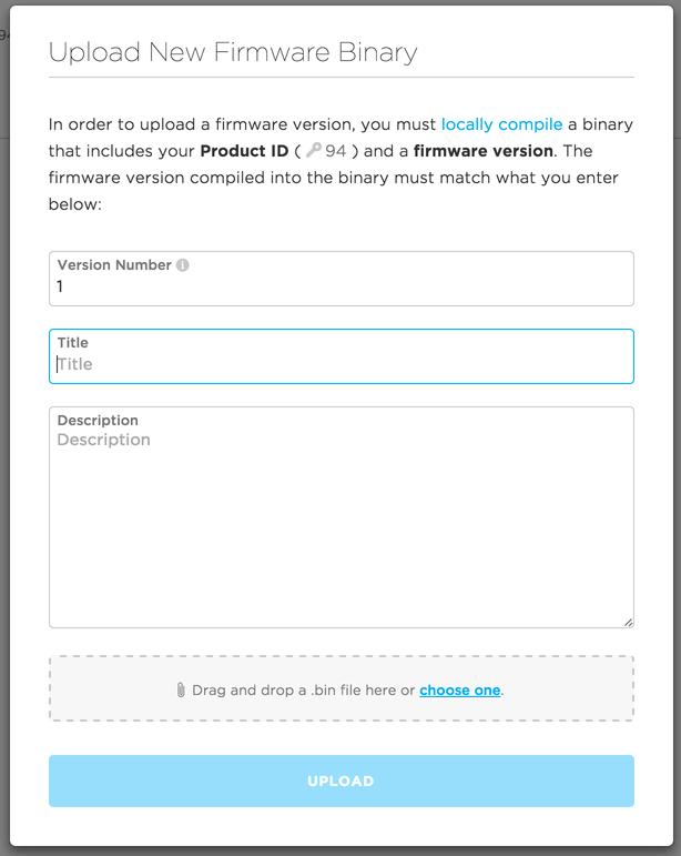
A few things to keep in mind here:
- The firmware version that you enter into this screen must match what you just compiled into your binary. Madness will ensue otherwise!
- You should give your firmware a distinct title that concisely describes how it differs from other versions of firmware. This name will be important in how firmware is rolled out to devices
- Attach your newly compiled
.binfile in the gray box
Click upload. Congrats! You've uploaded your first version of product firmware! You should now see it appear in your list of firmware versions.
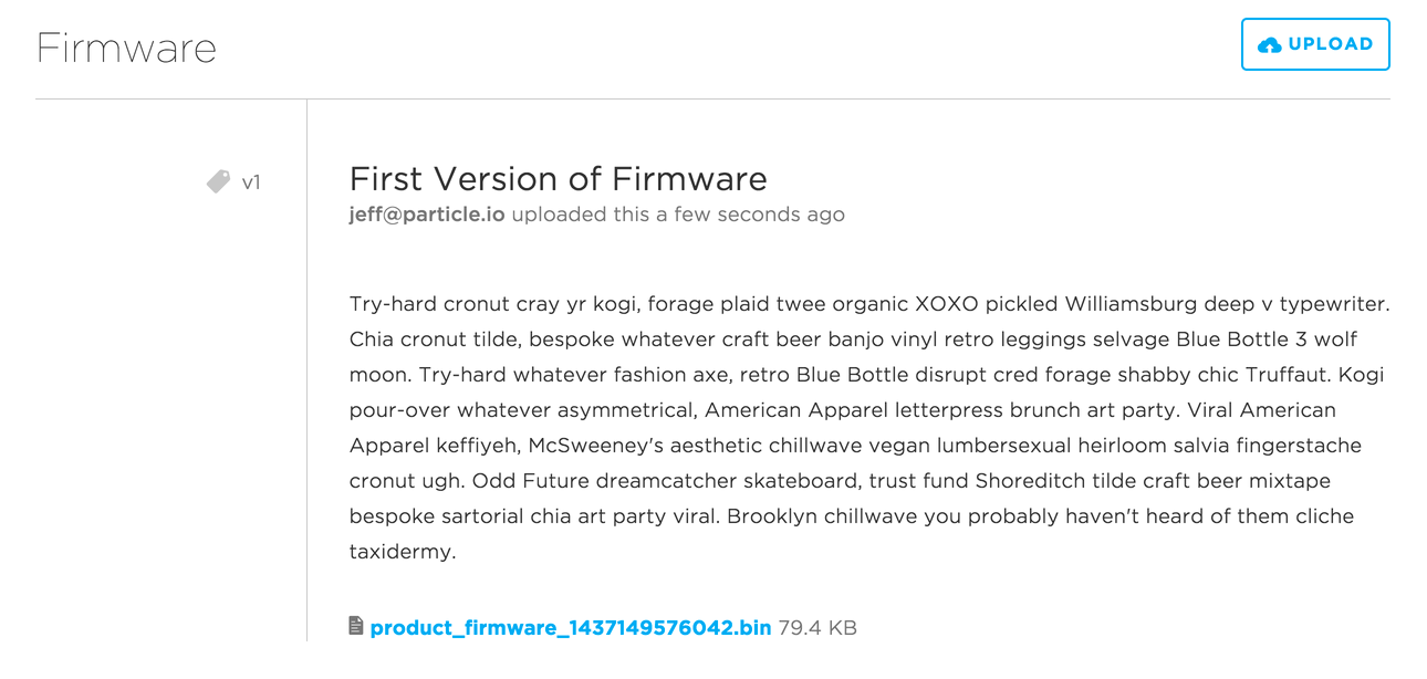
Your firmware version now appears in your list of available binaries
You can update the details of your product firmware version by clicking Edit when hovering over that firmware version.
If you find a problem with your firmware version during testing, you can delete the firmware version, recompile it and reupload it. It is only possible to delete a firmware version before marking it as released.
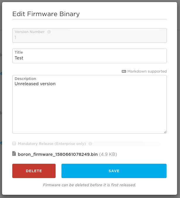
Edit the details of your firmware version or delete an unreleased version
Releasing firmware
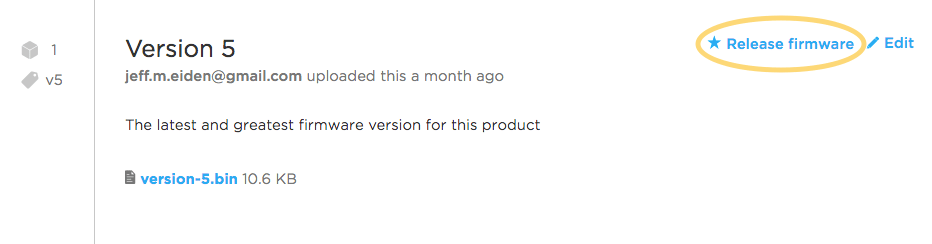
Time to flash that shiny new binary to some devices! Notice that when you hover over a version of firmware, you have the ability to release firmware. Releasing firmware is the mechanism by which any number of devices can receive a single version of firmware without being individually targeted.
Imagine identifying a bug in your firmware and pushing out a fix to thousands of devices that are out in the field. Or, consider the possibility of continuing to add new capabilities to your fleet connected devices, even after being deployed. It is all possible via releasing firmware.
As a product creator, you can choose to release firmware to some or all of your product fleet. Releasing a firmware as the product default sets the firmware as the default version available to all devices in the fleet to download and run.
To start the release process, place your cursor over the firmware you want to release and click Release firmware:
A modal will appear, asking you to confirm the action you are about to take:
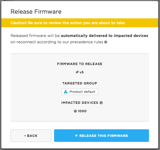
Always confirm the version, targeted group(s) and impacted devices before releasing firmware to your device fleet to ensure you are taking the desired action.
Impacted devices refers specifically to the number of devices that will receive an OTA firmware update as a direct result of this action. Keep in mind that releasing firmware always presents risk. Anytime the code on a device is changed, there is a chance of introducing bugs or regressions. As a safeguard, a firmware version must be successfully running on at least one device before it can be released.
When you have confirmed the release is what you have intended, click the Release this firmware button. Note that the devices will not receive the firmware immediately; instead, they will be targeted for an over-the-air update the next time they start a new secure session with the cloud (this is called a handshake).
It is also possible to release firmware to a subset of your product fleet, using device groups. For more information on fine-grained firmware management, please check out the guide on device groups.
Locking firmware
In many cases, you may want to force a device to download and run a specific version of product firmware. This is referred to as locking the device. You can lock a device to a new version of product firmware to test it before releasing the firmware to the fleet.
To lock a device to a firmware, find the device on your product's devices view. Click on the device, which will take you to the device details view. Click on the Edit button:
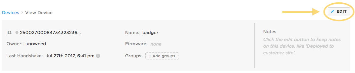
This will allow you to edit many aspects of the device's state, including the firmware it is targeted to run. Find the Firmware section, select a version of firmware you want to lock the device to, and click the Lock button as sown below:
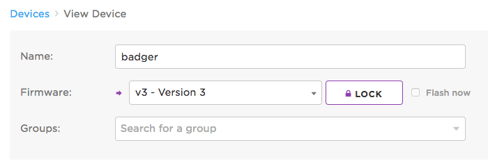
If the device is currently online, you can optionally immediately trigger an OTA update to the device by checking Flash now next to the lock button. Otherwise, the device will download and run the locked firmware the next time it handshakes with the cloud (starts a new secure session, most often on reset).
Once the device downloads and runs the locked firmware, it will no longer be targeted by the Particle cloud for automatic firmware updates, until it is unlocked. For more details, please read the firmware precedence rules.
Unlocking firmware
Unlocking a product device breaks its association with the locked firmware version and makes the device eligible to receive released product firmwares once again.
To unlock a device, visit the device's details view by clicking on it from your product's device list. Click the Edit button (shown above), and then click the Unlock button:
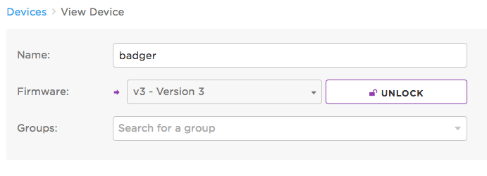
The device above is now unlocked from version 3 of product firmware, and may be targeted to receive a released firmware next time it handshakes with the cloud.
Firmware precedence rules
Devices in your fleet will be targeted to receive a version of product firmware according to these precedence rules:
A device that has been individually locked to a version of product firmware is respected above all else, and will not be overwritten by any released firmwares.
If unlocked, devices belonging to a group will receive the corresponding group's released firmware (if a firmware has been released to the group). When a device belongs to multiple groups that each have released firmware, the highest firmware version will be preferred
If a device is unlocked and does not belong to any groups with released firmware, it will receive the Product default released firmware (if a firmware has been released as the Product default)
If none of the above conditions result in a device being targeted for a product firmware, it will not receive an automatic OTA update from the Particle cloud
Managing customers
Customers are generally unnecessary unless you are using the Device Setup SDK for the P1 and Photon. We recommend not using customers unless absolutely necessary as it will add considerable complexity. The Device Setup SDK cannot be used with the P2, Photon 2, or Argon.


Monitoring event logs
The Logs page () is also available to product creators! Featuring the same interface as what you are used to with the developer version of the Console, the logs will now include events from any device identifying as your product. Use this page to get a real-time look into what is happening with your devices. In order to take full advantage of the Logs page, be sure to use Particle.publish() in your firmware.
Prior to March 2023, webhook events like hook-sent, hook-error, and hook-response only went to the device owner's event stream. If the device was unclaimed, the events disappeared. Now, these events also appear in the product event stream, in the console, SSE event stream, and webhooks.
Managing your billing
To see all billing related information, you can click on the billing icon in the sidebar (). This is the hub for all billing-related information and actions. For more specifics about the pricing plans and frequently asked questions, go check out the Pricing page.
How billing works
Free plan
- Up to 100 devices, any mix of cellular and Wi-Fi
- 100K Data Operations (100,000) per month, for both cellular and Wi-Fi, pooled across all devices
- Up to 100 MB of cellular data per month, pooled across all devices, at no charge
- No credit card required
- Device communication is paused1 when the monthly limit is reached
For more information see Device Cloud - Introduction - Pricing.
1 You will receive warnings by email, and as a pop-up and in the Billing & Usage tab in the console at 70%, 90%, and 100% of the allowable data operations. Once you reach the 100% limit you have three days to switch the the Basic plan, or data will be stopped until the end of your billing month. It will automatically resume on the free plan at the beginning of the next billing month, still on the free plan, if you do not upgrade.
Free plan products
Products can be prototyped in the Free plan at no charge. However, there is a limit of 100 devices for Free plan products.
Basic plan
- A block includes 720K Data Operations (720,000) per month and up to 100 devices
- Add as many blocks as you need for more Data Operations or more devices
- No limit to the number of blocks you can purchase self-service
- Up to 540 MB of cellular data per month, pooled across all devices, for each block purchased
In the Basic plan, usage is measured by blocks. You can choose how many blocks you initially want to purchase in advance. It is also possible to add blocks if you run out of Data Operations, available devices, or cellular data.
You will receive warnings by email, and as a pop-up and in the Billing & Usage tab in the console at 70%, 90%, and 100% of the allowable data operations for your current number of blocks. Once you reach the 100% limit, an additional block will be added to your plan. Starting at the next billing month your plan will include these additional block(s) and you will be billed accordingly. There is no additional charge at the time of the overage; it occurs only on the next billing cycle.
In the Basic and Enterprise plans, you will also have access to an Organization, which allows finer access control to multiple products.
The number of devices is limited by the number of blocks you have purchased, 100 devices per block. You can purchase as many blocks as necessary to support number of devices you need.
Status
It’s easy to find out the status of your Product’s metrics. Visit console.particle.io/billing and you’ll see an up-to-date list of each Product you own, how many outbound events they’ve used that billing cycle, number of devices in each, and how many team members they have. The renewal date for each Product plan is also shown, so you know when the next bill is coming up.
Updating your credit card
You can update your credit card from the billing page by clicking on the "UPDATE" button next to the credit card on file. Whenever your credit card on file expires or no longer is valid, be sure to update your credit card info here to avoid any disruptions in your service.
Failed payments
If we attempt to charge your credit card and it fails, we do not immediately prevent you or your team from accessing your Device Management Console. We will continue to retry charging your card once every few days for a maximum of 3 retries. You will receive an email notification each time an attempt is made and fails. When you receive this notification, the best thing to avoid any interruption in service is to update your credit card.
Organizations
An organization makes it easy to manage multiple products with shared team members and billing. Organizations are available in the Basic and Enterprise plans.
If your account is a member of an organization, the Sandbox popup in the upper left corner of the Particle console lists the organizations you can select:
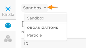
Selecting an organization brings up the organization view, which typically has:
- Products - the products in this organization.
- Team - the users in this organization and their roles (administrators, developers, etc.).
- Billing & Usage - only for users who have an Administrator role.
You still have granular access control at the product level when using an organization. For example, if you have a contractor who is working on a single product you can grant developer access to that product only instead of all products in your organization.
Asset Tracker features
All Asset Tracker devices are intended to be used in a product, not as developer devices. This makes it easy to manage a fleet of asset trackers, allowing per-fleet and per-device configuration settings, and features like fleet mapping. The Product Features in the previous section also apply to Tracker devices.
Map
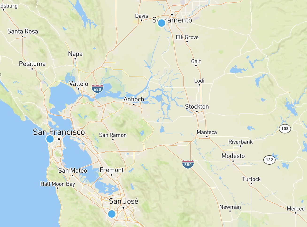
The map view shows your fleet of devices or selected devices on a map. The Map view is available for Asset Tracker products in the Maps icon.
![]()
You can show a subset of your devices on the map by searching:
- By Device ID
- By Device Name
- By Device Groups
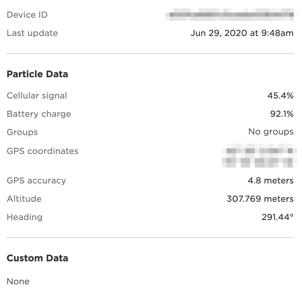
Each device has an overview available.
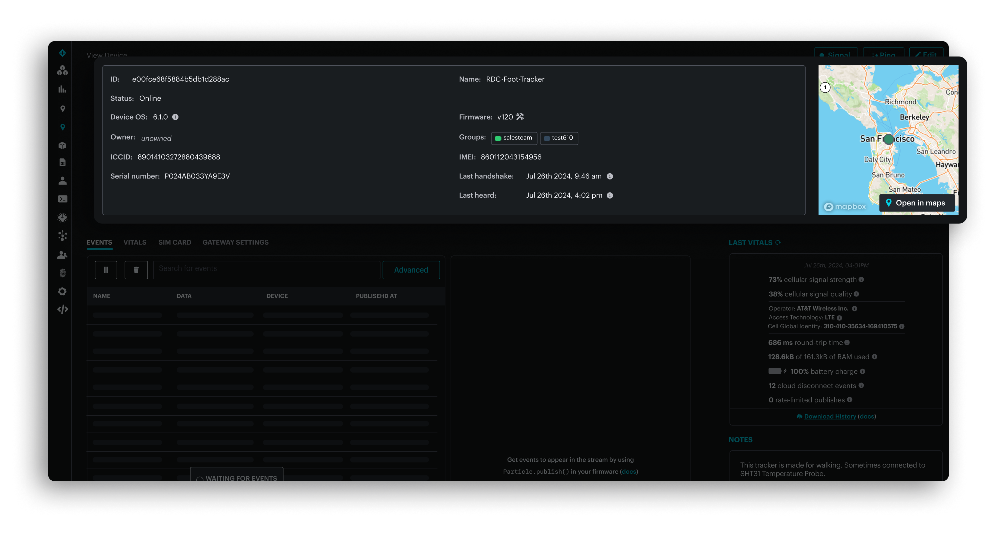
And view details about a specific device:
On the Tracker One the temperature ("temp") is shown in degrees Celsius. This is the temperature on the board, within the enclosure, and will typically be several degrees warmer than the ambient temperature.
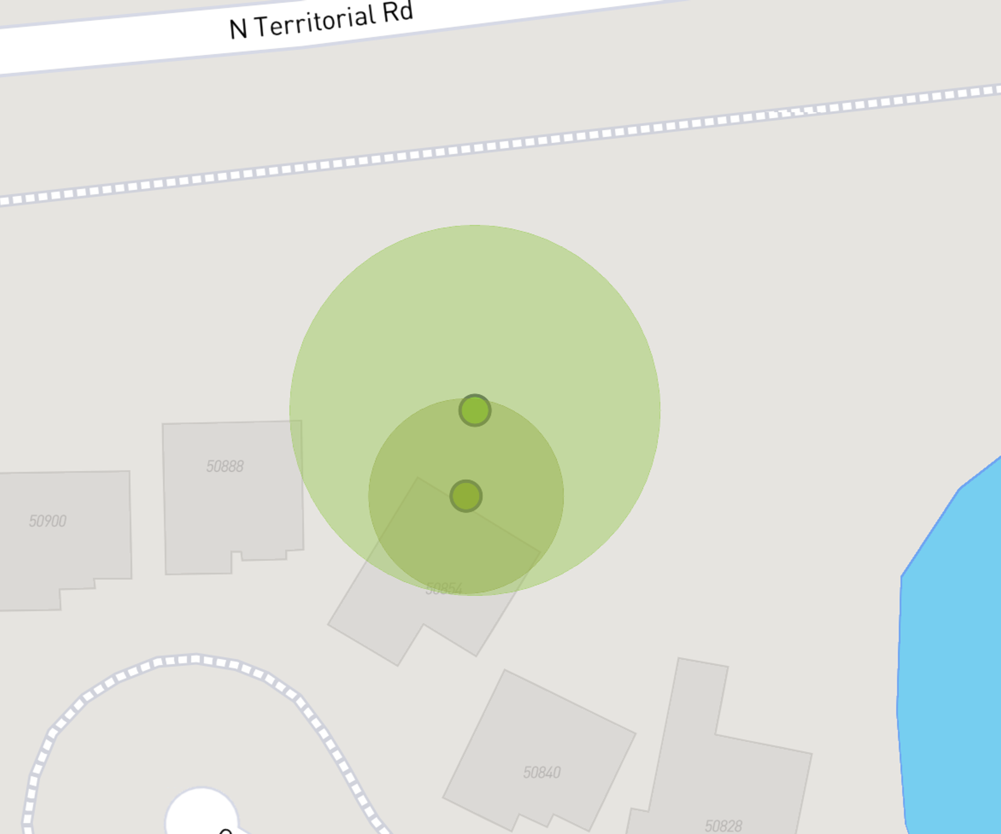
Accuracy circle
While GNSS is generally accurate, there can be uncertainty to the exact location when using cellular tower geolocation. There can also be uncertainty with Wi-Fi, and in some cases with GNSS if a a full set of satellites is not visible.
When zooming into the map, a circle indicates the radius of uncertainty; the device could be anywhere within the circle; it's exact location is not known.
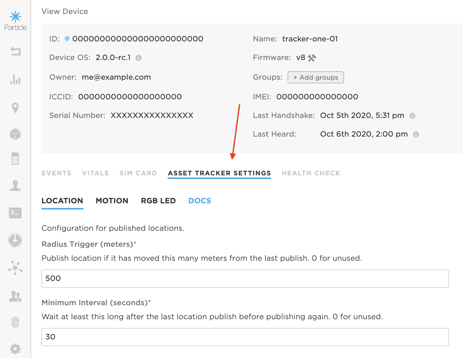
Device fleet settings
Your Tracker devices are intended to, in general, be configured with fleet-wide settings that are used for all devices in your fleet. The fleet-wide settings are in the Map View. Click Configure fleet button in the upper-left corner of the map to update Tracker Settings.
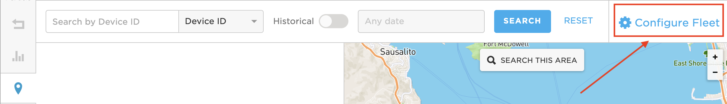
Note that the settings are automatically synchronized with the device, even if the device is asleep or disconnected at the time the change is made. When the device connects to the cloud again, the checksum of the current device and cloud settings are compared, and if they are different, an updated configuration is sent to the device.
Additionally, the Geofence settings are always per-device, with no fleet-wide default. It's also possible to have per-device configuration for your own custom settings. The per-device settings are within the device configuration, and do not appear in the fleet settings.
Finally, when a device is marked as a Development Device, all configuration fields can be configured per-device, and these can override the fleet settings. Development devices also do not get automatic fleet firmware updates.
Location settings
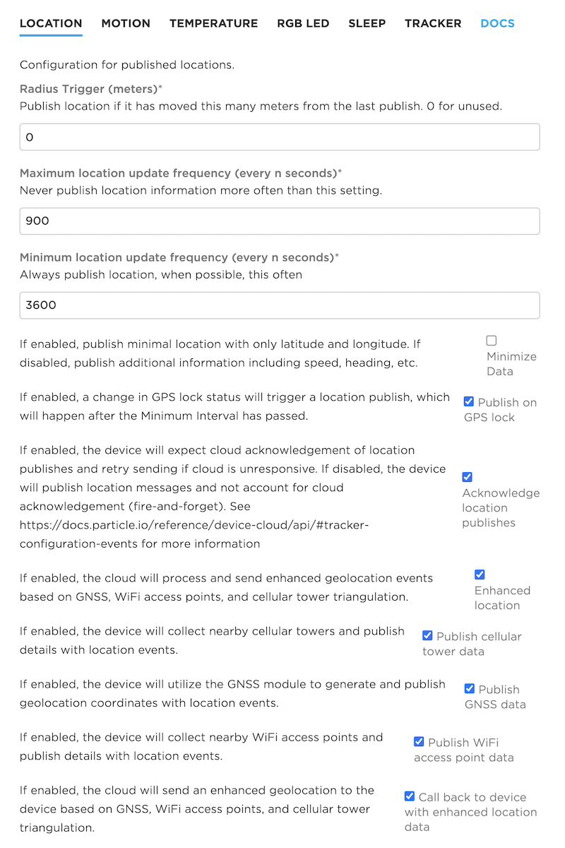
The Location settings include:
- Radius Trigger in meters, floating point. When the current position's distance from the last publish exceeds this distance, the new position is published. 0.0 means do not use a publish radius. The GNSS is not monitored during sleep mode, and the radius will only be checked when otherwise waking from sleep. The maximum location update frequency still limits how frequently publishes occur even if if the radius trigger is reached.
| US Units | Meters |
|---|---|
| 1 yard (3 feet) | 0.91 meters (approximately 1 meter) |
| 100 feet | 30.5 meters |
| 100 yards (length of American football field) | 91.4 meters |
| 1/4 mile | 402 meters |
| 1/2 mile | 805 meters |
| 1 mile | 1609 meters |
Maximum location update frequency in seconds. Wait at least this long in seconds after the last location publish before publishing again. 0 means do not limit. The maximum location update frequency prevents publishing too frequently, which can use excessive amounts of data.
When using sleep modes, this also controls how often to connect to the cellular network. A maximum location update frequency value of 10 minutes (600 seconds) or larger is recommended. Setting a very short maximum location update frequency with sleep mode can cause your SIM card to be banned for excessive reconnection to the cellular network by your mobile carrier.
Minimum location update frequency in seconds. Publish location this often (in seconds) even if there is no movement or other wake trigger. 0 means do not use an minimum update frequency; only publish location information when there is another trigger, such as movement. Including a minimum location update frequency of 8 hours (28800 seconds) or 24 hours (86400) can be helpful to make sure the device is still responding and report its battery level.
In some cases, you will want to set the maximum and minimum to the same value. This is common if you are not using a trigger like movement and instead always want to publish at a fixed frequency.
| Common Unit | Seconds |
|---|---|
| 1 minute | 60 |
| 5 minutes | 300 |
| 10 minutes | 600 |
| 15 minutes | 900 |
| 30 minutes | 1800 |
| 1 hour | 3600 |
| 2 hours | 7200 |
| 4 hours | 14400 |
| 8 hours | 28800 |
| 24 hours | 86400 |
Minimize Data. If checked, only only latitude and longitude data is sent on each location publish. If unchecked (the default), additional information such as speed and heading are sent.
Publish on GPS lock. If checked, publish location when GNSS lock is obtained, even if the device has not reached the radius trigger or maximum location update frequency yet. The minimum location update frequency is still obeyed.
Acknowledge location publishes. If checked, the device will expect cloud acknowledgement of location publishes and retry failed transmissions. If unchecked, one attempt will be made to send, which may or may not succeed. If you are publishing frequently, it may be preferable to lose some points, rather than record delayed information.
Enhanced location. If checked, the Particle cloud will process location fusion, enhanced geolocation using Wi-Fi access points and cellular tower information.
Publish cellular tower data. If checked, the Tracker will include information about nearby cellular towers with location events.
Publish GNSS data. If checked, the Tracker will use the GNSS (GPS) module for geolocation.
Publish Wi-Fi access point data. If checked, the Tracker will include nearby Wi-Fi access points in location publishes. The Wi-Fi access points are not connected to; most Wi-Fi access points periodically broadcast their presence to allow Wi-Fi devices to find them. This public information is used by the Wi-Fi geolocation service.
Callback to device with enhanced location data. If checked, the Particle cloud will send back enhanced geolocation data obtained from Wi-Fi or cellular tower information back to the device. This is useful if your device firmware wants to process this information on device. If you're only tracking location from the cloud, it's not necessary to enable this option.
Radius Trigger (meters) configuration
| Field | Value |
|---|---|
| Schema ID | #/properties/location/properties/radius |
| Title | Radius Trigger (meters) |
| Description | Publish location if it has moved this many meters from the last publish. 0 for unused. |
| Example values | 5 |
Maximum location update frequency (every n seconds) configuration
| Field | Value |
|---|---|
| Schema ID | #/properties/location/properties/interval_min |
| Title | Maximum location update frequency (every n seconds) |
| Description | Never publish location information more often than this setting. |
| Default Value | 900 |
| Example values | 1000 |
Minimum location update frequency (every n seconds) configuration
| Field | Value |
|---|---|
| Schema ID | #/properties/location/properties/interval_max |
| Title | Minimum location update frequency (every n seconds) |
| Description | Always publish location, when possible, this often |
| Default Value | 3600 |
| Example values | 7200 |
Minimize Data configuration
| Field | Value |
|---|---|
| Schema ID | #/properties/location/properties/min_publish |
| Title | Minimize Data |
| Description | If enabled, publish minimal location with only latitude and longitude. If disabled, publish additional information including speed, heading, etc. |
| Example values | true |
Publish on GPS lock configuration
| Field | Value |
|---|---|
| Schema ID | #/properties/location/properties/lock_trigger |
| Title | Publish on GPS lock |
| Description | If enabled, a change in GPS lock status will trigger a location publish, which will happen after the Minimum Interval has passed. |
| Default Value | true |
| Example values |
Acknowledge location publishes configuration
| Field | Value |
|---|---|
| Schema ID | #/properties/location/properties/loc_ack |
| Title | Acknowledge location publishes |
| Description | If enabled, the device will expect cloud acknowledgement of location publishes and retry sending if cloud is unresponsive. If disabled, the device will publish location messages and not account for cloud acknowledgement (fire-and-forget). See https://docs.particle.io/reference/device-cloud/api/#tracker-configuration-events for more information |
| Default Value | true |
| Example values | true |
Enhanced location configuration
| Field | Value |
|---|---|
| Schema ID | #/properties/location/properties/enhance_loc |
| Title | Enhanced location |
| Description | If enabled, the cloud will process and send enhanced geolocation events based on GNSS, WiFi access points, and cellular tower triangulation. |
| Default Value | true |
| Example values | true |
Publish cellular tower data configuration
| Field | Value |
|---|---|
| Schema ID | #/properties/location/properties/tower |
| Title | Publish cellular tower data |
| Description | If enabled, the device will collect nearby cellular towers and publish details with location events. |
| Default Value | true |
| Example values | true |
Publish GNSS data configuration
| Field | Value |
|---|---|
| Schema ID | #/properties/location/properties/gnss |
| Title | Publish GNSS data |
| Description | If enabled, the device will utilize the GNSS module to generate and publish geolocation coordinates with location events. |
| Default Value | true |
| Example values | true |
Publish WiFi access point data configuration
| Field | Value |
|---|---|
| Schema ID | #/properties/location/properties/wps |
| Title | Publish WiFi access point data |
| Description | If enabled, the device will collect nearby WiFi access points and publish details with location events. |
| Default Value | true |
| Example values | true |
Call back to device with enhanced location data configuration
| Field | Value |
|---|---|
| Schema ID | #/properties/location/properties/loc_cb |
| Title | Call back to device with enhanced location data |
| Description | If enabled, the cloud will send an enhanced geolocation to the device based on GNSS, WiFi access points, and cellular tower triangulation. |
| Example values | true |
Publish extra information to assist with debugging GNSS configuration
| Field | Value |
|---|---|
| Schema ID | #/properties/location/properties/diag |
| Title | Publish extra information to assist with debugging GNSS |
| Description | If enabled, publish GNSS constellation counts and C/NO characteristics. |
| Example values | true |
Store and forward
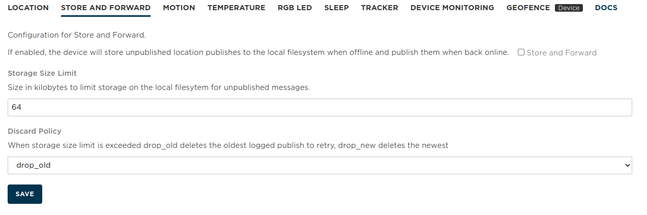
In Tracker Edge v18 and later, it's possible to enable store and forward mode from this panel. If the device is offline, such as from poor cellular connectivity, location publishes are saved to the device flash file system and published when connectivity is restored.
When disabled, location publishes that occur when the device does not have cellular connectivity are discarded. This makes sense if you only want to know where the device is currently, not where it has been in the past.
Store and forward is enabled when the checkbox is checked.
Storage Size Limit in kilobytes. Default: 64K. While the flash file system is 4 MB, you should not use the entire file system for store and forward. Also, since publishes occur one per second when reconnecting, sending large amount of historical location data will use a lot of data operations and time.
Discard Policy is drop_old or drop_new which determines whether to discard the oldest or newest location data when the storage size reaches the limit.
Store and Forward configuration
| Field | Value |
|---|---|
| Schema ID | #/properties/store/properties/enable |
| Title | Store and Forward |
| Description | If enabled, the device will store unpublished location publishes to the local filesystem when offline and publish them when back online. |
| Default Value | true |
| Example values | true |
Storage Size Limit configuration
| Field | Value |
|---|---|
| Schema ID | #/properties/store/properties/quota |
| Title | Storage Size Limit |
| Description | Size in kilobytes to limit storage on the local filesytem for unpublished messages. |
| Default Value | 64 |
Discard Policy configuration
| Field | Value |
|---|---|
| Schema ID | #/properties/store/properties/policy |
| Title | Discard Policy |
| Description | When storage size limit is exceeded drop_old deletes the oldest logged publish to retry, drop_new deletes the newest |
| Default Value | drop_old |
| Enumeration values | drop_old, drop_new |
Motion settings
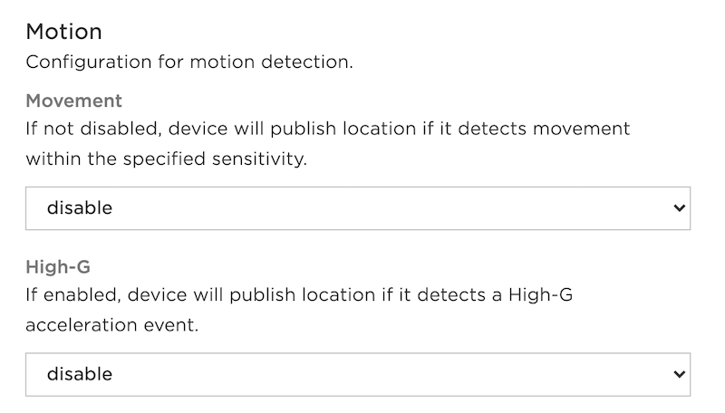
The motion settings determine how the IMU (inertial measurement unit, the accelerometer) is used to determine whether to publish a location. The Interval minimum also applies to motion events. Movement events can occur while the device is awake, also also wake a device from sleep mode.
Movement publishes if the device moves, and has several sensitivity options:
- Disable: Do not use motion detection (the default).
- Low: Least sensitive, large motion is required to publish.
- Medium
- High: Most sensitive, even a small amount of motion will trigger publish.
High G publishes if there is a High-G acceleration event, such as the device falling. This is 4g for at least 2.5ms.
- Disable: High-G events are not generated (the default).
- Enable: High-G events are generated.
Movement Sensitivity configuration
| Field | Value |
|---|---|
| Schema ID | #/properties/imu_trig/properties/motion |
| Title | Movement Sensitivity |
| Description | If not disabled, device will publish location if it detects movement. Low sensitivity requires a large motion to publish. |
| Default Value | disable |
| Enumeration values | disable, low, medium, high |
High-G configuration
| Field | Value |
|---|---|
| Schema ID | #/properties/imu_trig/properties/accel |
| Title | High-G |
| Description | If enabled, device will publish location if it detects a High-G acceleration event. |
| Default Value | disable |
| Enumeration values | disable, enable |
RGB LED Settings
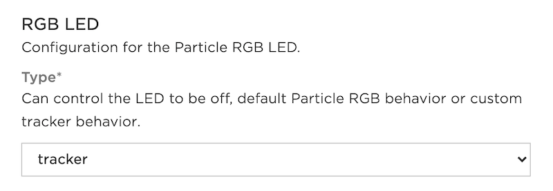
The Tracker Firmware configures the RGB status LED.
The Type popup menu has the following options:
- off: The RGB LED is turned off (dark).
- tracker: Color indicates signal strength (yellow = lower signal strength, green = higher signal strength). Fast breathing red while connecting to cellular.
- particle: Use standard Particle colors like breathing cyan instead of tracker-style colors. Default for Tracker SoM Evaluation Board.
Type configuration
| Field | Value |
|---|---|
| Schema ID | #/properties/rgb/properties/type |
| Title | Type |
| Description | Can control the LED to be off, default Particle RGB behavior or custom tracker behavior. |
| Default Value | particle |
| Enumeration values | off, particle, tracker |
Sleep settings
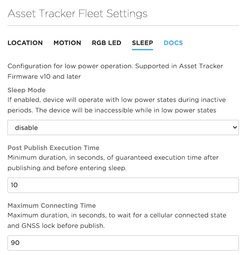
Sleep mode allows the device to enter a low-power state when idle, conserving battery power. Sleep requires Tracker Edge v10 and Device OS 2.0.0-rc.3 or later. There are additional details in the Tracker Sleep page.
Sleep Mode can be set to enable or disable.
Post Publish Execution Time is the minimum duration in seconds to stay awake after publishing before going to sleep. The default is 10 seconds. This provides enough time to make sure a software update can be started when waking up from sleep.
Maximum Connecting Time is the maximum duration, in seconds, to wait for being cellular-connected and to obtain a GNSS lock before publishing. If connecting takes too long, then the device will go back to sleep instead of continuously attempting to connect. The default is 90 seconds.
You can find out more in the Tracker Sleep Tutorial.
Sleep Mode configuration
| Field | Value |
|---|---|
| Schema ID | #/properties/sleep/properties/mode |
| Title | Sleep Mode |
| Description | If enabled, device will operate with low power states during inactive periods. The device will be inaccessible while in low power states |
| Default Value | disable |
| Enumeration values | disable, enable |
Post Publish Execution Time configuration
| Field | Value |
|---|---|
| Schema ID | #/properties/sleep/properties/exe_min |
| Title | Post Publish Execution Time |
| Description | Minimum duration, in seconds, of guaranteed execution time after publishing and before entering sleep. |
| Default Value | 10 |
| Example values | 10 |
Maximum Connecting Time configuration
| Field | Value |
|---|---|
| Schema ID | #/properties/sleep/properties/conn_max |
| Title | Maximum Connecting Time |
| Description | Maximum duration, in seconds, to wait for a cellular connected state and GNSS lock before publish. |
| Default Value | 90 |
| Example values | 120 |
Device monitoring
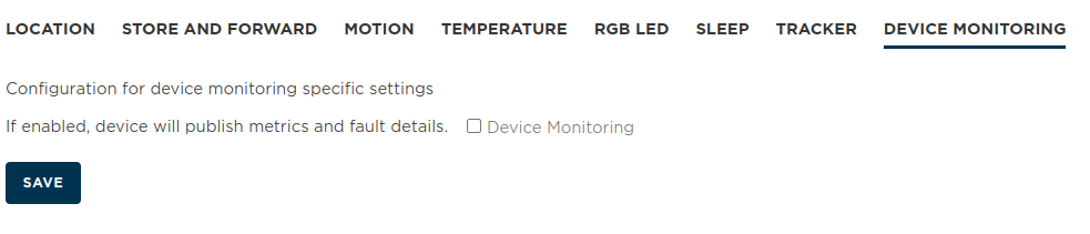
Device Monitoring publishes additional metrics and also fault (crash log) information. This can help troubleshoot problems, however it will use additional data operations.
See the Memfault Integration for more information.
Device Monitoring configuration
| Field | Value |
|---|---|
| Schema ID | #/properties/monitoring/device_monitor |
| Title | Device Monitoring |
| Description | If enabled, device will publish metrics and fault details. |
| Example values |
Temperature trigger
High temperature threshold (Celsius) configuration
| Field | Value |
|---|---|
| Schema ID | #/properties/temp_trig/high |
| Title | High temperature threshold (Celsius) |
| Description | Publish location once if temperature is greater than or equal to threshold. The temperature will be required to be less than the high threshold minus hysteresis to clear event, when latching, or publish again when latching disabled. Hysteresis must be valid. |
| Default Value | 150 |
| Example values | 65 |
High temperature monitoring configuration
| Field | Value |
|---|---|
| Schema ID | #/properties/temp_trig/high_en |
| Title | High temperature monitoring |
| Description | If enabled, compare current temperature against high threshold. |
| Example values | true |
High temperature event latching. configuration
| Field | Value |
|---|---|
| Schema ID | #/properties/temp_trig/high_latch |
| Title | High temperature event latching. |
| Description | Enable latching of high temperature trigger event until temperature has fallen below hysteresis level; otherwise, generate one high temperature event. |
| Example values | true |
Low temperature threshold (Celsius) configuration
| Field | Value |
|---|---|
| Schema ID | #/properties/temp_trig/low |
| Title | Low temperature threshold (Celsius) |
| Description | Publish location once if temperature is less than or equal to threshold. The temperature will be required to be more than the low threshold plus hysteresis to clear event, when latching, or publish again when latching disabled. Hysteresis must be valid. |
| Default Value | -40 |
| Example values |
Low temperature monitoring. configuration
| Field | Value |
|---|---|
| Schema ID | #/properties/temp_trig/low_en |
| Title | Low temperature monitoring. |
| Description | If enabled, compare current temperature against low threshold. |
| Example values | true |
Low temperature event latching. configuration
| Field | Value |
|---|---|
| Schema ID | #/properties/temp_trig/low_latch |
| Title | Low temperature event latching. |
| Description | Enable latching of low temperature trigger event until temperature has risen above hysteresis level; otherwise, generate one low temperature event. |
| Example values | true |
Hysteresis temperature threshold (Celsius) configuration
| Field | Value |
|---|---|
| Schema ID | #/properties/temp_trig/hyst |
| Title | Hysteresis temperature threshold (Celsius) |
| Description | Hysteresis threshold applied to high and low thresholds to allow further temperature publishes. 0.0 for unused. |
| Example values | 10 |
Tracker settings
Device Monitoring configuration
| Field | Value |
|---|---|
| Schema ID | #/properties/monitoring/device_monitor |
| Title | Device Monitoring |
| Description | If enabled, device will publish metrics and fault details. |
| Example values |
Device settings
Geofence settings are only configurable per-device, not in the fleet settings.
Normally, for other settings, you will use the product settings across your fleet of Tracker devices. If you mark a device as a Development Device, you can change settings on a per-device basis within the Device Configuration.
Geofence settings
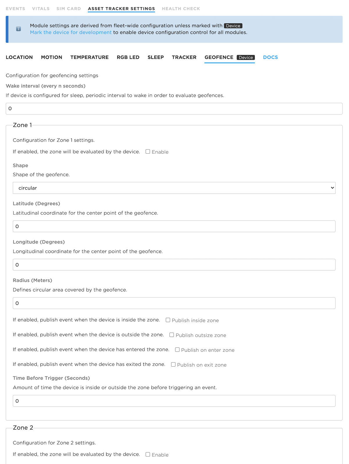
Wake interval configures how often to wake to check whether the device is inside or outside of the geofence. If no notification is required, and the Minimum location update frequency has not been met yet, then the device may go back to sleep quickly without having to connect to cellular. If zero, the geofence will only be checked when otherwise waking from sleep. If you are not using sleep modes, the wake interval is ignored.
There are up to four notification zones, each of which can have their own settings.
Enable turns on or off a zone, allowing it to be easily disabled.
Shape sets the shape. Only one shape, Circular, is supported at this time.
Latitude (Degrees) is the latitude of the center of the circle. This must be a decimal number (not hours, minutes, seconds), -90.0 to 90.0.
Longitude (Degrees) is the latitude of the center of the circle. This must be a decimal number (not hours, minutes, seconds), -180.0 to 180.0.
Radius (Meters) is the radius of the circle in meters (decimal).
Publish inside zone publishes when inside the circle, limited by the Maximum location update frequency.
Publish outside zone publishes when outside the circle, limited by the Maximum location update frequency.
Publish on enter zone publishes when the device moves into the circle.
Publish on exit zone publishes when the device moves out of the circle.
Time Before Trigger requires that the device be inside or outside of the zone for this many seconds before notification. This can help reduce false alarms when the device may be near the edge of the zone. 0 means notify immediately without waiting. This is an integer.
The publish on inside, outside, enter, and exit affect the trig array in the location event. The following values may be present in the trig array for geofence events. Multiple items may be present:
outside1The device is currently outside of geofence zone 1 (and outside trigger is enabled)inside1The device is currently inside of geofence zone 1 (and inside trigger is enabled)enter1The device has entered geofence zone 1 (and enter trigger is enabled)exit1The device has exited geofence zone 1 (and exit trigger is enabled)outside2,inside2,enter2, andexit2outside3,inside3,enter3, andexit3
Wake interval (every n seconds) configuration
| Field | Value |
|---|---|
| Schema ID | #/properties/geofence/interval |
| Title | Wake interval (every n seconds) |
| Description | If device is configured for sleep, periodic interval to wake in order to evaluate geofences. |
| Example values | 900 |
Zone 1 configuration
Configuration for Zone 1 settings.
Enable configuration
| Field | Value |
|---|---|
| Schema ID | #/properties/geofence/zone1/enable |
| Title | Enable |
| Description | If enabled, the zone will be evaluated by the device. |
| Example values | true |
Shape configuration
| Field | Value |
|---|---|
| Schema ID | #/properties/geofence/zone1/shape_type |
| Title | Shape |
| Description | Shape of the geofence. |
| Default Value | circular |
| Enumeration values | circular |
Latitude (Degrees) configuration
| Field | Value |
|---|---|
| Schema ID | #/properties/geofence/zone1/lat |
| Title | Latitude (Degrees) |
| Description | Latitudinal coordinate for the center point of the geofence. |
| Example values | 34 |
Longitude (Degrees) configuration
| Field | Value |
|---|---|
| Schema ID | #/properties/geofence/zone1/lon |
| Title | Longitude (Degrees) |
| Description | Longitudinal coordinate for the center point of the geofence. |
| Example values | 121 |
Radius (Meters) configuration
| Field | Value |
|---|---|
| Schema ID | #/properties/geofence/zone1/radius |
| Title | Radius (Meters) |
| Description | Defines circular area covered by the geofence. |
| Example values | 1000 |
Publish inside zone configuration
| Field | Value |
|---|---|
| Schema ID | #/properties/geofence/zone1/inside |
| Title | Publish inside zone |
| Description | If enabled, publish event when the device is inside the zone. |
| Example values | true |
Publish outside zone configuration
| Field | Value |
|---|---|
| Schema ID | #/properties/geofence/zone1/outside |
| Title | Publish outside zone |
| Description | If enabled, publish event when the device is outside the zone. |
| Example values | true |
Publish on enter zone configuration
| Field | Value |
|---|---|
| Schema ID | #/properties/geofence/zone1/enter |
| Title | Publish on enter zone |
| Description | If enabled, publish event when the device has entered the zone. |
| Example values | true |
Publish on exit zone configuration
| Field | Value |
|---|---|
| Schema ID | #/properties/geofence/zone1/exit |
| Title | Publish on exit zone |
| Description | If enabled, publish event when the device has exited the zone. |
| Example values | true |
Time Before Trigger (Seconds) configuration
| Field | Value |
|---|---|
| Schema ID | #/properties/geofence/zone1/verif |
| Title | Time Before Trigger (Seconds) |
| Description | Amount of time the device is inside or outside the zone before triggering an event. |
| Example values | 1 |
Zone 2 configuration
Configuration for Zone 2 settings.
Enable configuration
| Field | Value |
|---|---|
| Schema ID | #/properties/geofence/zone2/enable |
| Title | Enable |
| Description | If enabled, the zone will be evaluated by the device. |
| Example values | true |
Shape configuration
| Field | Value |
|---|---|
| Schema ID | #/properties/geofence/zone2/shape_type |
| Title | Shape |
| Description | Shape of the geofence. |
| Default Value | circular |
| Enumeration values | circular |
Latitude (Degrees) configuration
| Field | Value |
|---|---|
| Schema ID | #/properties/geofence/zone2/lat |
| Title | Latitude (Degrees) |
| Description | Latitudinal coordinate for the center point of the geofence. |
| Example values | 34 |
Longitude (Degrees) configuration
| Field | Value |
|---|---|
| Schema ID | #/properties/geofence/zone2/lon |
| Title | Longitude (Degrees) |
| Description | Longitudinal coordinate for the center point of the geofence. |
| Example values | 121 |
Radius (Meters) configuration
| Field | Value |
|---|---|
| Schema ID | #/properties/geofence/zone2/radius |
| Title | Radius (Meters) |
| Description | Defines circular area covered by the geofence. |
| Example values | 1000 |
Publish inside zone configuration
| Field | Value |
|---|---|
| Schema ID | #/properties/geofence/zone2/inside |
| Title | Publish inside zone |
| Description | If enabled, publish event when the device is inside the zone. |
| Example values | true |
Publish outside zone configuration
| Field | Value |
|---|---|
| Schema ID | #/properties/geofence/zone2/outside |
| Title | Publish outside zone |
| Description | If enabled, publish event when the device is outside the zone. |
| Example values | true |
Publish on enter zone configuration
| Field | Value |
|---|---|
| Schema ID | #/properties/geofence/zone2/enter |
| Title | Publish on enter zone |
| Description | If enabled, publish event when the device has entered the zone. |
| Example values | true |
Publish on exit zone configuration
| Field | Value |
|---|---|
| Schema ID | #/properties/geofence/zone2/exit |
| Title | Publish on exit zone |
| Description | If enabled, publish event when the device has exited the zone. |
| Example values | true |
Time Before Trigger (Seconds) configuration
| Field | Value |
|---|---|
| Schema ID | #/properties/geofence/zone2/verif |
| Title | Time Before Trigger (Seconds) |
| Description | Amount of time the device is inside or outside the zone before triggering an event. |
| Example values | 1 |
Zone 3 configuration
Configuration for Zone 3 settings.
Enable configuration
| Field | Value |
|---|---|
| Schema ID | #/properties/geofence/zone3/enable |
| Title | Enable |
| Description | If enabled, the zone will be evaluated by the device. |
| Example values | true |
Shape configuration
| Field | Value |
|---|---|
| Schema ID | #/properties/geofence/zone3/shape_type |
| Title | Shape |
| Description | Shape of the geofence. |
| Default Value | circular |
| Enumeration values | circular |
Latitude (Degrees) configuration
| Field | Value |
|---|---|
| Schema ID | #/properties/geofence/zone3/lat |
| Title | Latitude (Degrees) |
| Description | Latitudinal coordinate for the center point of the geofence. |
| Example values | 34 |
Longitude (Degrees) configuration
| Field | Value |
|---|---|
| Schema ID | #/properties/geofence/zone3/lon |
| Title | Longitude (Degrees) |
| Description | Longitudinal coordinate for the center point of the geofence. |
| Example values | 121 |
Radius (Meters) configuration
| Field | Value |
|---|---|
| Schema ID | #/properties/geofence/zone3/radius |
| Title | Radius (Meters) |
| Description | Defines circular area covered by the geofence. |
| Example values | 1000 |
Publish inside zone configuration
| Field | Value |
|---|---|
| Schema ID | #/properties/geofence/zone3/inside |
| Title | Publish inside zone |
| Description | If enabled, publish event when the device is inside the zone. |
| Example values | true |
Publish outside zone configuration
| Field | Value |
|---|---|
| Schema ID | #/properties/geofence/zone3/outside |
| Title | Publish outside zone |
| Description | If enabled, publish event when the device is outside the zone. |
| Example values | true |
Publish on enter zone configuration
| Field | Value |
|---|---|
| Schema ID | #/properties/geofence/zone3/enter |
| Title | Publish on enter zone |
| Description | If enabled, publish event when the device has entered the zone. |
| Example values | true |
Publish on exit zone configuration
| Field | Value |
|---|---|
| Schema ID | #/properties/geofence/zone3/exit |
| Title | Publish on exit zone |
| Description | If enabled, publish event when the device has exited the zone. |
| Example values | true |
Time Before Trigger (Seconds) configuration
| Field | Value |
|---|---|
| Schema ID | #/properties/geofence/zone3/verif |
| Title | Time Before Trigger (Seconds) |
| Description | Amount of time the device is inside or outside the zone before triggering an event. |
| Example values | 1 |
Zone 4 configuration
Configuration for Zone 1 settings.
Enable configuration
| Field | Value |
|---|---|
| Schema ID | #/properties/geofence/zone4/enable |
| Title | Enable |
| Description | If enabled, the zone will be evaluated by the device. |
| Example values | true |
Shape configuration
| Field | Value |
|---|---|
| Schema ID | #/properties/geofence/zone4/shape_type |
| Title | Shape |
| Description | Shape of the geofence. |
| Default Value | circular |
| Enumeration values | circular |
Latitude (Degrees) configuration
| Field | Value |
|---|---|
| Schema ID | #/properties/geofence/zone4/lat |
| Title | Latitude (Degrees) |
| Description | Latitudinal coordinate for the center point of the geofence. |
| Example values | 34 |
Longitude (Degrees) configuration
| Field | Value |
|---|---|
| Schema ID | #/properties/geofence/zone4/lon |
| Title | Longitude (Degrees) |
| Description | Longitudinal coordinate for the center point of the geofence. |
| Example values | 121 |
Radius (Meters) configuration
| Field | Value |
|---|---|
| Schema ID | #/properties/geofence/zone4/radius |
| Title | Radius (Meters) |
| Description | Defines circular area covered by the geofence. |
| Example values | 1000 |
Publish inside zone configuration
| Field | Value |
|---|---|
| Schema ID | #/properties/geofence/zone4/inside |
| Title | Publish inside zone |
| Description | If enabled, publish event when the device is inside the zone. |
| Example values | true |
Publish outside zone configuration
| Field | Value |
|---|---|
| Schema ID | #/properties/geofence/zone4/outside |
| Title | Publish outside zone |
| Description | If enabled, publish event when the device is outside the zone. |
| Example values | true |
Publish on enter zone configuration
| Field | Value |
|---|---|
| Schema ID | #/properties/geofence/zone4/enter |
| Title | Publish on enter zone |
| Description | If enabled, publish event when the device has entered the zone. |
| Example values | true |
Publish on exit zone configuration
| Field | Value |
|---|---|
| Schema ID | #/properties/geofence/zone4/exit |
| Title | Publish on exit zone |
| Description | If enabled, publish event when the device has exited the zone. |
| Example values | true |
Time Before Trigger (Seconds) configuration
| Field | Value |
|---|---|
| Schema ID | #/properties/geofence/zone4/verif |
| Title | Time Before Trigger (Seconds) |
| Description | Amount of time the device is inside or outside the zone before triggering an event. |
| Example values | 1 |
Typical settings
Typical settings in common scenarios:
Vehicle (detailed information)
- Radius Trigger: 151 meters (500 feet)
- Maximum location update frequency: 30 seconds
- Minimum location update frequency: 900 seconds (15 minutes)
Sleep: disabled
This will get detailed location information, but limits the data to at most once every 30 seconds. If the vehicle is moving 24 hours a day you will exceed your 25 MB data quota, but as long as it's in movement less than half of the time you'll be within the limit. The minimum location update frequency assures that events will be published periodically when stationary, so the cellular signal and battery strength will be known.
Vehicle (less detail)
- Radius Trigger: 1600 meters (1 mile)
- Maximum location update frequency: 300 seconds (5 minutes)
- Minimum location update frequency: 900 seconds (15 minutes)
Sleep: disabled
This will provide an approximate location while using less data, for example if you are looking for the general area of the vehicle. The minimum location update frequency assures that events will be published periodically when stationary, so the cellular signal and battery strength will be known.
Tracking an item for location and theft prevention with external power
- Movement: Medium
- Maximum location update frequency: 30 seconds
- Minimum location update frequency: 3600 seconds (1 hour)
Sleep: disabled
If the item is moving, the location will be published every 30 seconds. This should not be used if the item will be in movement 24 hours a day, as you will exceed the 25 MB data limit. However, if it's typically not moving this will be fine. It also updates the location information every hour even when not moving.
Tracking an item - battery only
- Movement: Medium
- Maximum location update frequency: 900 seconds (15 minutes)
- Minimum location update frequency: 28800 seconds (8 hours)
Sleep: enabled
If the item is moving, the location will be published every 15 minutes, otherwise the device will be in sleep mode to conserve battery power. It will also update location every 8 hours even when not moving. More sleep-related examples can be found in the Tracker Sleep Tutorial.
Periodically sending information
- Maximum location update frequency: 120 seconds (2 minutes)
- Minimum location update frequency: 120 seconds (2 minutes)
Sleep: disabled
If you have additional sensors that you are monitoring, and you want to continuously send samples at set time intervals, just set the maximum.
Data usage
A location publish uses one data operation to send the location data to the Particle cloud. If you subscribe to enhanced location events on the device, an additional data operation will be used.
You can estimate the number of data operations you will consume using this calculator. For more information on the free plan, basic plan, blocks, and data operations, see Pricing Plans.
View device
Using the cmd box
When viewing a device in the console, in the functions and variables area on the right, is the cmd box.
Some commands you can enter into the box:
| Command | Purpose |
|---|---|
{"cmd":"enter_shipping"} |
Enter shipping mode |
{"cmd":"get_loc"} |
Gets the location now (regardless of settings) |
{"cmd":"reset"} |
Gracefully reset the device |
{"cmd":"get_cfg"} |
Get all configuration objects in the device |
{"cmd":"reset_to_factory"} |
Perform a factory reset for configuration |
Shipping mode powers off the device by disconnecting the battery. This allows a Tracker One to be shipped in a way that the battery does not discharge without having to open the case and disconnect the battery. Note that you can only get out of shipping mode by connecting the device to USB power or power by the M8 connector. It works on the Tracker SoM evaluation board, but is less useful there since it has physical power switches.
It's also possible to create custom cmd handlers. These can be used instead of creating a custom Particle function handler and make it possible to add more than 12 handlers and automatically decode JSON arguments to the cmd handler.
On a successful cmd request, the result is 0. A result of -22 indicates the JSON is invalid.
Warning: Particle has discovered an issue with GPIO current leakage through Tracker One's M8 connector that affects Tracker One v1.0 devices manufactured prior to August 31, 2020 and can adversely affect the use of shipping mode for devices that use the M8 connection to an external peripheral device. For more information see TAN002 - Tracker One v1.0 Shipping Mode.
Monitor One Settings
Tracker One and Monitor One devices share the same platform ID, and by default new products default to being Tracker One products.
To enable the Monitor One features, use this control to change the product schema to Monitor One and add the additional tabs shown below, use the configuration schema tool.
Settings shared with the tracker
The following settings, shown above, are the same for the Tracker One and Monitor One:
- Location settings
- Store and forward settings
- Motion settings
- RGB LED settings
- Sleep settings
- Device monitoring settings
- Geofence settings
I/O card config
These settings are for the I/O Card configuration.
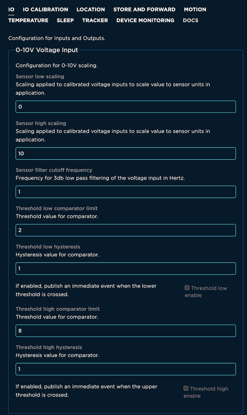
0-10V Voltage Input configuration
Configuration for 0-10V scaling.
Sensor low scaling configuration
| Field | Value |
|---|---|
| Schema ID | #/properties/io/voltage/sensorlow |
| Title | Sensor low scaling |
| Description | Scaling applied to calibrated voltage inputs to scale value to sensor units in application. |
| Example values |
Sensor high scaling configuration
| Field | Value |
|---|---|
| Schema ID | #/properties/io/voltage/sensorhigh |
| Title | Sensor high scaling |
| Description | Scaling applied to calibrated voltage inputs to scale value to sensor units in application. |
| Default Value | 10 |
| Example values | 100 |
Sensor filter cutoff frequency configuration
| Field | Value |
|---|---|
| Schema ID | #/properties/io/voltage/sensorfc |
| Title | Sensor filter cutoff frequency |
| Description | Frequency for 3db low pass filtering of the voltage input in Hertz. |
| Default Value | 1 |
| Example values | 12 |
Threshold low comparator limit configuration
| Field | Value |
|---|---|
| Schema ID | #/properties/io/voltage/threshlow |
| Title | Threshold low comparator limit |
| Description | Threshold value for comparator. |
| Default Value | 2 |
| Example values | 100 |
Threshold low hysteresis configuration
| Field | Value |
|---|---|
| Schema ID | #/properties/io/voltage/hystlow |
| Title | Threshold low hysteresis |
| Description | Hysteresis value for comparator. |
| Default Value | 1 |
| Example values | 100 |
Threshold low enable configuration
| Field | Value |
|---|---|
| Schema ID | #/properties/io/voltage/th_low_en |
| Title | Threshold low enable |
| Description | If enabled, publish an immediate event when the lower threshold is crossed. |
| Example values | true |
Threshold high comparator limit configuration
| Field | Value |
|---|---|
| Schema ID | #/properties/io/voltage/threshhigh |
| Title | Threshold high comparator limit |
| Description | Threshold value for comparator. |
| Default Value | 8 |
| Example values | 100 |
Threshold high hysteresis configuration
| Field | Value |
|---|---|
| Schema ID | #/properties/io/voltage/hysthigh |
| Title | Threshold high hysteresis |
| Description | Hysteresis value for comparator. |
| Default Value | 1 |
| Example values | 100 |
Threshold high enable configuration
| Field | Value |
|---|---|
| Schema ID | #/properties/io/voltage/th_high_en |
| Title | Threshold high enable |
| Description | If enabled, publish an immediate event when the upper threshold is crossed. |
| Example values | true |
4-20mA Current Input configuration
Configuration for 4-20mA scaling.
Sensor low scaling configuration
| Field | Value |
|---|---|
| Schema ID | #/properties/io/current/sensorlow |
| Title | Sensor low scaling |
| Description | Scaling applied to calibrated current inputs to scale value to sensor units in application. |
| Default Value | 0.004 |
| Example values |
Sensor high scaling configuration
| Field | Value |
|---|---|
| Schema ID | #/properties/io/current/sensorhigh |
| Title | Sensor high scaling |
| Description | Scaling applied to calibrated current inputs to scale value to sensor units in application. |
| Default Value | 0.02 |
| Example values | 10 |
Sensor filter cutoff frequency configuration
| Field | Value |
|---|---|
| Schema ID | #/properties/io/current/sensorfc |
| Title | Sensor filter cutoff frequency |
| Description | Frequency for 3db low pass filtering of the current input in Hertz. |
| Default Value | 1 |
| Example values | 12 |
Threshold low comparator limit configuration
| Field | Value |
|---|---|
| Schema ID | #/properties/io/current/threshlow |
| Title | Threshold low comparator limit |
| Description | Threshold value for comparator. |
| Default Value | 0.008 |
| Example values | 100 |
Threshold low hysteresis configuration
| Field | Value |
|---|---|
| Schema ID | #/properties/io/current/hystlow |
| Title | Threshold low hysteresis |
| Description | Hysteresis value for comparator. |
| Default Value | 0.002 |
| Example values | 100 |
Threshold low enable configuration
| Field | Value |
|---|---|
| Schema ID | #/properties/io/current/th_low_en |
| Title | Threshold low enable |
| Description | If enabled, publish an immediate event when the lower threshold is crossed. |
| Example values | true |
Threshold high comparator limit configuration
| Field | Value |
|---|---|
| Schema ID | #/properties/io/current/threshhigh |
| Title | Threshold high comparator limit |
| Description | Threshold value for comparator. |
| Default Value | 0.016 |
| Example values | 100 |
Threshold high hysteresis configuration
| Field | Value |
|---|---|
| Schema ID | #/properties/io/current/hysthigh |
| Title | Threshold high hysteresis |
| Description | Hysteresis value for comparator. |
| Default Value | 0.002 |
| Example values | 100 |
Threshold high enable configuration
| Field | Value |
|---|---|
| Schema ID | #/properties/io/current/th_high_en |
| Title | Threshold high enable |
| Description | If enabled, publish an immediate event when the upper threshold is crossed. |
| Example values | true |
Threshold low fault comparator limit configuration
| Field | Value |
|---|---|
| Schema ID | #/properties/io/current/th_fault_low |
| Title | Threshold low fault comparator limit |
| Description | Threshold value, in milliamps, for fault comparator. |
| Default Value | 0.003875 |
| Example values | 100 |
Threshold low fault hysteresis configuration
| Field | Value |
|---|---|
| Schema ID | #/properties/io/current/hyst_fault_low |
| Title | Threshold low fault hysteresis |
| Description | Hysteresis value, in milliamps, for fault comparator. |
| Default Value | 0.000125 |
| Example values | 100 |
Threshold low fault enable configuration
| Field | Value |
|---|---|
| Schema ID | #/properties/io/current/th_fault_low_en |
| Title | Threshold low fault enable |
| Description | If enabled, publish an immediate event when the lower threshold is crossed. |
| Example values | true |
Threshold high fault comparator limit configuration
| Field | Value |
|---|---|
| Schema ID | #/properties/io/current/th_fault_high |
| Title | Threshold high fault comparator limit |
| Description | Threshold value, in milliamps, for fault comparator. |
| Default Value | 0.016 |
| Example values | 100 |
Threshold high fault hysteresis configuration
| Field | Value |
|---|---|
| Schema ID | #/properties/io/current/hyst_fault_high |
| Title | Threshold high fault hysteresis |
| Description | Hysteresis value, in milliamps, for fault comparator. |
| Default Value | 0.002 |
| Example values | 100 |
Threshold high fault enable configuration
| Field | Value |
|---|---|
| Schema ID | #/properties/io/current/th_fault_high_en |
| Title | Threshold high fault enable |
| Description | If enabled, publish an immediate event when the upper threshold is crossed. |
| Example values | true |
24V Digital Input configuration
Configuration for optoisolated digial input.
Publish immediately on input change configuration
| Field | Value |
|---|---|
| Schema ID | #/properties/io/input/immediate |
| Title | Publish immediately on input change |
| Description | If enabled, publish an immediate event when the digital input changes. |
| Example values | true |
Edge detection configuration
| Field | Value |
|---|---|
| Schema ID | #/properties/io/input/edge |
| Title | Edge detection |
| Description | Publish on input change based on edge detected. |
| Default Value | none |
| Enumeration values | none, rising, falling, both |
I/O card calibration
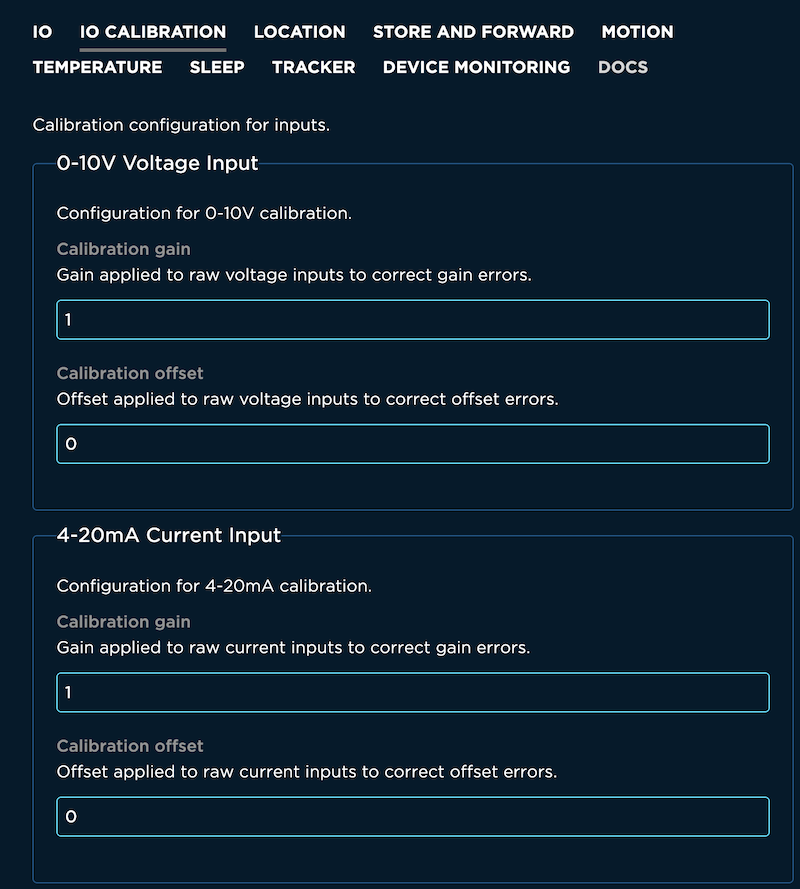
0-10V Voltage Input configuration
Configuration for 0-10V calibration.
Calibration gain configuration
| Field | Value |
|---|---|
| Schema ID | #/properties/iocal/voltage/calgain |
| Title | Calibration gain |
| Description | Gain applied to raw voltage inputs to correct gain errors. |
| Default Value | 1 |
| Example values | 0.95 |
Calibration offset configuration
| Field | Value |
|---|---|
| Schema ID | #/properties/iocal/voltage/caloffset |
| Title | Calibration offset |
| Description | Offset applied to raw voltage inputs to correct offset errors. |
| Example values | -0.01 |
4-20mA Current Input configuration
Configuration for 4-20mA calibration.
Calibration gain configuration
| Field | Value |
|---|---|
| Schema ID | #/properties/iocal/current/calgain |
| Title | Calibration gain |
| Description | Gain applied to raw current inputs to correct gain errors. |
| Default Value | 1 |
| Example values | 0.95 |
Calibration offset configuration
| Field | Value |
|---|---|
| Schema ID | #/properties/iocal/current/caloffset |
| Title | Calibration offset |
| Description | Offset applied to raw current inputs to correct offset errors. |
| Example values | -0.01 |
Modbus
The following settings, available in Monitor Edge v2, are for the Modbus (RS485) support on the Monitor One I/O card.
RS-485 Baud configuration
| Field | Value |
|---|---|
| Schema ID | #/properties/modbus_rs485/baud |
| Title | RS-485 Baud |
| Description | Baud rate to operate the RS-485 bus. |
| Default Value | 38400 |
| Enumeration values | 1200, 2400, 4800, 9600, 19200, 28800, 38400, 57600, 76800, 115200 |
RS-485 Parity Bits configuration
| Field | Value |
|---|---|
| Schema ID | #/properties/modbus_rs485/parity |
| Title | RS-485 Parity Bits |
| Description | Specifies partiy type used for the RS-485 bus. |
| Default Value | none |
| Enumeration values | none, even |
Modbus Inter Message Delay configuration
| Field | Value |
|---|---|
| Schema ID | #/properties/modbus_rs485/imd |
| Title | Modbus Inter Message Delay |
| Description | Delay between the last Modbus response and the next transmission in milliseconds. This is used for rate limiting transactions. |
Modbus Server Enable configuration
| Field | Value |
|---|---|
| Schema ID | #/properties/modbus1/enable |
| Title | Modbus Server Enable |
| Description | If enabled, poll the given Modbus server address. |
| Example values | true |
Modbus Server ID configuration
| Field | Value |
|---|---|
| Schema ID | #/properties/modbus1/id |
| Title | Modbus Server ID |
| Description | The remote device server ID (also known as slave ID). Range: 1-255. |
| Default Value | 1 |
Modbus Timeout configuration
| Field | Value |
|---|---|
| Schema ID | #/properties/modbus1/timeout |
| Title | Modbus Timeout |
| Description | Allowable time to wait for a response in milliseconds. Range: 0-10000. |
| Default Value | 2000 |
Polling Interval configuration
| Field | Value |
|---|---|
| Schema ID | #/properties/modbus1/poll |
| Title | Polling Interval |
| Description | Defines the frequency (in seconds) in which the register will be polled and results published. |
| Default Value | 1 |
Publish polled value configuration
| Field | Value |
|---|---|
| Schema ID | #/properties/modbus1/publish |
| Title | Publish polled value |
| Description | Select when to publish the polled value. |
| Default Value | always |
| Enumeration values | always |
Modbus Function configuration
| Field | Value |
|---|---|
| Schema ID | #/properties/modbus1/function |
| Title | Modbus Function |
| Description | Type of read function. |
| Default Value | coil |
| Enumeration values | coil, discrete_input, input_register, holding_register |
Register Address configuration
| Field | Value |
|---|---|
| Schema ID | #/properties/modbus1/address |
| Title | Register Address |
| Description | Address to read from, zero based. Range: 0-65535. |
Modbus data type configuration
| Field | Value |
|---|---|
| Schema ID | #/properties/modbus1/type |
| Title | Modbus data type |
| Description | Type of data being read. |
| Default Value | uint16 |
| Enumeration values | int16, uint16, int32, uint32, float32_abcd, float32_badc, float32_cdab, float32_dcba, bits |
Mask Value configuration
| Field | Value |
|---|---|
| Schema ID | #/properties/modbus1/mask |
| Title | Mask Value |
| Description | 16-bit bitmask to apply to read value to isolate bits. Use 65535 if masking is not required. Range: 0-65535. |
| Default Value | 65535 |
Shift Value configuration
| Field | Value |
|---|---|
| Schema ID | #/properties/modbus1/shift |
| Title | Shift Value |
| Description | Shifting, in bits, to right shift read value after masking. Use 0 if shifting is not required. Range: 0-15. |
Offset Value configuration
| Field | Value |
|---|---|
| Schema ID | #/properties/modbus1/offset |
| Title | Offset Value |
| Description | Offset applied to masked and shifted input. This represents “b” in “y = mx + b”. Use 0 if not required (float variable). |
| Example values | 0.5 |
Scaling Value configuration
| Field | Value |
|---|---|
| Schema ID | #/properties/modbus1/scale |
| Title | Scaling Value |
| Description | Scaling applied to masked and shifted input. This represents “m” in “y = mx + b”. Use 1 if not required (float variable). |
| Default Value | 1 |
| Example values | 10 |
Modbus Server Enable configuration
| Field | Value |
|---|---|
| Schema ID | #/properties/modbus2/enable |
| Title | Modbus Server Enable |
| Description | If enabled, poll the given Modbus server address. |
| Example values | true |
Modbus Server ID configuration
| Field | Value |
|---|---|
| Schema ID | #/properties/modbus2/id |
| Title | Modbus Server ID |
| Description | The remote device server ID (also known as slave ID). Range: 1-255. |
| Default Value | 1 |
Modbus Timeout configuration
| Field | Value |
|---|---|
| Schema ID | #/properties/modbus2/timeout |
| Title | Modbus Timeout |
| Description | Allowable time to wait for a response in milliseconds. Range: 0-10000. |
| Default Value | 2000 |
Polling Interval configuration
| Field | Value |
|---|---|
| Schema ID | #/properties/modbus2/poll |
| Title | Polling Interval |
| Description | Defines the frequency (in seconds) in which the register will be polled and results published. |
| Default Value | 1 |
Publish polled value configuration
| Field | Value |
|---|---|
| Schema ID | #/properties/modbus2/publish |
| Title | Publish polled value |
| Description | Select when to publish the polled value. |
| Default Value | always |
| Enumeration values | always |
Modbus Function configuration
| Field | Value |
|---|---|
| Schema ID | #/properties/modbus2/function |
| Title | Modbus Function |
| Description | Type of read function. |
| Default Value | coil |
| Enumeration values | coil, discrete_input, input_register, holding_register |
Register Address configuration
| Field | Value |
|---|---|
| Schema ID | #/properties/modbus2/address |
| Title | Register Address |
| Description | Address to read from, zero based. Range: 0-65535. |
Modbus data type configuration
| Field | Value |
|---|---|
| Schema ID | #/properties/modbus2/type |
| Title | Modbus data type |
| Description | Type of data being read. |
| Default Value | uint16 |
| Enumeration values | int16, uint16, int32, uint32, float32_abcd, float32_badc, float32_cdab, float32_dcba, bits |
Mask Value configuration
| Field | Value |
|---|---|
| Schema ID | #/properties/modbus2/mask |
| Title | Mask Value |
| Description | 16-bit bitmask to apply to read value to isolate bits. Use 65535 if masking is not required. Range: 0-65535. |
| Default Value | 65535 |
Shift Value configuration
| Field | Value |
|---|---|
| Schema ID | #/properties/modbus2/shift |
| Title | Shift Value |
| Description | Shifting, in bits, to right shift read value after masking. Use 0 if shifting is not required. Range: 0-15. |
Offset Value configuration
| Field | Value |
|---|---|
| Schema ID | #/properties/modbus2/offset |
| Title | Offset Value |
| Description | Offset applied to masked and shifted input. This represents “b” in “y = mx + b”. Use 0 if not required (float variable). |
| Example values | 0.5 |
Scaling Value configuration
| Field | Value |
|---|---|
| Schema ID | #/properties/modbus2/scale |
| Title | Scaling Value |
| Description | Scaling applied to masked and shifted input. This represents “m” in “y = mx + b”. Use 1 if not required (float variable). |
| Default Value | 1 |
| Example values | 10 |
Modbus Server Enable configuration
| Field | Value |
|---|---|
| Schema ID | #/properties/modbus3/enable |
| Title | Modbus Server Enable |
| Description | If enabled, poll the given Modbus server address. |
| Example values | true |
Modbus Server ID configuration
| Field | Value |
|---|---|
| Schema ID | #/properties/modbus3/id |
| Title | Modbus Server ID |
| Description | The remote device server ID (also known as slave ID). Range: 1-255. |
| Default Value | 1 |
Modbus Timeout configuration
| Field | Value |
|---|---|
| Schema ID | #/properties/modbus3/timeout |
| Title | Modbus Timeout |
| Description | Allowable time to wait for a response in milliseconds. Range: 0-10000. |
| Default Value | 2000 |
Polling Interval configuration
| Field | Value |
|---|---|
| Schema ID | #/properties/modbus3/poll |
| Title | Polling Interval |
| Description | Defines the frequency (in seconds) in which the register will be polled and results published. |
| Default Value | 1 |
Publish polled value configuration
| Field | Value |
|---|---|
| Schema ID | #/properties/modbus3/publish |
| Title | Publish polled value |
| Description | Select when to publish the polled value. |
| Default Value | always |
| Enumeration values | always |
Modbus Function configuration
| Field | Value |
|---|---|
| Schema ID | #/properties/modbus3/function |
| Title | Modbus Function |
| Description | Type of read function. |
| Default Value | coil |
| Enumeration values | coil, discrete_input, input_register, holding_register |
Register Address configuration
| Field | Value |
|---|---|
| Schema ID | #/properties/modbus3/address |
| Title | Register Address |
| Description | Address to read from, zero based. Range: 0-65535. |
Modbus data type configuration
| Field | Value |
|---|---|
| Schema ID | #/properties/modbus3/type |
| Title | Modbus data type |
| Description | Type of data being read. |
| Default Value | uint16 |
| Enumeration values | int16, uint16, int32, uint32, float32_abcd, float32_badc, float32_cdab, float32_dcba, bits |
Mask Value configuration
| Field | Value |
|---|---|
| Schema ID | #/properties/modbus3/mask |
| Title | Mask Value |
| Description | 16-bit bitmask to apply to read value to isolate bits. Use 65535 if masking is not required. Range: 0-65535. |
| Default Value | 65535 |
Shift Value configuration
| Field | Value |
|---|---|
| Schema ID | #/properties/modbus3/shift |
| Title | Shift Value |
| Description | Shifting, in bits, to right shift read value after masking. Use 0 if shifting is not required. Range: 0-15. |
Offset Value configuration
| Field | Value |
|---|---|
| Schema ID | #/properties/modbus3/offset |
| Title | Offset Value |
| Description | Offset applied to masked and shifted input. This represents “b” in “y = mx + b”. Use 0 if not required (float variable). |
| Example values | 0.5 |
Scaling Value configuration
| Field | Value |
|---|---|
| Schema ID | #/properties/modbus3/scale |
| Title | Scaling Value |
| Description | Scaling applied to masked and shifted input. This represents “m” in “y = mx + b”. Use 1 if not required (float variable). |
| Default Value | 1 |
| Example values | 10 |
Devices and SIM cards
There are multiple lists of devices and SIM card lists, and this section describes which one is which.
Devices - sandbox
The devices list includes devices that are claimed to your account, that you are the owner of, in your free developer sandbox. These devices count against your free plan limit of 100 devices.
It also includes devices that are claimed to your account, that are part of a product (free, basic, or enterprise). Devices that are claimed to your account but are part of product do not count toward your free device limit.
The exception is free plan products owned by you, in which case all devices, whether claimed by you or not, count toward the 100 device limit. Only devices claimed by you show up in this list; the others are only in the product device list but still count toward the limit.
In the developer sandbox, non-product, there is no add devices button. The intended paths to add a device are:
- Using the Particle CLI
- Using setup.particle.io
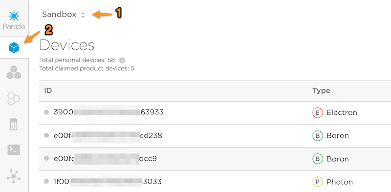
- Sandbox is selected in the upper left (1).
- The Devices icon is selected in the left navigation bar (2).
SIM cards - sandbox
Cellular devices with Particle SIM cards, either built-in (MFF2) or plastic nano SIM cards (4FF) show up in this list.
In the developer sandbox, non-product, there is no import button. The intended paths to activate a SIM card are:
- From setup.particle.io where you can set up a cellular device with a SIM card, or activate just the SIM card
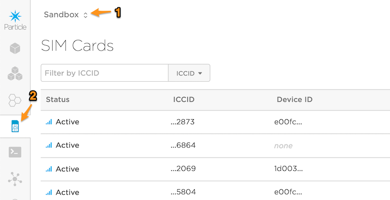
- Sandbox is selected in the upper left (1).
- The SIM cards icon is selected in the left navigation bar (2).
Products - sandbox
The products list in the sandbox shows:
- Free plan products that you are the owner of
- Free plan products that you are a team member of
You can tell by the email address under the product description as this is the owner of the product (3). If you are the owner, all devices in that product count toward your 100 device limit.
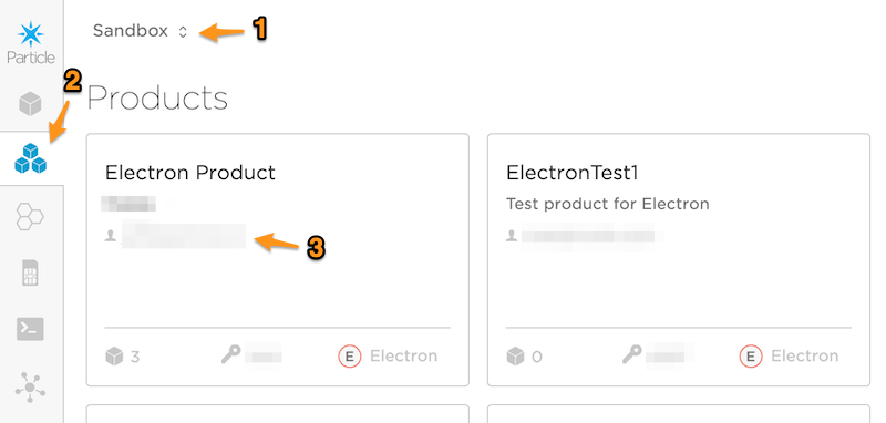
- Sandbox is selected in the upper left (1).
- The Products icon is selected in the left navigation bar (2).
Products devices - sandbox
This list shows all devices that are included in a product, regardless of claiming.
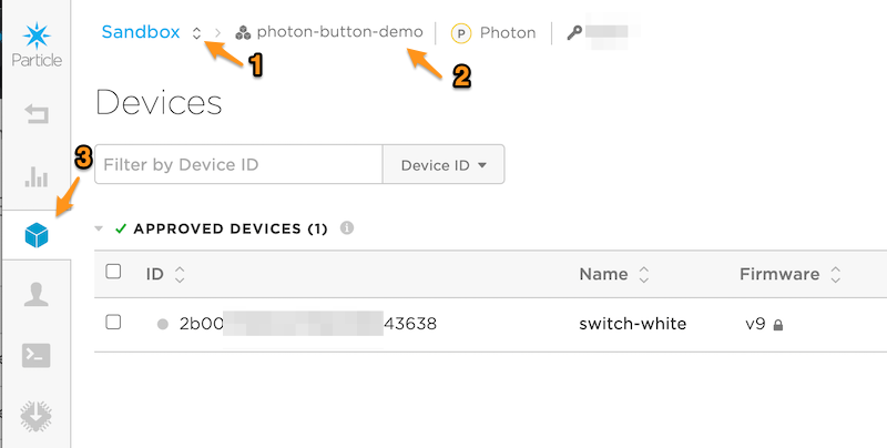
- Sandbox is selected in the upper left (1).
- The Products icon is selected, then a product. The current product is shown at the top (2).
- The Devices icon is selected in the left navigation bar (3). Make sure you select the Devices icon inside the product, not the one at the top level of the console!
If you click the ... button on the right side of the product device list, there are three options:
- Mark as development device
- Unclaim device
- Remove device
Add Devices allows a single device ID, or a file of device IDs, to be added to a product. Within the free sandbox, there is a limit of 100 devices. This is across all device types, and is further reduced by the non-product devices claimed by the product owner.
If you wish to both unclaim and remove a device, always select Unclaim device first. If you remove the device from the product, it will no longer appear in the list.
The List Devices Tool can be used to export a list of devices to a spreadsheet.
The Device Remove Tool can be used to simplify the process of removing multiple devices.
Products SIM cards - sandbox
Cellular devices with Particle SIM cards, either built-in (MFF2) or plastic nano SIM cards (4FF), show up in this list. The cellular usage by these SIM cards count against the cellular data limit for the user account that owns the product.
If the 100 MB per month limit is exceeded for the free sandbox account, the account is paused until the next billing cycle.
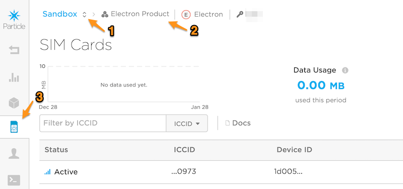
- Sandbox is selected in the upper left (1).
- The Products icon is selected, then a product. The current product is shown at the top (2).
- The SIM cards icon is selected in the left navigation bar (3). Make sure you select the SIM cards icon inside the product, not the one at the top level of the console!
Import SIM cards adds a SIM to the product. This is normally only necessary if you have an Electron 2G/3G with a 4FF plastic nano SIM card. For all devices with a built-in MFF2 SMD SIM card, if you add the device to the product, its matching SIM card is automatically added as well.
Products - organization
The products list in the organization shows all products in the organization you have selected. The Organization Team configuration determines what access you have (Administrator, Developer, View-Only, etc.) for all products in the organization.
It is also possible to invite team members to the product who are not part of the organization. For example, if you hire a outside contractor to work on a specific project you could grant developer access to only that product, not the whole organization.
Organizations are used for both basic and enterprise plans. An organization is a collection of products, shared team access controls, and shared billing that span across all products. This makes it much easier to manage multiple products. Every member of an organization also has a free sandbox associated with their account.
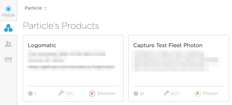
Products devices - organization
This list shows all devices that are included in a product, regardless of claiming.
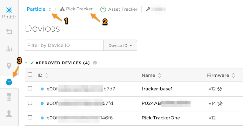
- An organization is selected in the upper left (1).
- The Products icon is selected, then a product. The current product is shown at the top (2).
- The Devices icon is selected in the left navigation bar (3). Make sure you select the Devices icon inside the product, not the one at the top level of the console!
Add Devices allows a single device ID, or a file of device IDs, to be added to a product.
Products SIM cards - organization
Cellular devices with Particle SIM cards, either built-in (MFF2) or plastic nano SIM cards (4FF), show up in this list. The cellular usage by these SIM cards count against the cellular data limit for the organization that owns the product.
In the basic plan, for each class of class device (cellular or tracker), there is a pool of data based on the number of blocks. If you exceed this pool of cellular data, a new block is added to the organization.
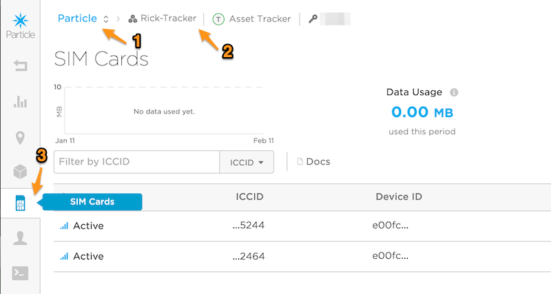
- An organization is selected in the upper left (1).
- The Products icon is selected, then a product. The current product is shown at the top (2).
- The SIM cards icon is selected in the left navigation bar (3). Make sure you select the SIM cards icon inside the product, not the one at the top level of the console!