
M-SoM from E-Series migration guide
 |  |
Pictures are not the same scale
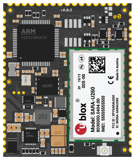
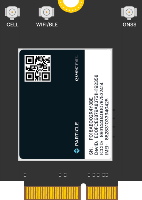
The M-SoM (system-on-a-module) is a 4th-generation cellular and Wi-Fi device. It plugs into an M.2 NGFF connector on your custom circuit board and is intended for mass production use.
Like the E-Series module, it requires your own custom base board. One difference is that the M-SoM does not contain the PMIC and fuel gauge chips that the E-Series does.
Additionally, different dimensions makes it possible to include a LTE Cat 1 with 2G/3G fallback cellular modem, such as the Quectel EG91-E on the B524.
All E-Series models (except for the E404X) have been deprecated. It is recommended that you migrate to the B-SoM or M-SoM, and it is required to get LTE Cat 1 with 2G/3G fallback support in Europe, Australia, and New Zealand. While the E404X has the same footprint as the other E-Series modules, it contains the same MCU as the B-SoM.
| Feature | E-Series SoM | E-Series Base Board | M-SoM | SoM Base Board |
|---|---|---|---|---|
| U.FL Antenna Connector | ✓ | ✓ | Optional | |
| MFF2 SMD Particle SIM2 | ✓ | ✓ | ||
| USB Connector | Optional | Optional | ||
| Status LED | Optional | Optional | ||
| Reset and Mode Buttons | Optional | Optional | ||
| Battery Connector | Optional | Optional | ||
| PMIC and Fuel Gauge1 | ✓ | Optional |
1The PMIC (power management IC) and fuel gauge are used with battery-powered applications. They're omitted from the SoM as they are not needed for externally powered solutions (grid or automotive power, for example). Additionally, you may want to use different models if you are making a solar-powered device, or using a different battery technology or multiple battery pack.
2The built-in Particle SIM card is free for use up to certain limits, no credit card required.
Datasheets
Certification
When migrating to a new device, recertification is typically required. If you are using the standard Particle antennas you often only need to complete the less expensive unintentional radiator testing of your completed assembly, however in some cases intentional radiator testing could be required.
Prototyping
The M-SoM cannot be used without a base board. Typically you will create your own board, however there are two off-the-shelf options available:
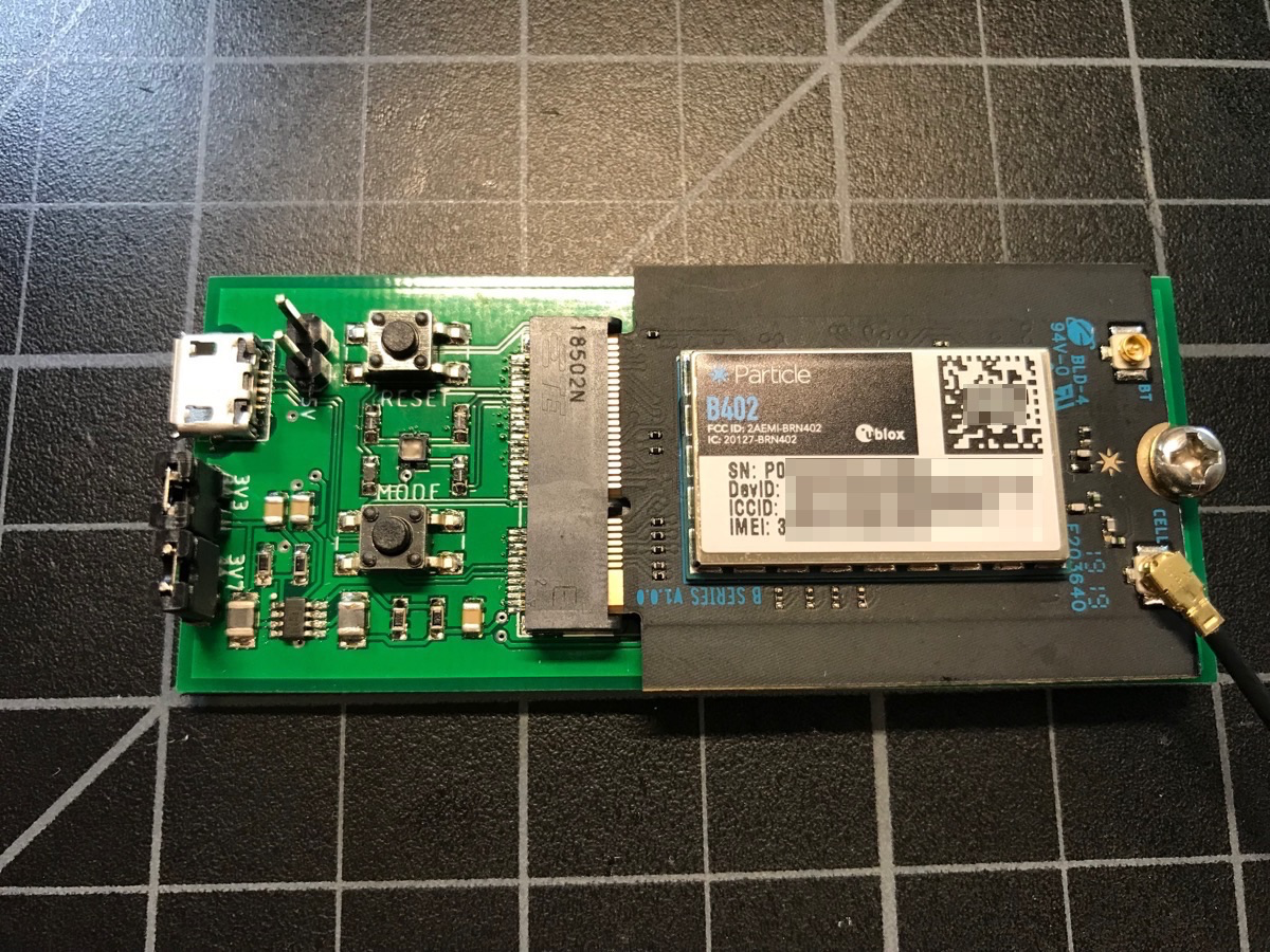
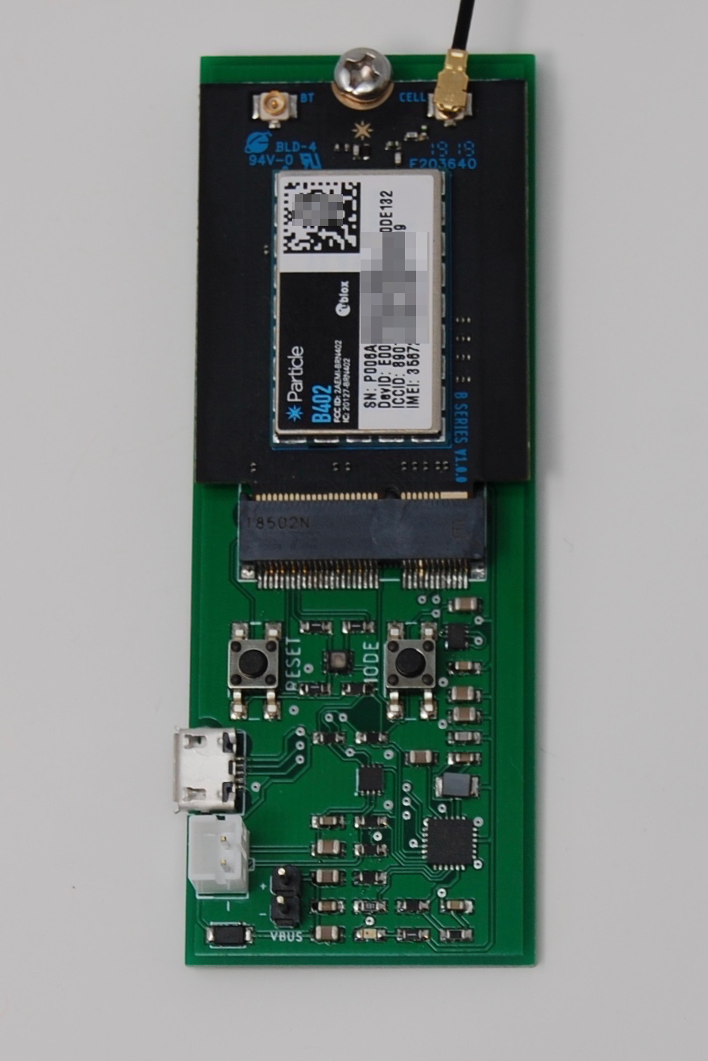
B-Series Eval board
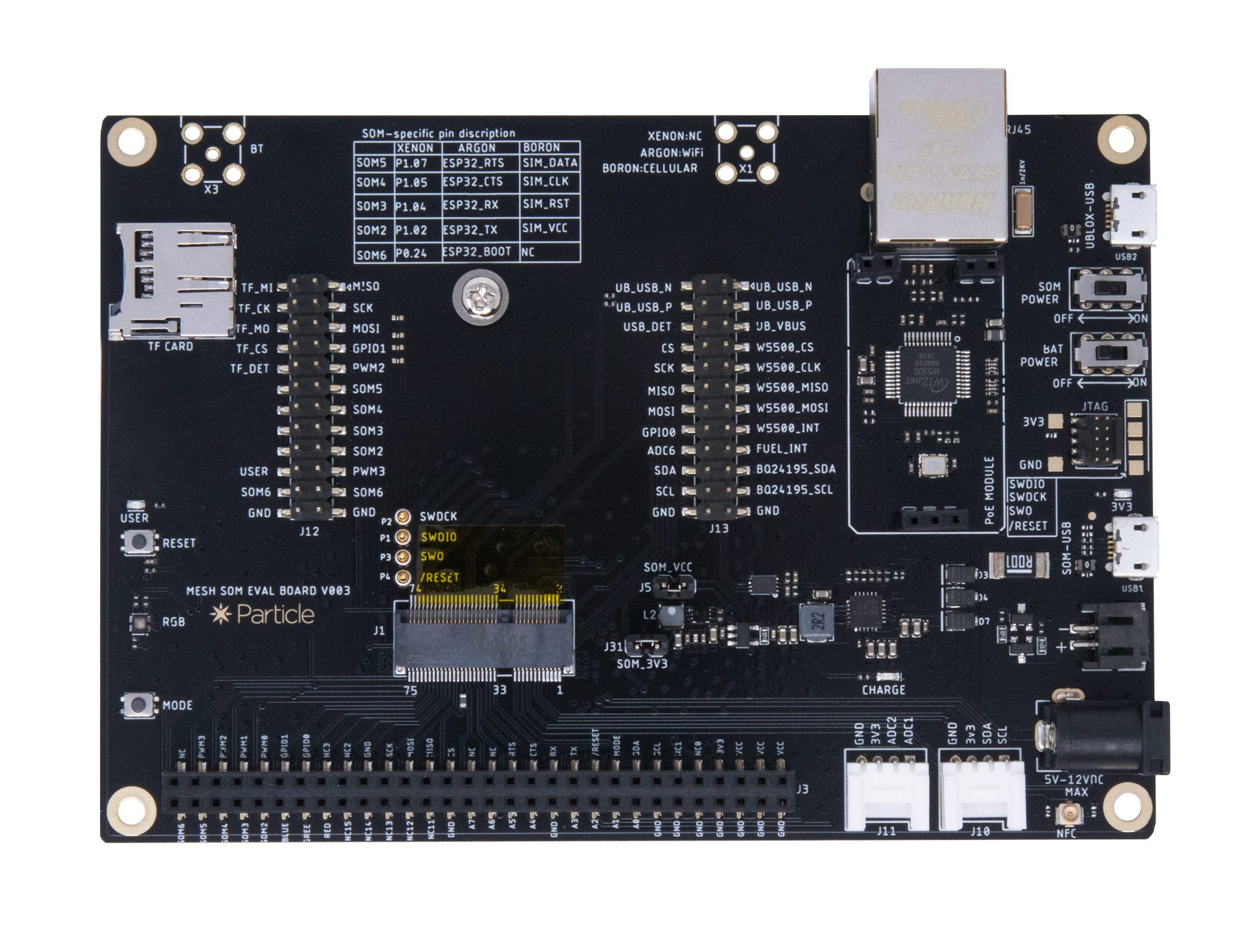
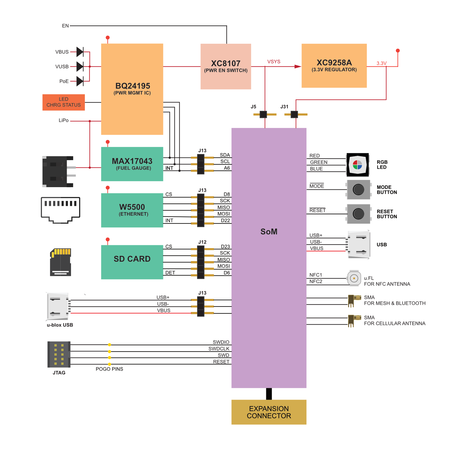
The B-Series evaluation board provides a variety of interfaces and access to all ports and pins on the M-SoM. You can use the expansion connector to connect the evaluation board to a breadboard for prototyping. You can also add sensors and accessories using the Grove expansion connectors.
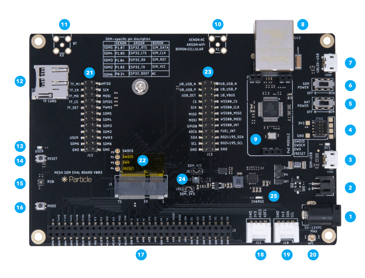
| Num | ID | Description |
|---|---|---|
| 1 | External Power | 5-12 VDC. Minimum power requirements are 5VDC @500mA (when using the LiPo battery) or 5VDC @2000mA (without LiPo battery). |
| 2 | LiPo Battery connector | Plug in the LiPo battery here. |
| 3 | SoM USB port | This is the module's main USB port that connects to the microcontroller. |
| 4 | JTAG connector | This can plug directly into the Particle debugger ribbon cable. |
| 5 | Battery switch | Controls power between the LiPo connector and the charge controller. |
| 6 | SoM power switch | Controls 3V3 power to the SoM |
| 7 | u-blox USB port | This USB port connects directly to the u-blox module for firmware updates. |
| 8 | Ethernet connector | RJ45 connector for twisted pair Ethernet, 10 or 100 Mbit/sec. |
| 9 | PoE connector | Connect for the Particle PoE adapter for power-over-Ethernet. |
| 10 | Cellular antenna | Connector for an external SMA connected cellular antenna. |
| 11 | Bluetooth antenna | Connector for an external SMA connected antenna for Bluetooth networking. |
| 12 | TF/SD Card | MicroSD card slot. |
| 13 | User LED | Blue LED connected to pin D7. |
| 14 | Reset Button | This is same as the RESET button on the Boron. |
| 15 | RGB LED | System status indicator RGB LED. |
| 16 | Mode Button | This is the same as the MODE button on the Boron. |
| 17 | Expansion Connector | Allows easy access to SoM IO pins. |
| 18 | Grove Analog Port | Connects to Seeed Studio Grove analog and digital boards. |
| 19 | Grove I2C Port | Connects to Seeed Studio Grove I2C boards. |
| 20 | NFC Antenna | U.FL connector for an NFC antenna (optional). |
| 21 | Jumpers J12 | Enable or disable various features on the evaluation board. |
| 22 | SoM connector | M.2 connector for the B-Series SoM. |
| 23 | Jumpers J13 | Enable or disable various features on the evaluation board. |
| 24 | Power Jumpers | Enable or disable power from the evaluation board. |
| 25 | Charge LED | Indicate LiPo is charging. |
Mikroe Gen 3 SoM shield
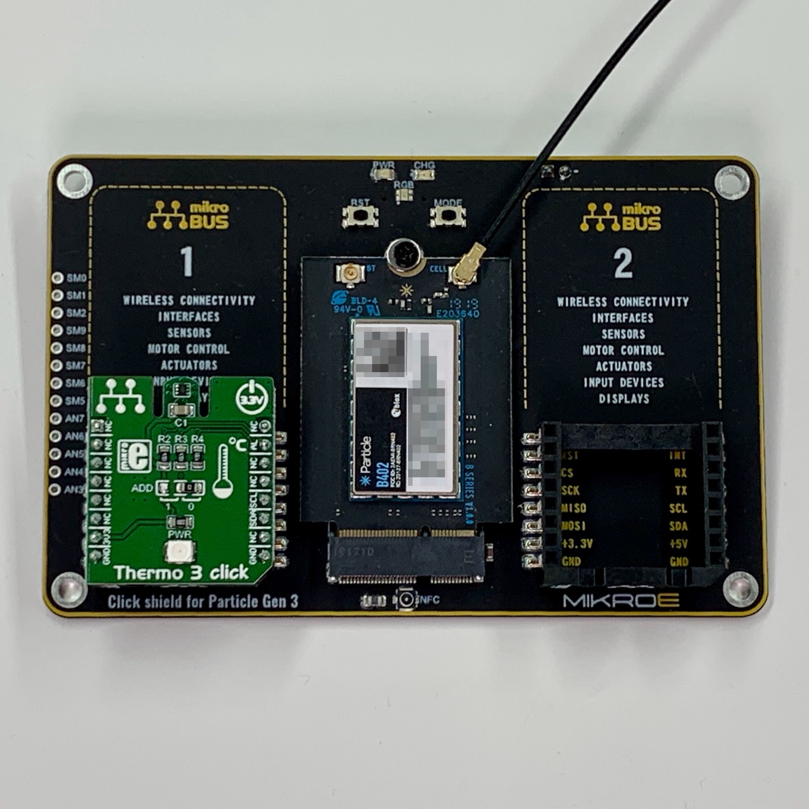
The Gen 3 SoM shield connects a B-Series SoM to mikroBUS Click boards:
| M.2 Pin | Generic SoM | Gen 3 | mikroBUS #1 | mikroBUS #2 |
|---|---|---|---|---|
| 20 | SCL | D1 | SCL | SCL |
| 22 | SDA | D0 | SDA | SDA |
| 23 | ADC0 | A0 | RST2 | |
| 33 | ADC1 | A1 | AN1 | |
| 35 | ADC2 | A2 | AN2 | |
| 36 | TX | TX/D9 | TX | TX |
| 37 | ADC3 | A3 | ||
| 38 | RX | TX/D10 | RX | RX |
| 41 | ADC4 | A4 | ||
| 43 | ADC5 | A5 | ||
| 45 | ADC6 | A6 | ||
| 47 | ADC7 | A7 | ||
| 48 | CS | D8 | CS1 | |
| 50 | MISO | MISO/D11 | MISO | MISO |
| 52 | MOSI | MOSI/D12 | MOSI | MOSI |
| 54 | SCK | SCK/D13 | SCK | SCK |
| 62 | GPIO0 | D22 | INT1 | |
| 64 | GPIO1 | D23 | INT2 | |
| 66 | PWM0 | D4 | CS2 | |
| 68 | PWM1 | D5 | PWM1 | |
| 70 | PWM2 | D6 | PWM2 | |
| 72 | PWM3 | D7 | RST1 |
There is a huge library of mikroBUS Click expansion boards, however the caveat is that most of them do not already have a Particle software library. If the board is for a common sensor or chip, however, existing Particle libraries for the chip will typically work, even if not designed work with the Click.
For more information, see the Mikroe community page.
Creating a board
First SoM board tutorial
The SoM first board tutorial shows how to get started with the M.2 SoM boards by making the simplest possible design. It's an introduction to working with surface mount components you will need in order to make your own SoM base board.
Basic SoM design
This design is a bit more complicated, and includes the PMIC and Fuel Gauge chips that are present on the E-Series:
- RGB LED
- bq24195 PMIC
- MAX17043 Fuel Gauge
- USB Connector
- LiPo Connector (JST-PH)
- M.2 SoM Connector
This is the basic set of features you'll probably want to include in a LiPo battery-powered design. The Evaluation Board is also a good reference to use. This design, however, is simple enough that it can be hand-assembled, though you still need a reflow oven and some of the parts (in particular the fuel gauge and PMIC) are tiny and there are a lot of them.
This board a two-layer circuit board so it can be manufactured inexpensively and edited using the free version of Eagle CAD.
As this board doesn't really do much, you'll unlikely use it as-is, but you can use it as a tutorial for how to hook up the PMIC and fuel gauge.
Power requirements
The M-SoM has peak power usage that is higher than the E-Series SoM. Be sure the check the guidelines below carefully.
As the M-SoM does not include a built-in power supply like the E-Series SoM, you may want to consider using the PM-BAT power module that includes the PMIC, fuel gauge, and voltage regulators.
VCC
VCC is used to supply power to the cellular module. The recommended input voltage range on this pin is between 3.6V to 4.2V DC. This can be connected directly to a 3.7V LiPo battery. Make sure that the supply can handle currents of at least 2 A.
If you are not using a battery, or using a battery of a different voltage, you should use a regulator to supply 3.7V to 4.2V at 2A. You may want to add additional bulk capacitors to handle the short, high current peak usage when the cellular modem is transmitting.
3V3
The E-Series module includes a built-in PMIC and 3V3 regulator, but you must provide your own with the M-SoM.
3V3 is used to supply power to MCU, Wi-Fi, BLE, logic ICs, memory, etc.. Make sure that the supply can handle a minimum of 500 mA.
These limits do not include any 3.3V peripherals on your base board, so that may increase the current requirements.
The M-SoM requires significantly more peak current than the E-Series.
Power supply requirements:
- 3.3V output
- Maximum 5% voltage drop
- 100 mV peak-to-peak ripple maximum
- 500 mA minimum output current at 3.3V recommended for future compatibility
- Maintain these values at no-load as well as maximum load
In some cases, it may be necessary to add a supervisory/reset IC, such as the Richtek RT9818C or SG Micro SGM809-RXN3L/TR:
- If your power supply has a slew rate from 1.5V to 3.0V slower than 15 ms, a reset IC is required.
- If your power supply at power off cannot be guaranteed to drop below 0.3V before powering back up, a reset IC required.
See supervisory reset in the M-SoM datasheet, for additional information.
Software differences
User firmware binary size
One major advantage is that user firmware binaries can be up to 2048 Kbytes, instead of 128 Kbytes on Gen 2 devices.
Flash file system
There is a 2 MB flash file system for storing user data on the M-SoM. This is not available on the E-Series (except for the E404X).
Combined and resumable OTA
Over-the-air (OTA) updates have two features that can improve the speed and reliability of OTA updates:
- Combined OTA can combine Device OS and user firmware updates into a single binary that requires only one download and one reboot to install.
- Resumable OTA allows an update to resume from the point it stopped, instead of starting over from the beginning if interrupted.
Asset OTA
Asset OTA makes it possible to include bundled assets in an OTA software update that can be delivered to other processors and components in your product.
Increased API field limits
The maximum size of a variable, function parameter, or publish is 1024 bytes on the M-SoM vs. 864 bytes on the E-Series.
| API Field | E-Series | M-SoM |
|---|---|---|
| Variable Key | 64 | 64 |
| Variable Data | 864 | 1024 |
| Function Key | 64 | 64 |
| Function Argument | 864 | 1024 |
| Publish/Subscribe Event Name | 64 | 64 |
| Publish/Subscribe Event Data | 864 | 1024 |
- These comparisons are between the STM32F205-based E-Series models, other than the E404X. The API field limits for the E404X (nRF52840) are the same as as the M-SoM.
Hardware differences
MCU
| Measure | E-Series | M-SoM |
|---|---|---|
| MCU | STM32F205 | RTL8722DM |
| Manufacturer | ST Microelectronics | Realtek |
| Processor | ARM Cortex M3 | ARM Cortex M33 |
| Speed | 120 MHz | 200 MHz |
| Available RAM | 55 KB | 3500 KB |
| User firmware size | 128 KB | 2048 KB |
| Flash file system | 2 MB | |
| Hardware floating point | ✓ | |
| Secure Boot | ✓ |
- These comparisons are between the STM32F205-based E-Series models, other than the E404X. The specifications for the E404X (nRF52840) are different.
BLE (Bluetooth LE)
- Bluetooth LE (BLE 5.0) is supported on M-SoM but not the E-Series (except for the E404X, which does support BLE).
GPIO
| E-Series Pin | E-Series Pin Name | E-Series GPIO | M-SoM Pin | M-SoM Pin Name | M-SoM GPIO |
|---|---|---|---|---|---|
| 26 | A0 | ✓ | 23 | A0 / D19 | ✓ |
| 25 | A1 | ✓ | 33 | A1 / D18 | ✓ |
| 24 | A2 | ✓ | 35 | A2 / D17 | ✓ |
| 23 | A3 | ✓ | 37 | A3 / D16 | ✓ |
| 22 | A4 | ✓ | 41 | A4 / D15 | ✓ |
| 21 | A5 | ✓ | 43 | A5 / D14 | ✓ |
| 53 | A5 / D14 | ✓ | |||
| 33 | B0 | ✓ | |||
| 32 | B1 | ✓ | |||
| 31 | B2 | ✓ | |||
| 30 | B3 | ✓ | |||
| 29 | B4 | ✓ | |||
| 28 | B5 | ✓ | |||
| 49 | C0 | ✓ | |||
| 48 | C1 | ✓ | |||
| 47 | C2 | ✓ | |||
| 46 | C3 | ✓ | |||
| 45 | C4 | ✓ | |||
| 44 | C5 | ✓ | |||
| 42 | D0 | ✓ | 22 | D0 | ✓ |
| 41 | D1 | ✓ | 20 | D1 | ✓ |
| 40 | D2 | ✓ | 42 | D2 | ✓ |
| 19 | D20 | ✓ | |||
| 17 | D21 | ✓ | |||
| 62 | D22 | ✓ | |||
| 64 | D23 | ✓ | |||
| 58 | D24 | ✓ | |||
| 60 | D25 | ✓ | |||
| 59 | D26 | ✓ | |||
| 55 | D27 | ✓ | |||
| 39 | D3 | ✓ | 40 | D3 | ✓ |
| 38 | D4 | ✓ | 66 | D4 | ✓ |
| 37 | D5 | ✓ | 68 | D5 | ✓ |
| 36 | D6 | ✓ | 70 | D6 | ✓ |
| 35 | D7 | ✓ | 72 | D7 | ✓ |
| 48 | D8 | ✓ | |||
| 20 | DAC / A6 | ✓ | 45 | A6 / D29 | ✓ |
| 50 | MISO / D11 | ✓ | |||
| 52 | MOSI / D12 | ✓ | |||
| 17 | RX | ✓ | 38 | RX / D10 | ✓ |
| 54 | SCK / D13 | ✓ | |||
| 16 | TX | ✓ | 36 | TX / D9 | ✓ |
| 19 | WKP / A7 | ✓ | 47 | A7 / WKP | ✓ |
The MCP23008 is an 8-port GPIO expander that connects to I2C and works well with Gen 3 devices. You can connect up to 8 of them to a single I2C interface. the MCP23017 has 16-ports, and you can also connect 8 of them, for a total of 128 GPIO ports.
The application note AN013 Tracker GPIO shows how you can add additional GPIO to your Tracker One using the external M8 connector, however the same technique can also be used with the M-SoM. It includes both 3.3V and 5V design options.
5V tolerance
The other difference in the GPIO between Gen 2 and the M-SoM is with 5V tolerance. While both devices are 3.3V devices and only will drive 3.3V, the I/O pins on Gen 2 devices (with the exception of A3 and A6) are 5V tolerant. This allows a Gen 2 device to connect to some 5V peripherals directly.
You must not connect 5V peripherals to a Gen 3 or Gen 4 device. This includes GPIO, ports (serial, I2C, SPI), and ADC.
Interfacing with 5V peripherals can be done with a level shifter, a MOSFET, or a 5V GPIO expander.
SPI
- The M-SoM and E-Series both have two SPI ports.
- In most cases, you can share a single SPI bus with many peripherals.
- On the E-Series, SPI1 and SPI2 share the same MCU SPI interface but have different pin locations. You can only use one or the other.
| E-Series Pin | E-Series Pin Name | E-Series SPI | M-SoM Pin | M-SoM Pin Name | M-SoM SPI |
|---|---|---|---|---|---|
| 24 | A2 | SPI (SS) | 35 | A2 / D17 | |
| 23 | A3 | SPI (SCK) | 37 | A3 / D16 | |
| 22 | A4 | SPI (MISO) | 41 | A4 / D15 | |
| 21 | A5 | SPI (MOSI) | 43 | A5 / D14 | |
| 48 | C1 | SPI2 (MOSI) | |||
| 47 | C2 | SPI2 (MISO) | |||
| 46 | C3 | SPI2 (SCK) | |||
| 40 | D2 | SPI1 (MOSI) | 42 | D2 | SPI1 (SCK) |
| 39 | D3 | SPI1 (MISO) | 40 | D3 | SPI1 (SS) |
| 38 | D4 | SPI1 (SCK) | 66 | D4 | |
| 37 | D5 | SPI1 (SS) | 68 | D5 | |
| 48 | D8 | SPI (SS) | |||
| 50 | MISO / D11 | SPI (MISO) | |||
| 52 | MOSI / D12 | SPI (MOSI) | |||
| 17 | RX | 38 | RX / D10 | SPI1 (MISO) | |
| 54 | SCK / D13 | SPI (SCK) | |||
| 16 | TX | 36 | TX / D9 | SPI1 (MOSI) |
Serial (UART)
There are more UART ports on the E-Series than the M-SoM. If you need more hardware serial ports, the best option is to use the SC16IS740 or its relatives like the SC16IS750. These devices connect by I2C or SPI, and you can add multiple ports this way.
| E-Series | M-SoM | |
|---|---|---|
| Buffer size | 64 bytes | 2048 bytes |
| 7-bit mode | ✓ | ✓ |
| 8-bit mode | ✓ | ✓ |
| 9-bit mode | ✓ | |
| 1 stop bit | ✓ | ✓ |
| 2 stop bits | ✓ | ✓ |
| No parity | ✓ | ✓ |
| Even parity | ✓ | ✓ |
| Odd parity | ✓ | ✓ |
| Break detection | ✓ | |
| LIN bus support | ✓ | |
| Half duplex | ✓ | |
| CTS/RTS flow control | ✓1 |
1CTS/RTS flow control only on Serial1. It is optional.
Supported Baud Rates:
| Baud Rate | E-Series | M-SoM |
|---|---|---|
| 110 | ✓ | |
| 300 | ✓ | |
| 600 | ✓ | |
| 1200 | ✓ | ✓ |
| 2400 | ✓ | ✓ |
| 4800 | ✓ | ✓ |
| 9600 | ✓ | ✓ |
| 14400 | ✓ | |
| 19200 | ✓ | ✓ |
| 28800 | ✓ | |
| 38400 | ✓ | ✓ |
| 57600 | ✓ | ✓ |
| 76800 | ✓ | |
| 115200 | ✓ | ✓ |
| 128000 | ✓ | |
| 153600 | ✓ | |
| 230400 | ✓ | ✓ |
| 380400 | ✓ | |
| 460800 | ✓ | |
| 500000 | ✓ | |
| 921600 | ✓ | |
| 1000000 | ✓ | |
| 1382400 | ✓ | |
| 1444400 | ✓ | |
| 1500000 | ✓ | |
| 1843200 | ✓ | |
| 2000000 | ✓ | |
| 2100000 | ✓ | |
| 2764800 | ✓ | |
| 3000000 | ✓ | |
| 3250000 | ✓ | |
| 3692300 | ✓ | |
| 3750000 | ✓ | |
| 4000000 | ✓ | |
| 6000000 | ✓ |
| E-Series Pin | E-Series Pin Name | E-Series Serial | M-SoM Pin | M-SoM Pin Name | M-SoM Serial |
|---|---|---|---|---|---|
| 49 | C0 | Serial5_RX | |||
| 48 | C1 | Serial5_TX | |||
| 47 | C2 | Serial4 RX | |||
| 46 | C3 | Serial4 TX | |||
| 40 | D2 | 42 | D2 | Serial1 (RTS) | |
| 58 | D24 | Serial2 (TX) | |||
| 60 | D25 | Serial2 (RX) | |||
| 39 | D3 | 40 | D3 | Serial1 (CTS) | |
| 52 | RGBB | Serial2 (RX) | 65 | RGBB | |
| 53 | RGBG | Serial2 (TX) | 63 | RGBG | |
| 17 | RX | Serial1 (RX) | 38 | RX / D10 | Serial1 (RX) |
| 16 | TX | Serial1 (TX) | 36 | TX / D9 | Serial1 (TX) |
Analog input (ADC)
The M-SoM does not have an many ADC ports as the E-Series. You can add additional ADC ports using a SPI or I2C ADC.
| E-Series Pin | E-Series Pin Name | E-Series ADC | M-SoM Pin | M-SoM Pin Name | M-SoM ADC |
|---|---|---|---|---|---|
| 26 | A0 | ✓ | 23 | A0 / D19 | ✓ |
| 25 | A1 | ✓ | 33 | A1 / D18 | ✓ |
| 24 | A2 | ✓ | 35 | A2 / D17 | ✓ |
| 23 | A3 | ✓ | 37 | A3 / D16 | ✓ |
| 22 | A4 | ✓ | 41 | A4 / D15 | ✓ |
| 21 | A5 | ✓ | 43 | A5 / D14 | ✓ |
| 53 | A5 / D14 | ✓ | |||
| 31 | B2 | ✓ | |||
| 30 | B3 | ✓ | |||
| 29 | B4 | ✓ | |||
| 28 | B5 | ✓ | |||
| 20 | DAC / A6 | ✓ | 45 | A6 / D29 | ✓ |
| 19 | WKP / A7 | ✓ | 47 | A7 / WKP | ✓ |
I2C
| E-Series Pin | E-Series Pin Name | E-Series I2C | M-SoM Pin | M-SoM Pin Name | M-SoM I2C |
|---|---|---|---|---|---|
| 45 | C4 | Wire1 (SDA) | |||
| 44 | C5 | Wire1 (SCL) | |||
| 42 | D0 | Wire (SDA) | 22 | D0 | Wire (SDA) |
| 41 | D1 | Wire (SCL) | 20 | D1 | Wire (SCL) |
- 1 I2C on M-SoM. While it appears that there are 2 on the E-Series, they're just alternative pin assignments and you can really only use one at a time.
- You can generally have many devices on a single I2C bus.
- If you have I2C address conflicts you can use an I2C multiplexer like the TCA9548A.
- The E-Series I2C is 5V tolerant. This is not the case on the M-SoM, be sure you don't have pull-ups to 5V!
- If you need to interface to a 5V I2C bus you will need an I2C level shifter such as the PCA9306.
- On the M-SoM (and P2 and Photon 2), the only valid I2C clock speeds are
CLOCK_SPEED_100KHZandCLOCK_SPEED_400KHZ. Other speeds are not supported at this time.
PWM (Pulse-width modulation)
These are differences in pins that support PWM between the E-Series and M-SoM.
| E-Series Pin | E-Series Pin Name | E-Series PWM | < SoM Pin | < SoM Pin Name | < SoM PWM | < SoM Hardware Timer |
|---|---|---|---|---|---|---|
| 26 | A0 | 23 | A0 / D19 | ✓ | ||
| 25 | A1 | 33 | A1 / D18 | ✓ | ||
| 22 | A4 | ✓ | 41 | A4 / D15 | ||
| 21 | A5 | ✓ | 43 | A5 / D14 | ✓ | |
| 53 | A5 / D14 | ✓ | ||||
| 33 | B0 | ✓ | ||||
| 32 | B1 | ✓ | ||||
| 31 | B2 | ✓ | ||||
| 30 | B3 | ✓ | ||||
| 45 | C4 | ✓ | ||||
| 44 | C5 | ✓ | ||||
| 42 | D0 | ✓ | 22 | D0 | ||
| 41 | D1 | ✓ | 20 | D1 | ||
| 40 | D2 | ✓ | 42 | D2 | ||
| 39 | D3 | ✓ | 40 | D3 | ||
| 38 | D4 | 66 | D4 | ✓ | ||
| 37 | D5 | 68 | D5 | ✓ | ||
| 36 | D6 | 70 | D6 | ✓ | ||
| 35 | D7 | 72 | D7 | ✓ | ||
| 20 | DAC / A6 | 45 | A6 / D29 | ✓ | ||
| 50 | MISO / D11 | ✓ | ||||
| 52 | MOSI / D12 | ✓ | ||||
| 17 | RX | ✓ | 38 | RX / D10 | ✓ | |
| 16 | TX | ✓ | 36 | TX / D9 | ✓ | |
| 19 | WKP / A7 | ✓ | 47 | A7 / WKP |
PWM - M-SoM
All available PWM pins on the M-SoM share a single timer. This means that they must all share a single frequency, but can have different duty cycles.
It is also possible to add an external PWM driver such as the PCA9685 which adds 16 outputs via I2C. You can add 62 of these to a single I2C bus for 992 PWM outputs! The Adafruit_PWMServoDriver library supports this chip on all Particle devices.
PWM - Gen 2
On the Electron and E-Series, this function works on pins D0, D1, D2, D3, A4, A5, WKP, RX, TX, B0, B1, B2, B3, C4, and C5 with a caveat: PWM timer peripheral is duplicated on two pins (A5/D2) and (A4/D3) for 7 total independent PWM outputs. For example: PWM may be used on A5 while D2 is used as a GPIO, or D2 as a PWM while A5 is used as an analog input. However A5 and D2 cannot be used as independently controlled PWM outputs at the same time.
Internal pull-up or pull-down
Internal (MCU) pull-up and pull-down can be enabled using the pinMode() function and INPUT_PULLUP or INPUT_PULLDOWN.
On the M-SoM, different GPIO pins have different pull values. On the E-Series pull is always approximately 40K.
Retained memory
The M-SoM has limited support for retained memory, also referred to as Backup RAM or SRAM.
Retained memory is preserved on RTL872x devices in the following cases:
| Case | Saved |
|---|---|
| When entering sleep modes | 5.3.1 and later |
| OTA firmware updates | 5.3.1 and later |
System.backupRamSync() |
5.3.1 and later |
System.reset() |
Not saved |
| Reset button or reset pin | Not saved |
| Every 10 seconds | 5.3.1 to 5.8.0 only |
Calling System.backupRamSync() will manually save the contents of retained memory to a dedicated flash page on the RTL872x processor and will be restored after the device is reset. You should avoid saving the data extremely frequently as it is slower than RAM and will cause flash wear and is relatively slow to execute.
Prior to Device OS 5.3.1, retained memory is not supported on RTL872x devices. The flash file system can be used, or you can use an external chip such as an I2C or SPI FRAM.
Retained memory is 3068 bytes.
Flash file system
The E-Series did not have a flash file system.
The M-SoM has 2 MB flash file system using the same POSIX API as Gen 3 devices. A small amount of space is reserved for system use including configuration data. Most of the space is available for user application use.
EEPROM
The EEPROM emulation API is the same across the E-Series and M-SoM.
- The E-Series had 2047 bytes of emulated EEPROM.
- The M-SoM has 4096 bytes of emulated EEPROM. On the M-SoM, P2, Photon 2, and Gen 3 devices, the EEPROM is actually just a file on the flash file system.
Interrupts
Interrupts - Gen 2
Not supported on the Electron/E series (you can't use attachInterrupt on these pins):
- D0, A5 (shared with MODE button)
- D7 (shared with BATT_INT_PC13)
- C1 (shared with RXD_UC)
- C2 (shared with RI_UC)
No restrictions on the Electron/E-Series (all of these can be used at the same time):
- D5, D6
Shared on the Electron/E-Series (only one pin for each bullet item can be used at the same time):
- D1, A4, B1
- D2, A0, A3
- D3, DAC
- D4, A1
- A2, C0
- A7 (WKP), B2, B4
- B0, C5
- B3, B5
- C3, TX
- C4, RX
Interrupts - M-SoM
There are no restrictions on interrupt pins on the M-SoM.
DAC
Gen 2 devices have two DAC (digital-to-analog converter), on pins A3 and A6.
The M-SoM and Gen 3 devices do not have built-in DAC, however they can easily be added by I2C or SPI to your base board.
CAN bus
- The M-SoM and Gen 3 devices do not support CAN on the MCU.
- The Tracker SoM includes CAN via a MCP25625 CAN interface with integrated transceiver.
- Both the MCP2515 and MCP25625 work with the library used on the Tracker and can be used to add CAN to other Gen 3 devices.
Sleep
In
HIBERNATEsleep mode, both the M-SoM and E-Series put pin inOUTPUTmode into high-impedance state.In
STOPandULTRA_LOW_POWERsleep modes, the M-SoM preserves the digital output, but the E-Series puts the pins inOUTPUTmode into high-impedance state.In
HIBERNATEsleep mode, on the M-SoM, pin D21 does not maintainINPUT_PULLUPorINPUT_PULLDOWNwhile asleep.
M-SoM pins related to HIBERNATE sleep mode:
| Pin | Pin Name | Description | Interface | MCU |
|---|---|---|---|---|
| 36 | TX / D9 | Serial TX, PWM, GPIO, SPI1 MOSI, I2S MCLK | Pin can wake from HIBERNATE sleep | PA[12] |
| 38 | RX / D10 | Serial RX, PWM, GPIO, SPI1 MISO | Pin can wake from HIBERNATE sleep | PA[13] |
| 40 | D3 | D3 GPIO, Serial1 CTS flow control (optional), SPI1 SS | Pin can wake from HIBERNATE sleep | PA[15] |
| 42 | D2 | D2 GPIO, Serial RTS flow control (optional), SPI1 SCK | Pin can wake from HIBERNATE sleep | PA[14] |
| 47 | A7 / WKP | A7 Analog In, WKP, GPIO D28 | Pin can wake from HIBERNATE sleep | PA[20] |
| 48 | D8 | D8 GPIO, SPI SS | Pin can wake from HIBERNATE sleep | PA[19] |
| 50 | MISO / D11 | D11 GPIO, PWM, SPI MISO | Pin can wake from HIBERNATE sleep | PA[17] |
| 52 | MOSI / D12 | D12 GPIO, PWM, SPI MOSI | Pin can wake from HIBERNATE sleep | PA[16] |
| 54 | SCK / D13 | D13 GPIO, SPI SCK | Pin can wake from HIBERNATE sleep | PA[18] |
E-Series pins related to HIBERNATE sleep mode:
| Pin | Pin Name | Description | Interface | MCU |
|---|---|---|---|---|
| 19 | WKP / A7 | WKP/A7 Wakeup (active high), analog in, GPIO. | Only this pin can wake from HIBERNATE sleep mode. | PA0 |
RTC (Real-time clock)
The E-Series module has support for an external lithium coin cell battery or supercap to power the STM32 internal RTC via the VBAT pin.
The M-SoM MCU does not have a dedicated RTC module that can be externally powered. This is also the case with the P2, Photon 2, and Gen 3 devices. If you need an externally powered RTC, one option is the AM1805/AB1805 real-time clock and hardware watchdog module, which is used on the Tracker SoM.
USB
- Both the E-Series and M-SoM assume the USB connector will be mounted on your base board. It is recommended that you add one to your base board for programming and troubleshooting.
- Gen 2 devices can emulate a USB mouse or keyboard over the USB port. This feature is available on the M-SoM but not available on Gen 3 (including B-SoM).
- Gen 2 devices can support two separate USB serial emulation streams over the USB port. Gen 3 devices only support the normal
Serialinterface.
| USB Feature | E-Series | M-SoM | B-SoM |
|---|---|---|---|
Secondary USB serial emulation USBSerial1 |
✓ | ||
| USB keyboard emulation | ✓ | ✓ | |
| USB mouse emulation | ✓ | ✓ |
PMIC and Fuel gauge
The E-Series, E-Series, Boron, and Tracker SoM all include the PMIC (bq24195) and battery fuel gauge (MAX17043) on the module itself.
On the M-SoM, the PMIC and fuel gauge are optional. For example, if you are powering by an external power supply and not using a battery, you can omit the components entirely.
PMIC Notes
When using the B-Series SoM with a bq24195 PMIC, note the following:
By default, the bq24195 sets the input current limit, which affects powering by VIN and VUSB, to 100 mA. This affects the VSYS output of the PMIC, which powers both the cellular modem and 3V3 supply, and is not enough to power the B-Series SoM in normal operation.
If your device has the default firmware (Tinker), it will attempt to connect to the cloud, brown out due to insufficient current, then the device will reset. This may result in what appears to be the status LED blinking white, but is actually rolling reboot caused by brownout.
A factory new B-Series SoM does not enable the PMIC setup. To enable the use of the bq21415, you must enable the system power feature PMIC_DETECTION in your code. This defaults to off because the B-Series SoM can be used without a PMIC, or with a different PMIC, and also requires I2C on D0/D1, and some base boards may use those pins as GPIO.
Because the input current limit does not affect the battery input (Li+), for troubleshooting purposes it can be helpful to attach a battery to help rule out input current limit issues. It's also possible to supply 3.7V via a bench power supply to the battery input, instead of VIN.
The input current limit can result in a situation where you can't bring up a B-Series SoM because it browns out continuously, but also cannot flash code to it to stop if from browning out. There are two general solutions:
- Attach a battery or supply by Li+ when bringing up a board.
- Use SWD/JTAG and reset halt the MCU. This will prevent it from connecting to the cloud, so you can flash Device OS and firmware to it by SWD.
The input current limit is actually controlled by three factors:
- The power source max current setting in the PMIC. The default is 900 mA. It can be set to 100, 150, 500, 900, 1200, 1500, 2000, or 3000 mA.
- It is also limited by the hardware ILIM resistor. On Particle devices with a built-in PMIC, this is set to 1590 mA, but if you are implementing your own PMIC hardware, you can adjust this higher.
- When connected by USB, it will use DPDM, current negotiation via the USB DP (D+) and DM (D-) lines.
Note that some 2A tablet chargers and multi-port USB power supplies supply 2A but do not implement DPDM; these will be treated as if VIN was used, and you must set the power source current, otherwise the input current will be limited to 900 mA, which is not enough to power a 2G/3G cellular modem without an attached battery.
Antennas
The M-SoM has U.FL antenna connectors:
- Cellular
- Wi-Fi and BLE (shared)
- GNSS (optional)
Full module pin comparison
3V3
| E-Series | M-SoM | ||
|---|---|---|---|
| ∆ | Pin Number | 9 | 10 |
| Pin Name | 3V3 | 3V3 | |
| ∆ | Description | Regulated 3.3V DC output, maximum load 800 mA. Cannot be used as a power input. | System power in, supply a fixed 3.3V power, 500 mA minimum |
A0
| E-Series | M-SoM | ||
|---|---|---|---|
| ∆ | Pin Number | 26 | 23 |
| Pin Name | A0 | A0 | |
| ∆ | Pin Alternate Name | n/a | D19 |
| ∆ | Description | A0 Analog in, GPIO | A0 Analog in, GPIO, PWM |
| Supports digitalRead | Yes | Yes | |
| Supports digitalWrite | Yes | Yes | |
| Supports analogRead | Yes | Yes | |
| ∆ | Supports analogWrite (PWM) | No | Yes |
| ∆ | Supports tone | No | Yes |
| ∆ | Supports attachInterrupt | Yes. D2, A0, and A3 share the same interrupt handler. | Yes |
| ∆ | Internal pull resistance | 40K | 42K |
| ∆ | Input is 5V Tolerant | Yes | No |
A1
| E-Series | M-SoM | ||
|---|---|---|---|
| ∆ | Pin Number | 25 | 33 |
| Pin Name | A1 | A1 | |
| ∆ | Pin Alternate Name | n/a | D18 |
| ∆ | Description | A1 Analog in, GPIO | A1 Analog in, GPIO, PWM |
| Supports digitalRead | Yes | Yes | |
| Supports digitalWrite | Yes | Yes | |
| Supports analogRead | Yes | Yes | |
| ∆ | Supports analogWrite (PWM) | No | Yes |
| ∆ | Supports tone | No | Yes |
| ∆ | Supports attachInterrupt | Yes. D4 and A1 share the same interrupt handler. | Yes |
| ∆ | Internal pull resistance | 40K | ??? |
| ∆ | Input is 5V Tolerant | Yes | No |
A2
| E-Series | M-SoM | ||
|---|---|---|---|
| ∆ | Pin Number | 24 | 35 |
| Pin Name | A2 | A2 | |
| ∆ | Pin Alternate Name | n/a | D17 |
| ∆ | Description | A2 Analog in, GPIO, SPI SS | A2 Analog in, GPIO |
| Supports digitalRead | Yes | Yes | |
| Supports digitalWrite | Yes | Yes | |
| Supports analogRead | Yes | Yes | |
| ∆ | SPI interface | SS. Use SPI object. This is only the default SS/CS pin, you can use any GPIO instead. | n/a |
| ∆ | Supports attachInterrupt | Yes. A2 and C0 share the same interrupt handler. | Yes |
| ∆ | Internal pull resistance | 40K | 22K |
| ∆ | Input is 5V Tolerant | Yes | No |
A3
| E-Series | M-SoM | ||
|---|---|---|---|
| ∆ | Pin Number | 23 | 37 |
| Pin Name | A3 | A3 | |
| ∆ | Pin Alternate Name | n/a | D16 |
| ∆ | Description | A3 True analog out, analog in, GPIO. | A3 Analog in, PDM CLK, GPIO |
| Supports digitalRead | Yes | Yes | |
| Supports digitalWrite | Yes | Yes | |
| Supports analogRead | Yes | Yes | |
| ∆ | Supports analogWrite (DAC) | Yes | No |
| ∆ | SPI interface | SCK. Use SPI object. | n/a |
| ∆ | Supports attachInterrupt | Yes. D2, A0, and A3 share the same interrupt handler. | Yes |
| ∆ | Internal pull resistance | 40K | 2.1K |
A4
| E-Series | M-SoM | ||
|---|---|---|---|
| ∆ | Pin Number | 22 | 41 |
| Pin Name | A4 | A4 | |
| ∆ | Pin Alternate Name | n/a | D15 |
| ∆ | Description | A4 Analog in, GPIO, SPI MISO. | A4 Analog in, PDM DAT, GPIO |
| Supports digitalRead | Yes | Yes | |
| Supports digitalWrite | Yes | Yes | |
| Supports analogRead | Yes | Yes | |
| ∆ | Supports analogWrite (PWM) | Yes. D3 and A4 share the same PWM channel and the PWM duty cycle is set for both. | No |
| ∆ | Supports tone | Yes. D3 and A4 share the same PWM channel and only one frequency can be set for both. | No |
| ∆ | SPI interface | MISO. Use SPI object. | n/a |
| ∆ | Supports attachInterrupt | Yes. D1 and A4 share the same interrupt handler. | Yes |
| ∆ | Internal pull resistance | 40K | 2.1K |
| ∆ | Input is 5V Tolerant | Yes | No |
A5
| E-Series | M-SoM | ||
|---|---|---|---|
| ∆ | Pin Number | 21 | 43 |
| Pin Name | A5 | A5 | |
| ∆ | Pin Alternate Name | n/a | D14 |
| ∆ | Description | A5 Analog in, GPIO, SPI MOSI. | A5 Analog in, PWM, GPIO, shared with pin 53 |
| Supports digitalRead | Yes | Yes | |
| Supports digitalWrite | Yes | Yes | |
| Supports analogRead | Yes | Yes | |
| ∆ | Supports analogWrite (PWM) | Yes. D2 and A5 share the same PWM channel and the PWM duty cycle is set for both. | Yes |
| ∆ | Supports tone | Yes. D2 and A5 share the same PWM channel and only one frequency can be set for both. | Yes |
| ∆ | SPI interface | MOSI. Use SPI object. | n/a |
| ∆ | Supports attachInterrupt | No | Yes |
| ∆ | Internal pull resistance | 40K | ??? |
| ∆ | Input is 5V Tolerant | Yes | No |
| ∆ | SWD interface | n/a | SWCLK. 40K pull-down at boot. |
| ∆ | Signal used at boot | n/a | SWCLK. 40K pull-down at boot. |
A5
| Added to M-SoM | |
|---|---|
| Pin Number | 53 |
| Pin Name | A5 |
| Pin Alternate Name | D14 |
| Description | A5 Analog in, PWM, GPIO, SWCLK, shared with pin 43 |
| Supports digitalRead | Yes |
| Supports digitalWrite | Yes |
| Supports analogRead | Yes |
| Supports analogWrite (PWM) | Yes |
| Supports tone | Yes |
| Supports attachInterrupt | Yes |
| Internal pull resistance | 42K |
| SWD interface | SWCLK. 40K pull-down at boot. |
| Signal used at boot | SWCLK. 40K pull-down at boot. |
AGND
| Added to M-SoM | |
|---|---|
| Pin Number | 39 |
| Pin Name | AGND |
| Description | Analog Ground. |
B0
| Removed from E-Series | |
|---|---|
| Pin Number | 33 |
| Pin Name | B0 |
| Description | B0, GPIO, PWM |
| Supports digitalRead | Yes |
| Supports digitalWrite | Yes |
| Supports analogWrite (PWM) | Yes |
| Supports tone | Yes |
| Supports attachInterrupt | Yes. B0 and C5 share the same interrupt handler. |
| Internal pull resistance | 40K |
| Input is 5V Tolerant | Yes |
B1
| Removed from E-Series | |
|---|---|
| Pin Number | 32 |
| Pin Name | B1 |
| Description | B1, GPIO, PWM |
| Supports digitalRead | Yes |
| Supports digitalWrite | Yes |
| Supports analogWrite (PWM) | Yes |
| Supports tone | Yes |
| Supports attachInterrupt | Yes. D1, A4, and B1 share the same interrupt handler. |
| Internal pull resistance | 40K |
| Input is 5V Tolerant | Yes |
B2
| Removed from E-Series | |
|---|---|
| Pin Number | 31 |
| Pin Name | B2 |
| Description | B2, analog in, GPIO, PWM |
| Supports digitalRead | Yes |
| Supports digitalWrite | Yes |
| Supports analogRead | Yes |
| Supports analogWrite (PWM) | Yes |
| Supports tone | Yes |
| Supports attachInterrupt | Yes. A7 (WKP), B2, and B4 share the same interrupt handler. |
| Internal pull resistance | 40K |
| Input is 5V Tolerant | Yes |
B3
| Removed from E-Series | |
|---|---|
| Pin Number | 30 |
| Pin Name | B3 |
| Description | B3, analog in, GPIO, PWM |
| Supports digitalRead | Yes |
| Supports digitalWrite | Yes |
| Supports analogRead | Yes |
| Supports analogWrite (PWM) | Yes |
| Supports tone | Yes |
| Supports attachInterrupt | Yes. B3 and B5 share the same interrupt handler. |
| Internal pull resistance | 40K |
| Input is 5V Tolerant | Yes |
B4
| Removed from E-Series | |
|---|---|
| Pin Number | 29 |
| Pin Name | B4 |
| Description | B4 Analog in, GPIO |
| Supports digitalRead | Yes |
| Supports digitalWrite | Yes |
| Supports analogRead | Yes |
| Supports attachInterrupt | Yes. A7 (WKP), B2, and B4 share the same interrupt handler. |
| Internal pull resistance | 40K |
| Input is 5V Tolerant | Yes |
B5
| Removed from E-Series | |
|---|---|
| Pin Number | 28 |
| Pin Name | B5 |
| Description | B5 Analog in, GPIO |
| Supports digitalRead | Yes |
| Supports digitalWrite | Yes |
| Supports analogRead | Yes |
| Supports attachInterrupt | Yes. B3 and B5 share the same interrupt handler. |
| Internal pull resistance | 40K |
| Input is 5V Tolerant | Yes |
C0
| Removed from E-Series | |
|---|---|
| Pin Number | 49 |
| Pin Name | C0 |
| Description | Serial5 RX (received data), GPIO. |
| Supports digitalRead | Yes |
| Supports digitalWrite | Yes |
| UART serial | RX. Use Serial5 object. |
| Supports attachInterrupt | Yes. A2 and C0 share the same interrupt handler. |
| Internal pull resistance | 40K |
| Input is 5V Tolerant | Yes |
C1
| Removed from E-Series | |
|---|---|
| Pin Number | 48 |
| Pin Name | C1 |
| Description | Serial5 TX (trasmitted data), SPI2, GPIO. |
| Supports digitalRead | Yes |
| Supports digitalWrite | Yes |
| UART serial | TX. Use Serial5 object. |
| SPI interface | MOSI. Use SPI2 object. |
| Internal pull resistance | 40K |
| Input is 5V Tolerant | Yes |
C2
| Removed from E-Series | |
|---|---|
| Pin Number | 47 |
| Pin Name | C2 |
| Description | Serial4 RX (received data), SPI2, GPIO. |
| Supports digitalRead | Yes |
| Supports digitalWrite | Yes |
| UART serial | RX. Use Serial4 object. |
| SPI interface | MISO. Use SPI2 object. |
| Internal pull resistance | 40K |
| Input is 5V Tolerant | Yes |
C3
| Removed from E-Series | |
|---|---|
| Pin Number | 46 |
| Pin Name | C3 |
| Description | Serial4 TX (transmitted data), SPI2, GPIO. |
| Supports digitalRead | Yes |
| Supports digitalWrite | Yes |
| UART serial | TX. Use Serial4 object. |
| SPI interface | SCK. Use SPI2 object. |
| Supports attachInterrupt | Yes. C3 and TX share the same interrupt handler. |
| Internal pull resistance | 40K |
| Input is 5V Tolerant | Yes |
C4
| Removed from E-Series | |
|---|---|
| Pin Number | 45 |
| Pin Name | C4 |
| Description | I2C, CAN, GPIO. |
| Supports digitalRead | Yes |
| Supports digitalWrite | Yes |
| Supports analogWrite (PWM) | Yes |
| Supports tone | Yes |
| I2C interface | SDA. Use Wire1 object. You can only use Wire or Wire1, not both! |
| Supports attachInterrupt | Yes. C4 and RX share the same interrupt handler. |
| CAN interface | CAN1_TX |
| Internal pull resistance | 40K |
| Input is 5V Tolerant | Yes |
C5
| Removed from E-Series | |
|---|---|
| Pin Number | 44 |
| Pin Name | C5 |
| Description | I2C, CAN, GPIO. |
| Supports digitalRead | Yes |
| Supports digitalWrite | Yes |
| Supports analogWrite (PWM) | Yes |
| Supports tone | Yes |
| I2C interface | SCL. Use Wire1 object. You can only use Wire or Wire1, not both! |
| Supports attachInterrupt | Yes. B0 and C5 share the same interrupt handler. |
| CAN interface | CAN1_RX |
| Internal pull resistance | 40K |
| Input is 5V Tolerant | Yes |
CELL USBD-
| Added to M-SoM | |
|---|---|
| Pin Number | 46 |
| Pin Name | CELL USBD- |
| Description | Cellular Modem USB Data- |
| Input is 5V Tolerant | Yes |
CELL USBD+
| Added to M-SoM | |
|---|---|
| Pin Number | 44 |
| Pin Name | CELL USBD+ |
| Description | Cellular Modem USB Data+ |
| Input is 5V Tolerant | Yes |
CELL VBUS
| Added to M-SoM | |
|---|---|
| Pin Number | 74 |
| Pin Name | CELL VBUS |
| Description | USB detect pin for cellular modem. 5V on this pin enables the Cellular Modem USB interface. |
| Input is 5V Tolerant | Yes |
CELL_RI
| Added to M-SoM | |
|---|---|
| Pin Number | 75 |
| Pin Name | CELL_RI |
| Description | CELL_RI, ring indicator output, leave unconnected. |
D0
| E-Series | M-SoM | ||
|---|---|---|---|
| ∆ | Pin Number | 42 | 22 |
| Pin Name | D0 | D0 | |
| ∆ | Description | D0 GPIO, I2C | D0 GPIO, I2C SDA |
| Supports digitalRead | Yes | Yes | |
| Supports digitalWrite | Yes | Yes | |
| ∆ | Supports analogWrite (PWM) | Yes | No |
| ∆ | Supports tone | Yes | No |
| ∆ | I2C interface | SDA. Use Wire object. Use 1.5K to 10K external pull-up resistor. Is 5V tolerant. | SDA. Use Wire object. Use 1.5K to 10K external pull-up resistor. |
| ∆ | Supports attachInterrupt | No | Yes |
| ∆ | Internal pull resistance | 40K | ??? |
| ∆ | Input is 5V Tolerant | Yes | No |
D1
| E-Series | M-SoM | ||
|---|---|---|---|
| ∆ | Pin Number | 41 | 20 |
| Pin Name | D1 | D1 | |
| ∆ | Description | D0 GPIO, I2C, CAN | D1 GPIO, I2C SCL |
| Supports digitalRead | Yes | Yes | |
| Supports digitalWrite | Yes | Yes | |
| ∆ | Supports analogWrite (PWM) | Yes | No |
| ∆ | Supports tone | Yes | No |
| ∆ | I2C interface | SCL. Use Wire object. Use 1.5K to 10K external pull-up resistor. Is 5V tolerant. | SCL. Use Wire object. Use 1.5K to 10K external pull-up resistor. |
| ∆ | Supports attachInterrupt | Yes. D1, A4, and B1 share the same interrupt handler. | Yes |
| ∆ | CAN interface | CAN2_TX | n/a |
| ∆ | Internal pull resistance | 40K | ??? |
| ∆ | Input is 5V Tolerant | Yes | No |
D2
| E-Series | M-SoM | ||
|---|---|---|---|
| ∆ | Pin Number | 40 | 42 |
| Pin Name | D2 | D2 | |
| ∆ | Description | D2 GPIO, SPI1, CAN | D2 GPIO, Serial RTS flow control (optional), SPI1 SCK |
| Supports digitalRead | Yes | Yes | |
| Supports digitalWrite | Yes | Yes | |
| ∆ | Supports analogWrite (PWM) | Yes. D2 and A5 share the same PWM channel and the PWM duty cycle is set for both. | No |
| ∆ | Supports tone | Yes. D2 and A5 share the same PWM channel and only one frequency can be set for both. | No |
| ∆ | UART serial | n/a | RTS. Use Serial1 object. |
| ∆ | SPI interface | MOSI. Use SPI1 object. | SCK. Use SPI1 object. |
| ∆ | Supports attachInterrupt | Yes. D2, A0, and A3 share the same interrupt handler. | Yes |
| ∆ | CAN interface | CAN2_RX | n/a |
| ∆ | I2S interface | I2S3_SD | n/a |
| ∆ | Internal pull resistance | 40K | ??? |
| ∆ | Input is 5V Tolerant | Yes | No |
D20
| Added to M-SoM | |
|---|---|
| Pin Number | 19 |
| Pin Name | D20 |
| Description | D20 GPIO, I2S TX |
| Supports digitalRead | Yes |
| Supports digitalWrite | Yes |
| Supports attachInterrupt | Yes |
| I2S interface | I2S TX |
| Internal pull resistance | ??? |
D21
| Added to M-SoM | |
|---|---|
| Pin Number | 17 |
| Pin Name | D21 |
| Description | D21 GPIO, I2S RX |
| Supports digitalRead | Yes |
| Supports digitalWrite | Yes |
| Supports attachInterrupt | Yes |
| I2S interface | I2S RX |
| Internal pull resistance | 22K. No internal pull up or pull down in HIBERNATE sleep mode. |
D22
| Added to M-SoM | |
|---|---|
| Pin Number | 62 |
| Pin Name | D22 |
| Description | D22 GPIO |
| Supports digitalRead | Yes |
| Supports digitalWrite | Yes |
| Supports attachInterrupt | Yes |
| Internal pull resistance | ??? |
D23
| Added to M-SoM | |
|---|---|
| Pin Number | 64 |
| Pin Name | D23 |
| Description | D23 GPIO |
| Supports digitalRead | Yes |
| Supports digitalWrite | Yes |
| Supports attachInterrupt | Yes |
| Internal pull resistance | ??? |
D24
| Added to M-SoM | |
|---|---|
| Pin Number | 58 |
| Pin Name | D24 |
| Description | D24 GPIO, Serial2 TX, do not pull down at boot |
| Supports digitalRead | Yes |
| Supports digitalWrite | Yes |
| UART serial | TX. Use Serial2 object. |
| Supports attachInterrupt | Yes |
| Internal pull resistance | 42K |
| Signal used at boot | Low at boot triggers ISP flash download |
D25
| Added to M-SoM | |
|---|---|
| Pin Number | 60 |
| Pin Name | D25 |
| Description | GPIO25, Serial2 RX |
| Supports digitalRead | Yes |
| Supports digitalWrite | Yes |
| UART serial | RX. Use Serial2 object. |
| Supports attachInterrupt | Yes |
| Internal pull resistance | 42K |
| Signal used at boot | Goes high at boot |
D26
| Added to M-SoM | |
|---|---|
| Pin Number | 59 |
| Pin Name | D26 |
| Description | D26 GPIO, I2S WS |
| Supports digitalRead | Yes |
| Supports digitalWrite | Yes |
| Supports attachInterrupt | Yes |
| I2S interface | I2S WS |
| Internal pull resistance | ??? |
D27
| Added to M-SoM | |
|---|---|
| Pin Number | 55 |
| Pin Name | D27 |
| Description | D27 GPIO, SWDIO (SWD_DATA), do not pull down at boot |
| Supports digitalRead | Yes |
| Supports digitalWrite | Yes |
| Supports attachInterrupt | Yes |
| Internal pull resistance | 42K |
| SWD interface | SWDIO. 40K pull-up at boot. |
| Signal used at boot | SWDIO. 40K pull-up at boot. Low at boot triggers MCU test mode. |
D3
| E-Series | M-SoM | ||
|---|---|---|---|
| ∆ | Pin Number | 39 | 40 |
| Pin Name | D3 | D3 | |
| ∆ | Description | D3 GPIO, SPI1 | D3 GPIO, Serial1 CTS flow control (optional), SPI1 SS |
| Supports digitalRead | Yes | Yes | |
| Supports digitalWrite | Yes | Yes | |
| ∆ | Supports analogWrite (PWM) | Yes. D3 and A4 share the same PWM channel and the PWM duty cycle is set for both. | No |
| ∆ | Supports tone | Yes. D3 and A4 share the same PWM channel and only one frequency can be set for both. | No |
| ∆ | UART serial | n/a | CTS. Use Serial1 object. |
| ∆ | SPI interface | MISO. Use SPI1 object. | SS. Use SPI1 object. |
| ∆ | Supports attachInterrupt | Yes. D3 and DAC/A6 share the same interrupt handler. | Yes |
| ∆ | Internal pull resistance | 40K. Pull-up applied in bootloader for JTAG. | ??? |
| ∆ | Input is 5V Tolerant | Yes | No |
| ∆ | JTAG interface | JTAG RST. 40K pull-up at boot. | n/a |
| ∆ | Signal used at boot | JTAG RST. 40K pull-up at boot. | n/a |
D4
| E-Series | M-SoM | ||
|---|---|---|---|
| ∆ | Pin Number | 38 | 66 |
| Pin Name | D4 | D4 | |
| ∆ | Description | D4 GPIO, SPI1 | D4 GPIO, PWM |
| Supports digitalRead | Yes | Yes | |
| Supports digitalWrite | Yes | Yes | |
| ∆ | Supports analogWrite (PWM) | No | Yes |
| ∆ | Supports tone | No | Yes |
| ∆ | SPI interface | SCK. Use SPI1 object. | n/a |
| ∆ | Supports attachInterrupt | Yes. D4 and A1 share the same interrupt handler. | Yes |
| ∆ | I2S interface | I2S3_SD | n/a |
| ∆ | Internal pull resistance | 40K | ??? |
| ∆ | Input is 5V Tolerant | Yes | No |
| ∆ | JTAG interface | JTAG TDO. Floating at boot. | n/a |
| ∆ | Signal used at boot | JTAG TDO. Floating at boot. | n/a |
D5
| E-Series | M-SoM | ||
|---|---|---|---|
| ∆ | Pin Number | 37 | 68 |
| Pin Name | D5 | D5 | |
| ∆ | Description | D5 GPIO, SPI1 | D5 GPIO, PWM, I2S TX |
| Supports digitalRead | Yes | Yes | |
| Supports digitalWrite | Yes | Yes | |
| ∆ | Supports analogWrite (PWM) | No | Yes |
| ∆ | Supports tone | No | Yes |
| ∆ | SPI interface | SS. Use SPI1 object. Can use any pin for SPI1 SS/CS however. | n/a |
| Supports attachInterrupt | Yes | Yes | |
| ∆ | I2S interface | I2S3_WS | I2S TX |
| ∆ | Internal pull resistance | 40K | ??? |
| ∆ | Input is 5V Tolerant | Yes | No |
| ∆ | JTAG interface | JTAG TDI. 40K pull-up at boot. | n/a |
| ∆ | Signal used at boot | JTAG TDI. 40K pull-up at boot. | n/a |
D6
| E-Series | M-SoM | ||
|---|---|---|---|
| ∆ | Pin Number | 36 | 70 |
| Pin Name | D6 | D6 | |
| ∆ | Description | D6 GPIO | D6 GPIO, PWM, I2S CLK |
| Supports digitalRead | Yes | Yes | |
| Supports digitalWrite | Yes | Yes | |
| ∆ | Supports analogWrite (PWM) | No | Yes |
| ∆ | Supports tone | No | Yes |
| Supports attachInterrupt | Yes | Yes | |
| ∆ | I2S interface | n/a | I2S CLK |
| ∆ | Internal pull resistance | 40K. Pull-up applied in bootloader for JTAG. | ??? |
| ∆ | Input is 5V Tolerant | Yes | No |
| ∆ | JTAG interface | JTAG TCK. 40K pull-down at boot. | n/a |
| ∆ | SWD interface | SWCLK. 40K pull-down at boot. | n/a |
| ∆ | Signal used at boot | JTAG TCK/SWCLK. 40K pull-down at boot. | n/a |
D7
| E-Series | M-SoM | ||
|---|---|---|---|
| ∆ | Pin Number | 35 | 72 |
| Pin Name | D7 | D7 | |
| ∆ | Description | D7 GPIO | D7 GPIO, PWM, I2S WS |
| Supports digitalRead | Yes | Yes | |
| Supports digitalWrite | Yes | Yes | |
| ∆ | Supports analogWrite (PWM) | No | Yes |
| ∆ | Supports tone | No | Yes |
| ∆ | Supports attachInterrupt | No. Shared with BAT_INT_PC13 | Yes |
| ∆ | I2S interface | n/a | I2S WS |
| ∆ | Internal pull resistance | 40K. Pull-up applied in bootloader for JTAG. | ??? |
| ∆ | Input is 5V Tolerant | Yes | No |
| ∆ | JTAG interface | JTAG TMS. 40K pull-up at boot. | n/a |
| ∆ | SWD interface | SWDIO. 40K pull-up at boot. | n/a |
| ∆ | Signal used at boot | JTAG TMS/SWDIO. 40K pull-up at boot. | n/a |
D8
| Added to M-SoM | |
|---|---|
| Pin Number | 48 |
| Pin Name | D8 |
| Description | D8 GPIO, SPI SS |
| Supports digitalRead | Yes |
| Supports digitalWrite | Yes |
| SPI interface | Default SS for SPI. |
| Supports attachInterrupt | Yes |
| Internal pull resistance | 2.1K |
DAC
| E-Series | M-SoM | ||
|---|---|---|---|
| ∆ | Pin Number | 20 | 45 |
| ∆ | Pin Name | DAC | A6 |
| ∆ | Pin Alternate Name | A6 | D29 |
| ∆ | Description | DAC/A6 True analog out, analog in, GPIO. | A6 Analog in, GPIO, PWM, M.2 eval PMIC INT |
| Supports digitalRead | Yes | Yes | |
| Supports digitalWrite | Yes | Yes | |
| Supports analogRead | Yes | Yes | |
| ∆ | Supports analogWrite (DAC) | Yes | No |
| ∆ | Supports analogWrite (PWM) | No | Yes |
| ∆ | Supports tone | No | Yes |
| ∆ | Supports attachInterrupt | Yes. D3 and DAC/A6 share the same interrupt handler. | Yes |
| ∆ | Internal pull resistance | 40K | ??? |
GND
| E-Series | M-SoM | ||
|---|---|---|---|
| ∆ | Pin Number | 2 | 1 |
| Pin Name | GND | GND | |
| ∆ | Description | Ground. Be sure to connect all GND pins. | Ground. |
GNSS_TX
| Added to M-SoM | |
|---|---|
| Pin Number | 18 |
| Pin Name | GNSS_TX |
| Description | Cellular modem GNSS UART TX |
LIPO
| Removed from E-Series | |
|---|---|
| Pin Number | 5 |
| Pin Name | LIPO |
| Description | Connect to + pin on the LiPo battery, 4.2V maximum |
MISO
| Added to M-SoM | |
|---|---|
| Pin Number | 50 |
| Pin Name | MISO |
| Pin Alternate Name | D11 |
| Description | D11 GPIO, PWM, SPI MISO |
| Supports digitalRead | Yes |
| Supports digitalWrite | Yes |
| Supports analogWrite (PWM) | Yes |
| Supports tone | Yes |
| SPI interface | MISO. Use SPI object. |
| Supports attachInterrupt | Yes |
| Internal pull resistance | 2.1K |
MODE
| E-Series | M-SoM | ||
|---|---|---|---|
| ∆ | Pin Number | 55 | 32 |
| Pin Name | MODE | MODE | |
| ∆ | Description | MODE button, has internal pull-up. Pin number constant is BTN. | MODE button. Pin number constant is BTN. External pull-up required! |
| ∆ | Supports attachInterrupt | n/a | Yes |
| ∆ | I2S interface | I2S3_MCK | n/a |
MOSI
| Added to M-SoM | |
|---|---|
| Pin Number | 52 |
| Pin Name | MOSI |
| Pin Alternate Name | D12 |
| Description | D12 GPIO, PWM, SPI MOSI |
| Supports digitalRead | Yes |
| Supports digitalWrite | Yes |
| Supports analogWrite (PWM) | Yes |
| Supports tone | Yes |
| SPI interface | MOSI. Use SPI object. |
| Supports attachInterrupt | Yes |
| Internal pull resistance | 2.1K |
NC
| E-Series | M-SoM | ||
|---|---|---|---|
| ∆ | Pin Number | 6 | 14 |
| Pin Name | NC | NC | |
| ∆ | Description | Do not connect to anything | n/a |
PMID
| Removed from E-Series | |
|---|---|
| Pin Number | 8 |
| Pin Name | PMID |
| Description | Connected to the PMID pin of the PMIC |
RESET
| E-Series | M-SoM | ||
|---|---|---|---|
| ∆ | Pin Number | 56 | 34 |
| ∆ | Pin Name | RESET | RST |
| ∆ | Pin Alternate Name | RST | n/a |
| ∆ | Description | Hardware reset. Pull low to reset; can leave unconnected in normal operation. | Hardware reset, active low. External pull-up required. |
RGBB
| E-Series | M-SoM | ||
|---|---|---|---|
| ∆ | Pin Number | 52 | 65 |
| Pin Name | RGBB | RGBB | |
| Description | RGB LED Blue | RGB LED Blue | |
| ∆ | UART serial | RX. Use Serial2 object. | n/a |
RGBG
| E-Series | M-SoM | ||
|---|---|---|---|
| ∆ | Pin Number | 53 | 63 |
| Pin Name | RGBG | RGBG | |
| Description | RGB LED Green | RGB LED Green | |
| ∆ | UART serial | TX. Use Serial2 object. | n/a |
RGBR
| E-Series | M-SoM | ||
|---|---|---|---|
| ∆ | Pin Number | 54 | 61 |
| Pin Name | RGBR | RGBR | |
| Description | RGB LED Red | RGB LED Red | |
| ∆ | Signal used at boot | n/a | Low at boot triggers trap mode |
RX
| E-Series | M-SoM | ||
|---|---|---|---|
| ∆ | Pin Number | 17 | 38 |
| Pin Name | RX | RX | |
| ∆ | Pin Alternate Name | n/a | D10 |
| ∆ | Description | Serial1 RX (received data), GPIO, PWM. | Serial RX, PWM, GPIO, SPI1 MISO |
| Supports digitalRead | Yes | Yes | |
| Supports digitalWrite | Yes | Yes | |
| Supports analogWrite (PWM) | Yes | Yes | |
| Supports tone | Yes | Yes | |
| UART serial | RX. Use Serial1 object. | RX. Use Serial1 object. | |
| ∆ | SPI interface | n/a | MISO. Use SPI1 object. |
| ∆ | Supports attachInterrupt | Yes. C4 and RX share the same interrupt handler. | Yes |
| ∆ | Internal pull resistance | 40K | 2.1K |
| ∆ | Input is 5V Tolerant | Yes | No |
SCK
| Added to M-SoM | |
|---|---|
| Pin Number | 54 |
| Pin Name | SCK |
| Pin Alternate Name | D13 |
| Description | D13 GPIO, SPI SCK |
| Supports digitalRead | Yes |
| Supports digitalWrite | Yes |
| SPI interface | SCK. Use SPI object. |
| Supports attachInterrupt | Yes |
| Internal pull resistance | 2.1K |
SIM_CLK
| Added to M-SoM | |
|---|---|
| Pin Number | 71 |
| Pin Name | SIM_CLK |
| Description | Leave unconnected, 1.8V/3V SIM Clock Output from cellular modem. |
SIM_DATA
| Added to M-SoM | |
|---|---|
| Pin Number | 73 |
| Pin Name | SIM_DATA |
| Description | Leave unconnected, 1.8V/3V SIM Data I/O of cellular modem with internal 4.7 k pull-up. |
SIM_RST
| Added to M-SoM | |
|---|---|
| Pin Number | 69 |
| Pin Name | SIM_RST |
| Description | Leave unconnected, 1.8V/3V SIM Reset Output from cellular modem. |
SIM_VCC
| Added to M-SoM | |
|---|---|
| Pin Number | 67 |
| Pin Name | SIM_VCC |
| Description | Leave unconnected, 1.8V/3V SIM Supply Output from R410M. |
STAT
| Removed from E-Series | |
|---|---|
| Pin Number | 57 |
| Pin Name | STAT |
| Description | Charge status output from the PMIC. |
TX
| E-Series | M-SoM | ||
|---|---|---|---|
| ∆ | Pin Number | 16 | 36 |
| Pin Name | TX | TX | |
| ∆ | Pin Alternate Name | n/a | D9 |
| ∆ | Description | Serial1 TX (transmitted data), GPIO, PWM. | Serial TX, PWM, GPIO, SPI1 MOSI, I2S MCLK |
| Supports digitalRead | Yes | Yes | |
| Supports digitalWrite | Yes | Yes | |
| Supports analogWrite (PWM) | Yes | Yes | |
| Supports tone | Yes | Yes | |
| UART serial | TX. Use Serial1 object. | TX. Use Serial1 object. | |
| ∆ | SPI interface | n/a | MOSI. Use SPI1 object. |
| ∆ | Supports attachInterrupt | Yes. C3 and TX share the same interrupt handler. | Yes |
| ∆ | I2S interface | n/a | I2S MCLK |
| ∆ | Internal pull resistance | 40K | 2.1K |
| ∆ | Input is 5V Tolerant | Yes | No |
USBDATA-
| E-Series | M-SoM | ||
|---|---|---|---|
| ∆ | Pin Number | 14 | 13 |
| Pin Name | USBDATA- | USBDATA- | |
| Description | USB Data- | USB Data- | |
| Input is 5V Tolerant | Yes | Yes |
USBDATA+
| E-Series | M-SoM | ||
|---|---|---|---|
| ∆ | Pin Number | 13 | 11 |
| Pin Name | USBDATA+ | USBDATA+ | |
| Description | USB Data+ | USB Data+ | |
| Input is 5V Tolerant | Yes | Yes |
VBAT
| Removed from E-Series | |
|---|---|
| Pin Number | 11 |
| Pin Name | VBAT |
| Description | Battery for internal real-time clock, backup registers, and SRAM. Supply 1.65VDC to 3.6 VDC at 19 μA.. |
VBUS
| Removed from E-Series | |
|---|---|
| Pin Number | 3 |
| Pin Name | VBUS |
| Description | Connect to VBUS power pin on the USB port |
VCC
| Added to M-SoM | |
|---|---|
| Pin Number | 2 |
| Pin Name | VCC |
| Description | System power in, connect to the +LiPo or supply a fixed 3.6-4.3V power. |
VDDA
| Removed from E-Series | |
|---|---|
| Pin Number | 10 |
| Pin Name | VDDA |
| Description | Power input for ADC. Normally connected to 3V3. Must always be within 300 mV of 3V3. |
VIN
| Removed from E-Series | |
|---|---|
| Pin Number | 1 |
| Pin Name | VIN |
| Description | Power in 3.9V to 12 VDC. |
WKP
| E-Series | M-SoM | ||
|---|---|---|---|
| ∆ | Pin Number | 19 | 47 |
| ∆ | Pin Name | WKP | A7 |
| ∆ | Pin Alternate Name | A7 | WKP |
| ∆ | Description | WKP/A7 Wakeup (active high), analog in, GPIO. | A7 Analog In, WKP, GPIO D28 |
| Supports digitalRead | Yes | Yes | |
| Supports digitalWrite | Yes | Yes | |
| Supports analogRead | Yes | Yes | |
| ∆ | Supports analogWrite (PWM) | Yes | No |
| ∆ | Supports tone | Yes | No |
| ∆ | Supports attachInterrupt | Yes. A7 (WKP), B2, and B4 share the same interrupt handler. | Yes |
| ∆ | Internal pull resistance | 40K | ??? |
| ∆ | Input is 5V Tolerant | Yes | No |
Country compatibility
To be provided at a later date.
Software
Wi-Fi configuration
Since the E-Series (cellular) does not have Wi-Fi support, if you wish to use Wi-Fi on the M-SoM you will need to provide a way to configure it. Wi-Fi setup works the same as the P2, Photon 2, and Argon, and uses BLE. See Wi-Fi setup options for more information.
User firmware binary size
One major advantage of the M-SoM is that user firmware binaries can be up to 2048 Kbytes.
On the B-SoM (Device OS 3.1 and later), it's 256 Kbytes, or 128 Kbytes for older version of Device OS.
Platform ID
The Platform ID of the msom (35, PLATFORM_MSOM) is different from that of the E-Series (10) because of the vastly different hardware.
If you have a product based on the E-Series, you will need to create a separate product for devices using the M-SoM. While you may be able to use the same source code to build your application, the firmware binaries uploaded to the console will be different, so they need to be separate products. This generally does not affect billing as only the number of devices, not the number of products, is counted toward your plan limits.
Third-party libraries
Most third-party libraries are believed to be compatible. The exceptions include:
- Libraries for MCU-specific features (such as ADC DMA)
- Libraries that are hardcoded to support only certain platforms by their PLATFORM_ID
- Libraries that manipulate GPIO at high speeds or are timing-dependent
DS18B20 (1-Wire temperature sensor)
- Not compatible
- OneWire library requires high-speed GPIO support
- Can use DS2482 I2C to 1-Wire bridge chip instead
- SHT30 sensors (I2C) may be an alternative in some applications
FastLED
- Not compatible.
- In theory the library could be modified to use the same technique as the NeoPixel library.
NeoPixel (WS2812, WS2812B, and WS2813)
- Requires Device OS 5.3.2 or later and Particle-NeoPixel version 1.0.3.
OneWire
- Not compatible
- OneWire library requires high-speed GPIO support
- Can use DS2482 I2C to OneWire bridge instead
DHT22 and DHT11 (temperature and humidity sensor)
- Not compatible, requires high-speed GPIO support
- Using an I2C temperature and humidity sensor like the SHT3x is recommended instead
SHT1x (temperature and humidity sensor)
- Not compatible, requires high-speed GPIO support
- SHT3x using I2C is recommended
SparkIntervalTimer
- Not compatible at this time
- Requires hardware timer support from user firmware
SKUs
To be provided at a later date
Revision history
| Revision | Date | Author | Comments |
|---|---|---|---|
| pre | 2023-10-03 | RK | Initial version |
| 2024-03-15 | RK | The UART baud rate 2400, 4800, 380400, 460800 are supported but were not listed | |
| 001 | 2024-04-02 | RK | General availability |
| 002 | 2025-01-07 | RK | Added power supply notes |