
Device OS API
Introduction
Getting started
Using Particle primitives like Particle.publish is how you communicate between your Particle device, the Internet, and external services.
If you haven't programmed in C++ or Arduino recently and would like a refresher, see language syntax.
Navigation
You are viewing the single-page version of the Device OS API reference manual.
It is also available divided into small sections if you prefer that style. Small sections also work better on mobile devices and small tablets.
Cloud functions
Overview of API field limits
| API Field | < 0.8.0 | 0.8.0 - 2.x | ≥ 3.0.0 | ≥ 6.3.0 |
|---|---|---|---|---|
| Variable Key | 12 | 64 | 64 | 64 |
| Variable Data | 622 | 622 | 8642 / 10243 | 1024 |
| Function Key | 12 | 64 | 64 | 64 |
| Function Argument | 63 | 622 | 8642 / 10243 | 1024 |
| Publish/Subscribe Event Name | 64 | 64 | 64 | 64 |
| Publish/Subscribe Event Data | 255 | 622 | 8642 / 10243 | 163844 |
- Limits are in bytes of UTF-8 encoded characters, except in 6.2.0 and later, where the data can be binary.
- 2On Gen 2 devices (Photon, P1, Electron, E-Series), the limit is 864 characters.
- 3On the P2, Photon 2, and Gen 3 devices (Argon, Boron, B-Series SoM, Tracker SoM, and E404X) the limit is 1024 characters.
- The 0.8.0 - 2.x column includes all 2.x LTS versions. Higher limits will not be back-ported to 2.x LTS.
- 4Large events require Device OS 6.3.0 or later and using the CloudEvent API.
Instead of hardcoding these values, you should use these definitions:
particle::protocol::MAX_VARIABLE_KEY_LENGTHparticle::protocol::MAX_VARIABLE_VALUE_LENGTHparticle::protocol::MAX_FUNCTION_KEY_LENGTHparticle::protocol::MAX_FUNCTION_ARG_LENGTHparticle::protocol::MAX_EVENT_NAME_LENGTHparticle::protocol::MAX_EVENT_DATA_LENGTH
Additionally, some older Boron and B-Series SoM with a SARA-R410M-02B modem (LTE Cat M1) may have a limit of 782 bytes instead of 1024 bytes, see Particle.maxEventDataSize() for more information.
Particle.variable()
Expose a variable through the Cloud so that it can be called with GET /v1/devices/{DEVICE_ID}/{VARIABLE}.
Returns a success value - true when the variable was registered.
Particle.variable registers a variable, so its value can be retrieved from the cloud in the future. You only call Particle.variable once per variable, and the variable is typically a global variable. You can change the value of the underlying global variable as often as you want; the value is only retrieved when requested, so simply changing the global variable does not use any data operations. Each request of the value from the cloud is one data operation. You do not call Particle.variable when you change the value.
The variable must be one of:
- A global variable
- A
staticlocal variable within a function - A class member (with the class allocated as a global or using
new, not stack allocated) - A static class member (global, heap, or stack allocated)
- Heap allocated storage (
new,malloc, etc.)
The underlying variable must not be a local variable allocated on the stack within a function, such as setup(), as the storage for it will go away after the function exits and the variable will not work properly.
// EXAMPLE USAGE

bool flag = false;
int analogvalue = 0;
double tempC = 0;
char *message = "my name is particle";
String aString;

void setup()
{
  Particle.variable("flag", flag);
  Particle.variable("analogvalue", analogvalue);
  Particle.variable("temp", tempC);
  if (Particle.variable("mess", message) == false)
  {
      // variable not registered!
  }
  Particle.variable("mess2", aString);

  pinMode(A0, INPUT);
}

void loop()
{
  // Read the analog value of the sensor (TMP36)
  analogvalue = analogRead(A0);
  // Convert the reading into degree Celsius
  tempC = (((analogvalue * 3.3) / 4095) - 0.5) * 100;
  delay(200);
}
Each variable retrieval uses one Data Operation from your monthly or yearly quota. Setting the variable does not use Data Operations.
Up to 20 cloud variables may be registered and each variable name is limited to a maximum of 12 characters (prior to 0.8.0), 64 characters (since 0.8.0).
Note: Only use letters, numbers, underscores and dashes in variable names. Spaces and special characters may be escaped by different tools and libraries causing unexpected results.
Variables can only be read using the Particle API, or tools that use the API, like the console, CLI, and mobile apps. It's not possible to directly read a variable from another device, even on the same account. Publish and subscribe can be used if you need device-to-device communication.
For non-product devices, only the account that has claimed the device can read variable values from it.
For product devices, if the device is claimed, the device owner's account can read variable values from it. Additionally, the product owner can read variable values whether the device is claimed or not.
When using the default AUTOMATIC system mode, the cloud variables must be registered in the setup() function. The information about registered variables will be sent to the cloud when the setup() function has finished its execution. In the SEMI_AUTOMATIC and MANUAL system modes, the variables must be registered before Particle.connect() is called.
Before 1.5.0: Variable and function registrations are only sent up once, about 30 seconds after connecting to the cloud. When using the AUTOMATIC system mode, make sure you register your cloud variables as early as possible in the setup() function, before you do any lengthy operations, delays, or things like waiting for a key press. Calling Particle.variable() after the registration information has been sent does not re-send the request and the variable will not work.
String data has a maximum size of 255 to 1024 bytes of UTF-8 characters; see API Field Limits as the limit varies depending on Device OS version and sometimes the device. String variables must be UTF-8 encoded. You cannot send arbitrary binary data or other character sets like ISO-8859-1. If you need to send binary data you can use a text-based encoding like Base64.
Prior to 0.4.7 firmware, variables were defined with an additional 3rd parameter to specify the data type of the variable. From 0.4.7 onward, the system can infer the type from the actual variable. Additionally, the variable address was passed via the address-of operator (&). With 0.4.7 and newer, this is no longer required.
// EXAMPLE USAGE - pre-0.4.7 syntax

bool flag = false;
int analogvalue = 0;
double tempC = 0;
char *message = "my name is particle";

void setup()
{
  Particle.variable("flag", &flag, BOOLEAN);
  Particle.variable("analogvalue", &analogvalue, INT);
  Particle.variable("temp", &tempC, DOUBLE);
  if (Particle.variable("mess", message, STRING) == false)
  {
      // variable not registered!
  }
  pinMode(A0, INPUT);
}
There are four supported data types:
BOOLEANINTDOUBLESTRING(UTF-8 encoded characters)
# EXAMPLE REQUEST IN TERMINAL
# Device ID is 0123456789abcdef
# Your access token is f8a4d380cb6ffffffffffffffffffaf5e496ddf0c0
curl "https://api.particle.io/v1/devices/0123456789abcdef/flag" -H "Authorization: Bearer f8a4d380cb6ffffffffffffffffffaf5e496ddf0c0"
curl "https://api.particle.io/v1/devices/0123456789abcdef/analogvalue" -H "Authorization: Bearer f8a4d380cb6ffffffffffffffffffaf5e496ddf0c0"
curl "https://api.particle.io/v1/devices/0123456789abcdef/temp" -H "Authorization: Bearer f8a4d380cb6ffffffffffffffffffaf5e496ddf0c0"
curl "https://api.particle.io/v1/devices/0123456789abcdef/mess" -H "Authorization: Bearer f8a4d380cb6ffffffffffffffffffaf5e496ddf0c0"

# In return you'll get something like this:
false
960
27.44322344322344
my name is particle
Particle.variable() - calculated
Since 1.5.0: It is also possible to register a function to compute a cloud variable. This can be more efficient if the computation of a variable takes a lot of CPU or other resources. It can also be an alternative to using a Particle.function(). A function is limited to a single int (32-bit) return value, but you can return bool, double, int, String from a Particle.variable. String data has a maximum size of 255 to 1024 bytes of UTF-8 characters; see API Field Limits as the limit varies depending on Device OS version and sometimes the device.
Such a function should return a value of one of the supported variable types and take no arguments. The function will be called only when the value of the variable is requested.
The callback function is called application loop thread context, between calls to loop(), during Particle.process(), and delay().
// EXAMPLE USAGE - registering functions as cloud variables

bool flag() {
  return false;
}

int analogvalue() {
  // Read the analog value of the sensor (TMP36)
  return analogRead(A0);
}

double tempC() {
  // Convert the reading into degree Celsius
  return (((analogvalue() * 3.3) / 4095) - 0.5) * 100;
}

String message() {
  return "my name is particle";
}

void setup()
{
  Particle.variable("flag", flag);
  Particle.variable("analogvalue", analogvalue);
  Particle.variable("temp", tempC);
  Particle.variable("mess", message);

  pinMode(A0, INPUT);
}

void loop()
{
}
It is also possible to pass a std::function, allowing the calculation function to be a method of a class:
// CALCULATED FUNCTION IN CLASS EXAMPLE
class MyClass {
public:
    MyClass();
    virtual ~MyClass();

    void setup();

    String calculateCounter();

protected:
    int counter = 0;
};

MyClass::MyClass() {

}

MyClass::~MyClass() {

}

void MyClass::setup() {
    Particle.variable("counter", [this](){ return this->calculateCounter(); });
}

String MyClass::calculateCounter() {
    return String::format("counter retrieved %d times", ++counter);
}

MyClass myClass;

void setup() {
    myClass.setup();
}

void loop() {
}
Each variable retrieval uses one Data Operation from your monthly or yearly quota. Setting the variable does not use Data Operations.
Particle.function()
Expose a function through the Cloud so that it can be called with POST /v1/devices/{DEVICE_ID}/{FUNCTION}.
Particle.function allows code on the device to be run when requested from the cloud API. You typically do this when you want to control something on your device, say a LCD display or a buzzer, or control features in your firmware from the cloud.
// SYNTAX
bool success = Particle.function("funcKey", funcName);

// Cloud functions must return int and take one String
int funcName(String extra) {
  return 0;
}
Each function call request and response uses one Data Operation from your monthly or yearly quota. Setting up function calls does not use Data Operations.
Up to 15 cloud functions may be registered and each function name is limited to a maximum of 12 characters (prior to 0.8.0), 64 characters (since 0.8.0).
Note: Only use letters, numbers, underscores and dashes in function names. Spaces and special characters may be escaped by different tools and libraries causing unexpected results. A function callback procedure needs to return as quickly as possible otherwise the cloud call will timeout.
The callback function is called application loop thread context, between calls to loop(), during Particle.process(), and delay().
In order to register a cloud function, the user provides the funcKey, which is the string name used to make a POST request and a funcName, which is the actual name of the function that gets called in your app. The cloud function has to return an integer; -1 is commonly used for a failed function call.
A cloud function is set up to take one argument of the String datatype. The argument has a maximum size of 64 to 1024 bytes of UTF-8 characters; see API Field Limits as the limit varies depending on Device OS version and sometimes the device.
Functions can only be triggered using the Particle API, or tools that use the API, like the console, CLI, and mobile apps. It's not possible to directly call a function from another device, even on the same account. Publish and subscribe can be used if you need device-to-device communication.
For non-product devices, only the account that has claimed the device can call a function on it.
For product devices, if the device is claimed, the device owner's account can call a function on it. Additionally, the product owner can call a function whether the device is claimed or not.
When using the default AUTOMATIC system mode, the cloud functions must be registered in the setup() function. The information about registered functions will be sent to the cloud when the setup() function has finished its execution. In the SEMI_AUTOMATIC and MANUAL system modes, the functions must be registered before Particle.connect() is called.
Before 1.5.0: Variable and function registrations are only sent up once, about 30 seconds after connecting to the cloud. When using the AUTOMATIC system mode, make sure you register your cloud functions as early as possible in the setup() function, before you do any lengthy operations, delays, or things like waiting for a key press. Calling Particle.function() after the registration information has been sent does not re-send the request and the function will not work.
// EXAMPLE USAGE

int brewCoffee(String command);

void setup()
{
  // register the cloud function
  Particle.function("brew", brewCoffee);
}

void loop()
{
  // this loops forever
}

// this function automagically gets called upon a matching POST request
int brewCoffee(String command)
{
  // look for the matching argument "coffee" <-- max of 64 characters long
  if(command == "coffee")
  {
    // some example functions you might have
    //activateWaterHeater();
    //activateWaterPump();
    return 1;
  }
  else return -1;
}
You can expose a method on a C++ object to the Cloud.
// EXAMPLE USAGE WITH C++ OBJECT

class CoffeeMaker {
  public:
    CoffeeMaker() {
    }

    void setup() {
      // You should not call Particle.function from the constructor
      // of an object that will be declared as a global variable.
      Particle.function("brew", &CoffeeMaker::brew, this);
    }

    int brew(String command) {
      // do stuff
      return 1;
    }
};

CoffeeMaker myCoffeeMaker;

void setup() {
    myCoffeeMaker.setup();
}
The API request will be routed to the device and will run your brew function. The response will have a return_value key containing the integer returned by brew.
COMPLEMENTARY API CALL
POST /v1/devices/{DEVICE_ID}/{FUNCTION}

# EXAMPLE REQUEST
curl https://api.particle.io/v1/devices/0123456789abcdef/brew \
     -H "Authorization: Bearer f8a4d380cb6ffffffffffffffffffaf5e496ddf0c0" \
     -d "arg=coffee"
Replace the access token with a valid access token, such as from particle token create.
Particle.publish()
Publish an event through the Particle Device Cloud. This can trigger a webhook to an external service, a Logic block to perform operations in the cloud, or another device using Particle.subscribe().
See Publish, below.
Particle.subscribe()
Subscribe to events published by devices.
See Subscribe, below.
Particle.unsubscribe()
Removes all subscription handlers previously registered with Particle.subscribe().
// SYNTAX
Particle.unsubscribe();
There is no function to unsubscribe a single event handler.
Particle.ledger
Since 6.1.0:
Request a ledger from the cloud. Returns a Ledger object to read or write the data in the ledger.
This operation is asynchronous and the data will not be available until synchronized with the cloud. You will typically call this from setup() and you can do so before connected to the cloud.
The type of ledger (device-to-cloud or cloud-to-device), as well as the ledger scope (organization, product, or device) is determined when the ledger is created on the cloud side, so it is not specified when you request the ledger. You must first create a ledger definition in the cloud; you cannot create a new ledger definition using the device-side API.
The first time a device comes online specifying a device to cloud ledger, a new ledger instance will be created for the device, however.
Ledger names consist only of lowercase alphanumeric and dash, up to 32 characters, and are unique across all scopes.
// PROTOTYPE
Ledger ledger(const char* name);

// EXAMPLE
Ledger sensors;

void setup() {
    sensors = Particle.ledger("sensors");
}
Particle.maxEventDataSize()
Since 3.1.0:
// PROTOTYPE
int maxEventDataSize();

// SYNTAX
Log.info("eventDataSize=%d", Particle.maxEventDataSize());
Returns the maximum size of the data payload for events. This is normally specified per platform, however Boron and B-Series SoM with a SARA-R410M-02B that have an older version of the modem firmware (02.03 and earlier), the limit is 782 instead of 1024 bytes due to modem firmware limitations.
This value is only available when connected to the cloud. At other times, SYSTEM_ERROR_INVALID_STATE (-210) is returned.
Devices with a maximum data size of less than 1024 bytes cannot use the large publish feature in Device OS 6.3.0 and later.
Particle.maxVariableValueSize()
Since 3.1.0:
// PROTOTYPE
int maxVariableValueSize();

// SYNTAX
Log.info("maxVariableValueSize=%d", Particle.maxVariableValueSize());
Returns the maximum size of the string variable data.
Returns the maximum size of the data payload for events. This is normally specified per platform, however Boron and B-Series SoM with a SARA-R410M-02B that have an older version of the modem firmware (02.03 and earlier), the limit is 782 instead of 1024 bytes due to modem firmware limitations.
This value is only available when connected to the cloud. At other times, SYSTEM_ERROR_INVALID_STATE (-210) is returned.
Particle.maxFunctionArgumentSize()
Since 3.1.0:
// PROTOTYPE
int maxFunctionArgumentSize();

// SYNTAX
Log.info("maxFunctionArgumentSize=%d", Particle.maxFunctionArgumentSize());
Returns the maximum size of the function argument data.
Returns the maximum size of the data payload for events. This is normally specified per platform, however Boron and B-Series SoM with a SARA-R410M-02B that have an older version of the modem firmware (02.03 and earlier), the limit is 782 instead of 1024 bytes due to modem firmware limitations.
This value is only available when connected to the cloud. At other times, SYSTEM_ERROR_INVALID_STATE (-210) is returned.
Particle.publishVitals()
Since 1.2.0:
// SYNTAX

system_error_t Particle.publishVitals(system_tick_t period_s = particle::NOW)

Particle.publishVitals();  // Publish vitals immediately
Particle.publishVitals(particle::NOW);  // Publish vitals immediately
Particle.publishVitals(5);  // Publish vitals every 5 seconds, indefinitely
Particle.publishVitals(0);  // Publish immediately and cancel periodic publishing
Publish vitals information
Provides a mechanism to control the interval at which system diagnostic messages are sent to the cloud. Subsequently, this controls the granularity of detail on the fleet health metrics.
Argument(s):
period_sThe period (in seconds) at which vitals messages are to be sent to the cloud (default value:particle::NOW)particle::NOW- A special value used to send vitals immediately0- Publish a final message and disable periodic publishings- Publish an initial message and subsequent messages everysseconds thereafter
Returns:
A system_error_t result code
system_error_t::SYSTEM_ERROR_NONEsystem_error_t::SYSTEM_ERROR_IO
Examples:
// EXAMPLE - Publish vitals intermittently

bool condition;

setup () {
}

loop () {
  ...  // Some logic that either will or will not set "condition"

  if ( condition ) {
    Particle.publishVitals();  // Publish vitals immmediately
  }
}
// EXAMPLE - Publish vitals periodically, indefinitely

setup () {
  Particle.publishVitals(3600);  // Publish vitals each hour
}

loop () {
}
// EXAMPLE - Publish vitals each minute and cancel vitals after one hour

size_t start = millis();

setup () {
  Particle.publishVitals(60);  // Publish vitals each minute
}

loop () {
  // Cancel vitals after one hour
  if (3600000 < (millis() - start)) {
    Particle.publishVitals(0);  // Publish immediately and cancel periodic publishing
  }
}
Since 1.5.0:
You can also specify a value using chrono literals, for example: Particle.publishVitals(1h) for 1 hour.
Sending device vitals does not consume Data Operations from your monthly or yearly quota. However, for cellular devices they do use cellular data, so unnecessary vitals transmission can lead to increased data usage, which could result in hitting the monthly data limit for your account.
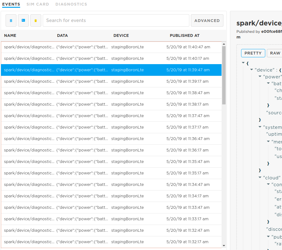
NOTE: Diagnostic messages can be viewed in the Console. Select the device in question, and view the messages under the "EVENTS" tab.
Device vitals are sent:
- On handshake (at most every three days, but can be more frequent if waking from some sleep modes)
- Before an OTA firmware flash if last vitals were sent more than 5 minutes ago
- Under user control from device firmware when using
Particle.publishVitals() - From the cloud side (API or console) when requested
The actual device vitals are communicated to the cloud in a concise binary CoAP payload. The large JSON event you see in the event stream is a synthetic event. It looks like it's coming from the device but that format is not transmitted over the network connection.
It is not possible to disable the device vitals messages, however they do not count as a data operation.
Particle.connect()
Particle.connect() connects the device to the Cloud. This will automatically activate the network connection and attempt to connect to the Particle cloud if the device is not already connected to the cloud.
void setup() {}

void loop() {
  if (Particle.connected() == false) {
    Particle.connect();
  }
}
In most cases, you do not need to call Particle.connect(); it is called automatically when the device boots. Typically you only need to call Particle.connect() when you change the system mode to SEMI_AUTOMATIC (or MANUAL).
Connecting to the cloud does not use Data Operation from your monthly or yearly quota. However, for cellular devices it does use cellular data, so unnecessary connection and disconnection can lead to increased data usage, which could result in hitting the monthly data limit for your account.
On Gen 3 devices (Argon, Boron, B-Series SoM, and Tracker), prior to Device OS 2.0.0, you needed to call WiFi.on() or Cellular.on() before calling Particle.connect(). This is not necessary on Gen 2 devices (any Device OS version) or with 2.0.0 and later.
Normally, Device OS automatically handles connecting to the network and cloud and retrying as necessary.
If you manually add a timeout, for example to put the device to sleep to conserve battery when it cannot connect to cellular, you should do so with care.
- Even though a cellular connection can occur in as little as 10 seconds with LTE Cat 1, it can take significantly longer, especially with 3G and 2G. A minimum of 120 seconds is recommended for this reason.
- You must also stay awake trying to connect for at least 5 minutes periodically. The SIM may switch between IMSI when failing to connect, and if you do not try for long enough, it may not cycle through them properly, causing the device to stay stuck on one that can't be used in your location.
- After 10 minutes of failing to connect, Device OS will do a full shutdown of the cellular modem and restart it. This can help clear issues in some cases. It is recommended that you wait at least 11 minutes to be sure this can occur.
- If you do not want to wait 11 minutes for battery life reasons, you should implement a variable backoff scheme were you at least do this periodically, say once every several hours, to be sure it will be done eventually. This will also assure that the 5 minute IMSI cycling time requirement is met.
- The 11 minute shutdown of the cellular modem consists of sending it command to full reset, and also removing the power to the modem. This is more thorough than entering sleep mode, or using the reset button on the device.
Particle.connectionInterface()
Since 5.6.0:
Returns the current interface used for the Particle cloud connection in Device OS 5.6.0 and later.
// PROTOTYPE
spark::NetworkClass& connectionInterface();

// EXAMPLE
if (Particle.connectionInterface() == WiFi) {
    // WiFi
} else if (Particle.connectionInterface() == Cellular) {
    // Cellular
} else if (Particle.connectionInterface() == Network) {
    // Generic
}
Particle.disconnect()
Particle.disconnect() disconnects the device from the Cloud.
SerialLogHandler logHandler;
int counter = 10000;

void doConnectedWork() {
  digitalWrite(D7, HIGH);
  Log.info("Working online");
}

void doOfflineWork() {
  digitalWrite(D7, LOW);
  Log.info("Working offline");
}

bool needConnection() {
  --counter;
  if (0 == counter)
    counter = 10000;
  return (2000 > counter);
}

void setup() {
  pinMode(D7, OUTPUT);
}

void loop() {
  if (needConnection()) {
    if (!Particle.connected())
      Particle.connect();
    doConnectedWork();
  } else {
    if (Particle.connected())
      Particle.disconnect();
    doOfflineWork();
  }
}
Since 2.0.0:
When disconnecting from the Cloud, by default, the system does not wait for any pending messages, such as cloud events, to be actually sent to acknowledged by the Cloud. This behavior can be changed either globally via Particle.setDisconnectOptions() or by passing an options object to Particle.disconnect(). The timeout parameter controls how long the system can wait for the pending messages to be acknowledged by the Cloud.
// EXAMPLE - disconnecting from the Cloud gracefully
Particle.disconnect(CloudDisconnectOptions().graceful(true).timeout(5000));

// EXAMPLE - using chrono literals to specify a timeout
Particle.disconnect(CloudDisconnectOptions().graceful(true).timeout(5s));
Note that the actual disconnection happens asynchronously. If necessary, waitUntil(Particle.disconnected) can be used to wait until the device has disconnected from the Cloud.
While this function will disconnect from the Cloud, it will keep the connection to the network. If you would like to completely deactivate the network module, use WiFi.off() or Cellular.off() as appropriate.
*NOTE: When the device is disconnected, many features are not possible, including over-the-air updates, reading Particle.variables, and calling Particle.functions.
If you disconnect from the Cloud, you will NOT BE ABLE to flash new firmware over the air. Safe mode can be used to reconnect to the cloud.
Since 5.6.0:
Automatic connection management occurs on the next connection following a disconnection from the Particle cloud. This happens automatically if the underlying network (cellular, Wi-Fi, or ethernet) becomes unavailable.
In some special cases you can manually disconnect to force automatic connection management. You should avoid doing this frequently as the device will not have cloud connectivity during the disconnection, discovery, and reconnection process. It will also use cellular data (but not data operations).
// EXAMPLE
Particle.disconnect();
waitFor(Particle.disconnected, 10000);
Particle.connect();
Clear session
When your device connects to the Particle cloud, if often can do so by resuming the previous session. This dramatically reduces the amount of data used, from around 5-6 Kbytes of data for a full handshake to hundreds of bytes of data for a resume. While a full session handshake does not use data operations, if done excessively it can impact the total data usage on cellular devices. Sessions are automatically renegotiated every 3 days for security reasons.
Under normal circumstances you will never have to manually invalidate the current session. However, if you have a need to do so, this is the best way:
auto opts = CloudDisconnectOptions().clearSession(true);
Particle.disconnect(opts);
You may see references to spark/device/session/end in the community forums, however that method should not be used and may be deprecated in the future. The clearSession flag should be used instead.
Particle.connected()
Returns true when connected to the Cloud, and false when disconnected from the Cloud.
// SYNTAX
Particle.connected();


// EXAMPLE USAGE
SerialLogHandler logHandler;

void setup() {
}

void loop() {
  if (Particle.connected()) {
    Log.info("Connected!");
  }
  delay(1000);
}
This call is fast and can be called frequently without performance degradation.
Particle.disconnected()
Returns true when disconnected from the Cloud, and false when connected to Cloud.
Particle.setDisconnectOptions()
Since 2.0.0:
// EXAMPLE
Particle.setDisconnectOptions(CloudDisconnectOptions().graceful(true).timeout(5000));

// EXAMPLE
Particle.setDisconnectOptions(CloudDisconnectOptions().graceful(true).timeout(5s));
Sets the options for when disconnecting from the cloud, such as from Particle.disconnect(). The default is to abruptly disconnect, however, you can use graceful disconnect mode to make sure pending events have been sent and the cloud notified that a disconnect is about to occur. Since this could take some time if there is poor cellular connectivity, a timeout can also be provided in milliseconds or using chrono literals. This setting will be used for future disconnects until the system is reset.
Note: This method sets the disconnection options globally, meaning that any method that causes the device to disconnect from the Cloud, such as System.reset(), will do so gracefully.
Particle.keepAlive()
On all Gen 3 devices (Argon, Boron, B-Series SoM, Tracker) and Gen 2 cellular devices:
Sets the duration between keep-alive messages used to maintain the connection to the cloud.
// SYNTAX
Particle.keepAlive(23 * 60);    // send a ping every 23 minutes
A keep-alive is used to implement "UDP hole punching" which helps maintain the connection from the cloud to the device. A temporary port-forwarded back-channel is set up by the network to allow packets to be sent from the cloud to the device. As this is a finite resource, unused back-channels are periodically deleted by the network.
Should a device becomes unreachable from the cloud (such as a timed out function call or variable get), one possible cause of this is that the keep alives have not been sent often enough.
The keep-alive for cellular devices duration varies by mobile network operator. The default keep-alive is set to 23 minutes, which is sufficient to maintain the connection on Particle SIM cards. 3rd party SIM cards will need to determine the appropriate keep alive value, typically ranging from 30 seconds to several minutes.
Note: Each keep alive ping consumes 122 bytes of data (61 bytes sent, 61 bytes received).
For Ethernet, you will probably want to set a keepAlive to 25 seconds, like the Argon. In some cases, it could be raised to 2 to 5 minutes; this is dependent on how quickly the Internet router at the site releases port-forwarded back-channel.
For the Argon, the keep-alive is not generally needed. However, in unusual networking situations if the network router/firewall removes the port forwarded back-channels unusually aggressively, you may need to use a keep-alive.
Keep-alives do not use Data Operations from your monthly or yearly quota. However, for cellular devices they do use cellular data, so setting it to a very small value can cause increased data usage, which could result in hitting the monthly data limit for your account.
| Device | Default Keep-Alive |
|---|---|
| All Cellular | 23 minutes |
| Argon (< 3.0.0) | 30 seconds |
| Argon (≥ 3.0.0) | 25 seconds |
Since 1.5.0:
You can also specify a value using chrono literals, for example: Particle.keepAlive(2min) for 2 minutes.
Particle.process()
Using
SYSTEM_THREAD(ENABLED)is recommended for most applications. When using threading mode you generally do not need to useParticle.process(). With Device OS 6.2.0 and later, system thread is always enabled. For additional information, see non-threaded system mode.If you are using
SYSTEM_MODE(AUTOMATIC)(the default if you do not specify), orSEMI_AUTOMATICyou generally do not need toParticle.process()unless your code blocks and prevents loop from returning and does not usedelay()in any inner blocking loop. In other words, if you blockloop()from returning you must call eitherdelay()orParticle.process()within your blocking inner loop.If you are using
SYSTEM_MODE(MANUAL)you must callParticle.process()frequently, preferably on any call toloop()as well as any locations where you are blocking withinloop().
Particle.process() checks for the incoming messages from the Cloud,
and processes any messages that have come in. It also sends keep-alive pings to the Cloud,
so if it's not called frequently, the connection to the Cloud may be lost.
It will also update the ApplicationWatchdog timer using ApplicationWatchdog::checkin().
Particle.syncTime()
Synchronize the time with the Particle Device Cloud. This happens automatically when the device connects to the Cloud. However, if your device runs continuously for a long time, you may want to synchronize once per day or so.
#define ONE_DAY_MILLIS (24 * 60 * 60 * 1000)
unsigned long lastSync = millis();

void loop() {
  if (millis() - lastSync > ONE_DAY_MILLIS) {
    // Request time synchronization from the Particle Device Cloud
    Particle.syncTime();
    lastSync = millis();
  }
}
Note that this function sends a request message to the Cloud and then returns.
The time on the device will not be synchronized until some milliseconds later
when the Cloud responds with the current time between calls to your loop.
See Particle.syncTimeDone(), Particle.timeSyncedLast(), Time.isValid() and Particle.syncTimePending() for information on how to wait for request to be finished.
Synchronizing time does not consume Data Operations from your monthly or yearly quota. However, for cellular devices they do use cellular data, so unnecessary time synchronization can lead to increased data usage, which could result in hitting the monthly data limit for your account.
For more information about real-time clocks on Particle devices, see Learn more about real-time clocks.
Particle.syncTimeDone()
Since 0.6.1:
Returns true if there is no syncTime() request currently pending or there is no active connection to Particle Device Cloud. Returns false when there is a pending syncTime() request.
// SYNTAX
Particle.syncTimeDone();


// EXAMPLE
SerialLogHandler logHandler;

void loop()
{
  // Request time synchronization from the Particle Device Cloud
  Particle.syncTime();
  // Wait until the device receives time from Particle Device Cloud (or connection to Particle Device Cloud is lost)
  waitUntil(Particle.syncTimeDone);
  // Print current time
  Log.info("Current time: %s", Time.timeStr().c_str());
}
See also Particle.timeSyncedLast() and Time.isValid().
Particle.syncTimePending()
Since 0.6.1:
Returns true if there a syncTime() request currently pending. Returns false when there is no syncTime() request pending or there is no active connection to Particle Device Cloud.
// PROTOTYPE
bool syncTimePending(void)
See also Particle.timeSyncedLast() and Time.isValid().
Particle.timeSyncedLast()
// EXAMPLE
SerialLogHandler logHandler;

#define ONE_DAY_MILLIS (24 * 60 * 60 * 1000)

void loop() {
  time_t lastSyncTimestamp;
  unsigned long lastSync = Particle.timeSyncedLast(lastSyncTimestamp);
  if (millis() - lastSync > ONE_DAY_MILLIS) {
    unsigned long cur = millis();
    Log.info("Time was last synchronized %lu milliseconds ago", millis() - lastSync);
    if (lastSyncTimestamp > 0)
    {
      Log.info("Time received from Particle Device Cloud was: ", Time.timeStr(lastSyncTimestamp).c_str());
    }
    // Request time synchronization from Particle Device Cloud
    Particle.syncTime();
    // Wait until the device receives time from Particle Device Cloud (or connection to Particle Device Cloud is lost)
    waitUntil(Particle.syncTimeDone);
    // Check if synchronized successfully
    if (Particle.timeSyncedLast() >= cur)
    {
      // Print current time
      Log.info("Current time: %s", Time.timeStr().c_str());
    }
  }
}
Since 0.6.1:
Used to check when time was last synchronized with Particle Device Cloud.
// PROTOTYPES
system_tick_t timeSyncedLast(void);
system_tick_t timeSyncedLast(time_t& tm);
Returns the number of milliseconds since the device began running the current program when last time synchronization with Particle Device Cloud was performed.
This function takes one optional argument:
timestamp:time_tvariable that will contain a UNIX timestamp received from Particle Device Cloud during last time synchronization
It is possible that the call will block for an indeterminate amount of time, possibly for as long as 10 minutes. This can occur if the system thread is busy trying to reconnect to cellular and is unable to do so. Doing operations that access the cellular modem or require access to the system thread (as is the case for Particle.timeSyncedLast()) from a separate worker thread is a good workaround.
Get public IP
Using this feature, the device can programmatically know its own public IP address.
SYSTEM_THREAD(ENABLED);

SerialLogHandler logHandler;
bool nameRequested = false;

// Open a serial terminal and see the IP address printed out
void subscriptionHandler(const char *topic, const char *data)
{
    Log.info("topic=%s data=%s", topic, data);
}

void setup()
{
    Particle.subscribe("particle/device/ip", subscriptionHandler);
}

void loop() {
    if (Particle.connected() && !nameRequested) {
        nameRequested = true;
        Particle.publish("particle/device/ip");
    }
}
Requesting the public IP uses two data operations, one for the request and one for the response.
Get device name
This gives you the device name that is stored in the cloud.
SYSTEM_THREAD(ENABLED);

SerialLogHandler logHandler;
bool nameRequested = false;

// Open a serial terminal and see the IP address printed out
void subscriptionHandler(const char *topic, const char *data)
{
    Log.info("topic=%s data=%s", topic, data);
}

void setup()
{
    Particle.subscribe("particle/device/name", subscriptionHandler);
}

void loop() {
    if (Particle.connected() && !nameRequested) {
        nameRequested = true;
        Particle.publish("particle/device/name");
    }
}
Instead of fetching the name from the cloud each time, you can fetch it and store it in retained memory or EEPROM. The DeviceNameHelperRK library makes this easy. The link includes instructions and the library is available in Particle Workbench by using Particle: Install Library or in the Web IDE by searching for DeviceNameHelperRK.
Requesting the device name uses two data operations, one for the request and one for the response.
Get random seed
Grab 40 bytes of randomness from the cloud and {e}n{c}r{y}p{t} away!
LogHandler logHandler;

void handler(const char *topic, const char *data) {
    Log.info("topic=%s data=%s", topic, data);
}

void setup() {
    Serial.begin(115200);
    Particle.subscribe("particle/device/random", handler);
    Particle.publish("particle/device/random");
}
Requesting a random seed uses two data operations, one for the request and one for the response.
Publish
Publish an event through the Particle Device Cloud. This can trigger a webhook to an external service, a Logic block to perform operations in the cloud, or another device using Particle.subscribe().
This feature allows the device to generate an event based on a condition. For example, you could connect a motion sensor to the device and have the device generate an event whenever motion is detected.
Limits - Publish
Each event contains:
- An event name (1-64 ASCII characters)
- Event data (optional)
- A timestamp (generated in the cloud)
- Device ID (identifies the publisher of the event)
The size and contents of the event data vary depending on the version of Device OS running on the device.
| Device OS Version | Gen | Size Limit | Binary Data |
|---|---|---|---|
| > 6.3.0 | Gen 3 & 4 | 16384 bytes1 | Allowed |
| > 6.2.0 | Gen 3 & 4 | 1024 bytes | Allowed |
| 3.x - 6.1.x | Gen 3 & 4 | 1024 UTF-8 characters | |
| 3.x | Gen 2 | 864 UTF-8 characters | |
| 0.8.0 - 2.x | Gen 2 & 3 | 622 UTF-8 characters | |
| < 0.8.0 | All | 255 UTF-8 characters |
- 1 Large event data and high publishing rate require using the CloudEvent API.
Typed publish - Publish
Since 6.2.0:
In Device OS 6.2 and later, typed publish is supported. This allows the Content-Type of the publish data to be specified, and allows for binary data payloads. The following types are supported:
| Content Type Constant | MIME Type | Value |
|---|---|---|
ContentType::TEXT |
text/plain; charset=utf-8 |
0 |
ContentType::JPEG |
image/jpeg |
22 |
ContentType::PNG |
image/png |
23 |
ContentType::BINARY |
application/octet-stream |
42 |
ContentType::STRUCTURED |
65001 |
Additionally, JSON (text/json) structured data is supported. This is encoded using an EventData object,
which is a Variant. The Variant can be created from a JSON text string, or built programmatically
by adding fields.
Particle.publish - CloudEvent - Publish
Since 6.3.0:
Particle.publish publishes an event from a device. This can be received by zero or more subscribers, including:
- External services using a webhook
- A Logic block to perform operations in the cloud
- Another device using
Particle.subscribe() - The server-sent events (SSE) data stream
// PROTOTYPE
bool publish(particle::CloudEvent event);
This variation is available in Device OS 6.3.0 and later and is the recommended syntax. The CloudEvent class
is both a container for the event name, event data, and content type, but also maintains the process in
publishing and any error that occurs while publishing.
Note that this overload is always asynchronous and does not use a Future as the other overloads below.
For more information and examples, see the typed and extended publish page.
Particle.publish - Publish
Since 6.2.0:
Particle.publish publishes an event from a device. This can be received by zero or more subscribers, including:
- External services using a webhook
- A Logic block to perform operations in the cloud
- Another device using
Particle.subscribe() - The server-sent events (SSE) data stream
There are a variety of overloads for this function, including:
// PROTOTYPES
particle::Future<bool> publish(const char* name, const char* data, particle::ContentType type, PublishFlags flags = PublishFlags());
particle::Future<bool> publish(const char* name, const String& data, particle::ContentType type, PublishFlags flags = PublishFlags());
particle::Future<bool> publish(const char* name, const char* data, size_t size, particle::ContentType type, PublishFlags flags = PublishFlags());
particle::Future<bool> publish(const char* name, const particle::EventData& data, PublishFlags flags = PublishFlags());
name - Particle.publish - Publish
The name consist 1–64 ASCII characters. Only use letters, numbers, underscores, dashes and slashes in event names. Spaces and special characters may be escaped by different tools and libraries causing unexpected results.
A device may not publish events beginning with a case-insensitive match for "particle" or "spark". Such events are reserved for officially curated data originating from the Cloud.
data (string) - Particle.publish - Publish
The event data can consist of UTF-8 characters. The length depends on the device and Device OS version, but is typically limited to 1024 bytes.
This can be specified as a const char * (pointer to c-string, null-terminated), or a reference to a String object.
data (pointer and length) - Particle.publish - Publish
In Device OS 6.2 and later, the data can be specified with a pointer and length. This is typically used for binary data, and in particular, data that can contain a null byte. It can be used for text if your data source is not null-terminated.
data (EventData) - Particle.publish - Publish
The EventData overload does not require a ContentType value because it is used for structured data in a Variant and is always
encoded as CBOR over-the-air, and JSON in webhooks and other locations. It can optionally include binary data.
contentType
| Content Type Constant | MIME Type | Value |
|---|---|---|
ContentType::TEXT |
text/plain; charset=utf-8 |
0 |
ContentType::JPEG |
image/jpeg |
22 |
ContentType::PNG |
image/png |
23 |
ContentType::BINARY |
application/octet-stream |
42 |
ContentType::STRUCTURED |
65001 |
The content type provides a hint to the receiver for what the data is. This includes the console, which can render some types of data in the event stream.
Future - Particle.publish - Publish
The return type of the Particle.publish function is particle::Future<bool>. There are three common ways to use this:
// EXAMPLE 1
Particle.publish("myEvent");

// EXAMPLE 2
bool bResult = Particle.publish("myEvent", eventData, WITH_ACK);

// EXAMPLE 3
Future<bool> futureResult = Particle.publish("myEvent");
In Example 1, you do not care about whether the call succeeds or not, and this will not wait for the data to be acknowledged by the cloud.
In Example 2, you can check bResult. If true, the publish was successfully made to the cloud. This will block until the packet is acknowledged by the cloud.
In Example 3, you use the future which decouples the waiting and the getting results. This can be useful if you are using a finite state machine. See Future for more information.
Large event data and high publishing rate require using the CloudEvent API, not the classic API.
Particle.publish (classic API) - Publish
Particle.publish pushes the value out of the device at a time controlled by the device firmware. Particle.variable allows the value to be pulled from the device when requested from the cloud side.
Cloud events have the following properties:
- name (1–64 ASCII characters)
Note: Only use letters, numbers, underscores, dashes and slashes in event names. Spaces and special characters may be escaped by different tools and libraries causing unexpected results.
- optional data. The data has a maximum size of 255 to 1024 bytes of UTF-8 characters; see API Field Limits as the limit varies depending on Device OS version and sometimes the device.
A device may not publish events beginning with a case-insensitive match for "particle" or "spark". Such events are reserved for officially curated data originating from the Cloud.
Calling Particle.publish() when the cloud connection has been turned off will not publish an event. This is indicated by the return success code of false.
If the cloud connection is turned on and trying to connect to the cloud unsuccessfully, Particle.publish() may block for up to 20 seconds (normal conditions) to 10 minutes (unusual conditions). Checking Particle.connected() can before calling Particle.publish() can help prevent this.
String variables must be UTF-8 encoded. You cannot send arbitrary binary data or other character sets like ISO-8859-1. If you need to send binary data you can use a text-based encoding like Base64.
NOTE 1: In Device OS 6.2.x and earlier a device can publish at rate of about 1 event/sec, with bursts of up to 4 allowed in 1 second. Back to back burst of 4 messages will take 4 seconds to recover. For rate limits in Device OS 6.3 and later, see rate limits with extended publish.
NOTE 2: Particle.publish() and the Particle.subscribe() handler(s) share the same buffer. As such, calling Particle.publish() within a Particle.subscribe() handler will overwrite the subscribe buffer, corrupting the data! In these cases, copying the subscribe buffer's content to a separate char buffer prior to calling Particle.publish() is recommended.
NOTE 3: Public events are not supported by the cloud as of August 2020. Specifying PUBLIC or leaving out the publish scope essentially results in a private event.
For non-product devices, events published by a device can be subscribed to:
- By other devices claimed to the same account
- By webhooks for the user the device is claimed to
- By the SSE event stream for the user the device is claimed to
For product devices, events published by a device can be subscribed to:
- By other devices claimed to the same account, if the device is claimed
- By webhooks for the user the device is claimed to, if the device is claimed
- By the SSE event stream for the user the device is claimed to, if the device is claimed
- By product webhooks for the product the device is associated with, whether or not the device is claimed
- By the SSE event stream for the product the device is associated with, whether or not the device is claimed
Public events could previously be received by anyone on the Internet, and anyone could generate events to send to your devices. This did not turn out to a common use-case, and the ease at which you could accidentally use this mode, creating a security hole, caused it to be removed.
Each publish uses one Data Operation from your monthly or yearly quota. This is true for both WITH_ACK and NO_ACK modes.
- Publishes are not end-to-end confirmed. Even if the
Particle.publishreturns true, there is no guarantee that any recipient (another device, webhook, or SSE) will receive it. - It is possible to receive an event more than once. The most common reason is a lost ACK, which will cause the device to send the event again. Storing a unique identifier in the event payload may help code defensively for this possibility.
- It is possible that events will arrive out-of-order. The most common cause is retransmission, but it can also occur because events can flow through different redundant servers, each with slightly difference latency, so it's possible that two event sent rapidly will arrive out-of-order as well. This is common for multi-part webhook responses.
- It is possible that even if
Particle.publishreturns false, the event will still be received by the cloud later. This occurs because the 20-second timeout is reached, so false is returned, but the event is still buffered in Device OS and will be retransmitted if the reconnection to the cloud succeeds.
Large event data and high publishing rate require using the CloudEvent API, not the classic API.
Publish an event with the given name and no data.
// SYNTAX
Particle.publish(const char *eventName, PublishFlags flags);
Particle.publish(String eventName, PublishFlags flags);
Returns:
A bool indicating success: (true or false)
// EXAMPLE USAGE
bool success;
success = Particle.publish("motion-detected");
if (!success) {
  // get here if event publish did not work
}

// EXAMPLE USAGE - This format is no longer necessary
// PRIVATE is the default and only option now
bool success;
success = Particle.publish("motion-detected", PRIVATE);
if (!success) {
  // get here if event publish did not work
}
// PROTOTYPES
particle::Future<bool> publish(const char* name);
particle::Future<bool> publish(const char* name, const char* data);

// EXAMPLE USAGE 1
Particle.publish("temperature", "19");

// EXAMPLE USAGE 2
int temp = 19;
Particle.publish("temperature", String(temp));

// EXAMPLE USAGE 3
float temp = 19.5;
Particle.publish("temperature", String::format("%.1f", temp);
Publish an event with the given name and data.
The data must be a string in the ASCII or UTF-8 character set. If you have an integer or floating point value, you'll need to convert it to a string first.
You cannot publish binary data with Particle.publish. To send binary data, convert it to a string using hex or Base 64 encoding.
While Base85 (Ascii85) provides a more dense encoding than Base64, it is not recommended if you are publishing data to be sent to an external server by a webhook. The Base85 alphabet includes the left curly bracket, and the {{ sequence is recognized as a mustache template delimiter during webhook processing, causing the data to be corrupted. The backslash can also cause unexpected data transformation.
// EXAMPLE - Check if event was queued for publishing successfully
float temp = 19.5;
bool success = Particle.publish("temperature", String::format("%.1f", temp);

// EXAMPLE - Check if event was queued for publishing successfully
float temp = 19.5;
bool success = Particle.publish("temperature", String::format("%.1f", temp);
Normally, you store or test the result of Particle.publish in a bool variable that indicates that the event was queued for publishing successfully, or reached the cloud, when used with WITH_ACK.
But what is the particle::Future<bool> in the prototype above? See the application note AN009 Firmware Examples for how to use a Future to make the otherwise synchronous Particle.publish() call asynchronous.
COMPLEMENTARY API CALL
GET /v1/events/{EVENT_NAME}

# EXAMPLE REQUEST
curl -H "Authorization: Bearer {ACCESS_TOKEN_GOES_HERE}" \
    https://api.particle.io/v1/events/motion-detected

# Will return a stream that echoes text when your event is published
event: motion-detected
data: {"data":"23:23:44","ttl":"60","published_at":"2014-05-28T19:20:34.638Z","deviceid":"0123456789abcdef"}
Cellular Devices (B-Series SoM, Tracker SoM, Tracker One, Boron, E404X, E-Series, and Electron):
// PROTOTYPES
particle::Future<bool> publish(const char* name, PublishFlags flags1, PublishFlags flags2 = PublishFlags());
particle::Future<bool> publish(const char* name, const char* data, PublishFlags flags1, PublishFlags flags2 = PublishFlags());

// SYNTAX

float temperature = sensor.readTemperature();  // by way of example, not part of the API
Particle.publish("t", String::format("%.2f",temperature), NO_ACK);  // make sure to convert to const char * or String
On Gen 2 cellular devices (Electron, E-Series) and all Gen 3 devices (Argon, Boron, B-Series SoM, Tracker SoM, E404X):
NO_ACK flag
Unless specified otherwise, events sent to the cloud are sent as a reliable message. The device waits for acknowledgement from the cloud that the event has been received, resending the event in the background up to 3 times before giving up.
The NO_ACK flag disables this acknowledge/retry behavior and sends the event only once. This reduces data consumption per event, with the possibility that the event may not reach the cloud.
For example, the NO_ACK flag could be useful when many events are sent (such as sensor readings) and the occasional lost event can be tolerated.
// SYNTAX
bool success = Particle.publish("motion-detected", NULL, WITH_ACK);

// No longer necessary, PRIVATE is always used even when not specified
bool success = Particle.publish("motion-detected", NULL, PRIVATE, WITH_ACK);
WITH_ACK flag
Since 0.6.1:
This flag causes Particle.publish() to return only after receiving an acknowledgement that the published event has been received by the Cloud.
If you do not use WITH_ACK then the request is still acknowledged internally, and retransmission attempted up to 3 times, but Particle.publish() will return more quickly.
Since 0.7.0:
// EXAMPLE - combining Particle.publish() flags
// No longer necessary, PRIVATE is always used even when not specified
Particle.publish("motion-detected", PRIVATE | WITH_ACK);
Particle.publish() flags can be combined using a regular syntax with OR operator (|).
For products, it's possible receive product events sent by devices using webhooks or the Server-Sent-Events (SSE) data stream.
// SYNTAX - DEPRECATED
Particle.publish(const char *eventName, const char *data, int ttl, PublishFlags flags);
Particle.publish(String eventName, String data, int ttl, PublishFlags flags);
Previously, there were overloads with a ttl (time-to-live) value. These have been deprecated as the ttl has never been supported by the Particle cloud. All events expire immediately if not subscribed to or exported from the Particle cloud using a webhook, integration like Google cloud, or the server-sent-events (SSE) stream.
Even if you use NO_ACK mode and do not check the result code from Particle.publish() it is possible that the call will still block for an indeterminate amount of time, possibly for as long as 10 minutes. This can occur if you publish while in the process of attempting to reconnect to the network. At a minimum, you should make sure that Particle.connected() returns true before publishing. Doing publish operations from a separate worker thread is another option.
CloudEvent
Since 6.3.0:
The CloudEvent class is available in Device OS 6.3.0 and later and is the recommended way to handle
publish and subscribe. It is both a container for the event name, event data, and content type, but also maintains the process in
publishing and any error that occurs while publishing.
You typically store a CloudEvent object as a global variable or class member variable. You should not allocate a
CloudEvent as a non-static local variable within a function because it not only holds the data, but it is also
used to convey whether the publish succeeded or not. The Particle.publish() overload that takes a CloudEvent is asynchronous
and returns before the publish has completed. The CloudEvent must remain allocated until the publish is actually complete,
by success or failure.
For more information and examples, see the typed and extended publish page.
Getting and settings - CloudEvent
name - CloudEvent
Sets the event name. The name is copied by the setter.
// PROTOTYPE - setter
CloudEvent& name(const char* name)

// PROTOTYPE - getter
const char* name() const;
The name consist 1–64 ASCII characters. Only use letters, numbers, underscores, dashes and slashes in event names. Spaces and special characters may be escaped by different tools and libraries causing unexpected results.
A device may not publish events beginning with a case-insensitive match for "particle" or "spark". Such events are reserved for officially curated data originating from the Cloud.
contentType - CloudEvent
Set or get the content type for the event.
// PROTOTYPE - setter
CloudEvent& contentType(ContentType type)

// PROTOTYPE - getter
ContentType contentType() const
| Content Type Constant | MIME Type | Value |
|---|---|---|
ContentType::TEXT |
text/plain; charset=utf-8 |
0 |
ContentType::JPEG |
image/jpeg |
22 |
ContentType::PNG |
image/png |
23 |
ContentType::BINARY |
application/octet-stream |
42 |
ContentType::STRUCTURED |
65001 |
When publishing you typically set the value, but you can also get the value that was previously set.
When subscribing to an event, you typically get the value to see what the publisher of the event has set.
You don't typically set the content type to STRUCTURED; when you set the data from a Variant this is handled automatically for you.
data - from c-string - CloudEvent
Copies data from a c-string (null terminated string) into the event data.
Typically used with the TEXT content type. The data cannot contain a null byte at a location other than the
end of a string so this is not suitable for binary data.
// PROTOTYPE
CloudEvent& data(const char* data)
data - from pointer and length - CloudEvent
Copies data from a buffer specified with pointer and length. This is useful if the data source is not null-terminated.
This can be used with binary data, though you will typically use the overload that also includes the ContentType instead.
// PROTOTYPE
CloudEvent& data(const char* data, size_t size);
data - from pointer and length with content type - CloudEvent
Copies data from a buffer specified with pointer and length. This is typically used with binary data.
See Content-Type, above, for the valid values.
// PROTOTYPE
CloudEvent& data(const char* data, size_t size, ContentType type)
data - from String - CloudEvent
Copies data from a String object.
// PROTOTYPE
CloudEvent& data(const String& data)
dataString - CloudEvent
Returns a copy of the data as a String. This is typically used for text data.
// PROTOTYPE
String dataString() const
data from Buffer - CloudEvent
Copies binary data from a Buffer object. This is an alternative to using a pointer and length.
// PROTOTYPE
CloudEvent& data(const Buffer& data)
data - to Buffer - CloudEvent
Returns a copy of the data in the CloudEvent as a Buffer object. This is typically used for binary data.
// PROTOTYPE
Buffer data() const
data - from EventData - CloudEvent
Copies data from an EventData object, which is a Variant. This is used for structured data.
// PROTOTYPE
CloudEvent& data(const EventData& data)
data - to EventData - CloudEvent
Returns a copy of the structured data in the CloudEvent as an EventData object, which is a Variant.
// PROTOTYPE
EventData dataStructured() const
For more information, see structured subscription in the typed and extended publish page.
File read and write - CloudEvent
Event data can be saved to a file and restored from a file easily. For more information about the file system, see File system and File system API.
loadData - CloudEvent
Loads the data in a CloudEvent from a file. Note that this only loads the data, not the other parameters like name, content-type, etc.
Returns 0 on success or a non-zero system error code.
// PROTOTYPE
CloudEvent& loadData(const char* path)
saveData - CloudEvent
Saves the data in a CloudEvent to a file. Note that this only saves the data, not the other parameters like name, content-type, etc.
Returns 0 on success or a non-zero system error code.
// PROTOTYPE
int saveData(const char* path)
Utility methods - CloudEvent
setSize - CloudEvent
Set the size of the data. This is rarely needed.
// PROTOTYPE
int setSize(size_t size)
size - CloudEvent
Get the size of the data. This is the encoded size is stored internally so this is efficient.
You may want to use this with canPublish to see if the event can be published based on the current rate limiting.
// PROTOTYPE
size_t size() const
isEmpty - CloudEvent
Returns true if the event is empty (has no data).
// PROTOTYPE
bool isEmpty() const
Stream methods - CloudEvent
The CloudEvent class implements the Stream interface which can be helpful if you want to
read or write the event data as a stream of bytes.
seek - CloudEvent
Seek to a position relative to the start of the data (0 = first byte).
// PROTOTYPE
int seek(size_t pos)
pos - CloudEvent
Returns the current position in the data.
// PROTOTYPE
size_t pos() const
write - CloudEvent
Write a byte or bytes to the data at the current position.
// PROTOTYPES
size_t write(uint8_t b) override
size_t write(const uint8_t* data, size_t size) override
int write(const char* data)
int write(const char* data, size_t size)
read - CloudEvent
Read a byte or bytes from the data at the current position.
// PROTOTYPES
int read() override
int read(char* data, size_t size)
readBytes - CloudEvent
Read a bytes from the data at the current position.
// PROTOTYPE
size_t readBytes(char* data, size_t size) override
peek - CloudEvent
Read a byte or bytes from the data at the current position but do not move the current position so the next read will read the same bytes.
// PROTOTYPES
int peek() override
int peek(char* data, size_t size)
available - CloudEvent
Returns the number of bytes that are available to read. Returns 0 if there are no bytes available to read or the event is in an invalid state for reading.
// PROTOTYPE
int available() override
flush - CloudEvent
It is not necessary to call flush when you are finished writing, as the writes are never buffered. This method is a no-op.
// PROTOTYPE
void flush() override
Publish status - CloudEvent
status - CloudEvent
| Constant | Description | Accessibility |
|---|---|---|
Status::NEW |
Initial status of a newly created or received event | Reading and writing |
Status::SENDING |
The event is being sent to the cloud | Reading |
Status::SENT |
The event was successfully sent to the cloud | Reading and writing |
Status::FAILED |
Recoverable error occurred while creating the event or sending it to the cloud | Reading and writing |
Status::INVALID |
Irrecoverable error occurred while creating the event. | Not accessible |
Status::FAILED indicates a recoverable error. The failed operation with the event can be retried when the condition that caused the error is resolved.
For Status::FAILED and Status::INVALID the error() method can be used to find more information about the reason.
isNew - CloudEvent
Shorthand for event.status() == CloudEvent::NEW. This is the initial status of a newly created or received event
// PROTOTYPE
bool isNew() const
isSending - CloudEvent
Shorthand for event.status() == CloudEvent::SENDING. The event is being sent to the cloud.
// PROTOTYPE
bool isSending() const
isSent - CloudEvent
Shorthand for event.status() == CloudEvent::SENT. The event was successfully sent to the cloud.
// PROTOTYPE
bool isSent() const
isOk - CloudEvent
Returns true if the event status is something other than Status::FAILED or Status::INVALID.
// PROTOTYPE
bool isOk() const
isValid - CloudEvent
Returns true if the event status is not Status::INVALID. Note that this is different than isOk().
// PROTOTYPE
bool isValid() const
error - CloudEvent
Returns a 0 if the event is not in a failed or invalid state, otherwise a system error code defined Error::Type, which is a negative value.
// PROTOTYPE
int error() const;
See system errors for the available error codes.
cancel - CloudEvent
Cancel sending the event.
This method has no effect if the event is not currently being sent to the Cloud.
A cancelled event is invalidated and cannot be published again.
// PROTOTYPE
void cancel();
resetStatus - CloudEvent
Reset the status of the event.
This method resets the status of the event back to NEW if the current status is SENT or FAILED. Otherwise, it has no effect.
It is normally not necessary to call this method before publishing a failed event again.
// PROTOTYPE
void resetStatus();
clear - CloudEvent
Clear and reinitialize the event instance.
// PROTOTYPE
void clear();

// EXAMPLE
// These two statements are equivalent
event.clear();
event = CloudEvent();
onStatusChange - CloudEvent
Set a callback to be invoked when the status of the event changes.
For an example, see Simple publish callback.
// PROTOTYPE
CloudEvent& onStatusChange(std::function<OnStatusChange> callback);

// Handler definition
typedef void OnStatusChange(CloudEvent event);

// Handler prototype
void myStatusChangeHandler(CloudEvent event)
canPublish - CloudEvent
Check if an event with a given size would be within the limit for the amount of event data in flight once it's attempted to be published.
- size Size of the event data.
- Returns
trueif the event can be published, otherwisefalse.
For an example, see State machine class publish.
// PROTOTYPE
static bool canPublish(size_t size);
Subscribe
Subscribe to events published by devices.
This allows devices to talk to each other very easily. For example, one device could publish events when a motion sensor is triggered and another could subscribe to these events and respond by sounding an alarm.
You typically call Particle.subscribe() once for each subscription during setup().
A subscription works like a prefix filter. If you subscribe to "foo", you will receive any event whose name begins with "foo", including "foo", "fool", "foobar", and "food/indian/sweet-curry-beans". The maximum length of the subscribe prefix is 64 characters.
You should not call Particle.subscribe() from the constructor of a globally allocated C++ object. See Global Object Constructors for more information.
Each event delivery attempt to a subscription handler uses one Data Operation from your monthly or yearly quota. Setting up the subscription does not use a Data Operations. You should take advantage of the event prefix to avoid delivering events that you do not need. If poor connectivity results in multiple attempts, it could result in multiple Data Operations, up to 3. If the device is currently marked as offline, then no attempt will be made and no Data Operations will be incurred.
If you have multiple devices that subscribe to a hook-response but only want to monitor the response to their own request, as opposed to any device in the account sharing the webhook, you should include the Device ID in the custom hook response as described here. This will assure that you will not consume Data Operations for webhooks intended for other devices.
Particle.subscribe(System.deviceID() + "/hook-response/weather/", myHandler);
- It is possible to receive an event more than once. The most common reason is a lost ACK, which will cause the device to send the event again. Storing a unique identifier in the event payload may help code defensively for this possibility.
- It is possible that events will arrive out-of-order. The most common cause is retransmission, but it can also occur because events can flow through different redundant servers, each with slightly difference latency, so it's possible that two event sent rapidly will arrive out-of-order as well. This is common for multi-part webhook responses.
Subscribe (with content type) - Subscribe
Since 6.2.0:
// PROTOTYPES
bool subscribe(const char* name, particle::EventHandlerWithContentType handler);
bool subscribe(const char* name, particle::EventHandlerWithContentTypeFn handler);

typedef void (*EventHandlerWithContentType)(const char* name, const char* data, size_t size, ContentType type);
typedef std::function<void(const char* name, const char* data, size_t size, ContentType type)> EventHandlerWithContentTypeFn;

// EventHandlerWithContentType handler function prototype
void myHandler(const char* name, const char* data, size_t size, ContentType type)

// EventHandler function prototype (classic API)
void myHandler(const char *event_name, const char *data)
The new API passes both a data and a size allowing it to be used with data that contains null bytes,
including binary data. The ContentType is also passed to the handler for the handler to use as desired.
Subscribe (CloudEvent) - Subscribe
Since 6.3.0:
// PROTOTYPES
bool subscribe(const char* name, particle::EventHandlerWithCloudEvent* handler,
        const particle::SubscribeOptions& opts = particle::SubscribeOptions());
bool subscribe(const char* name, std::function<particle::EventHandlerWithCloudEvent> handler,
        const particle::SubscribeOptions& opts = particle::SubscribeOptions());

// Cloud event subscription handler prototype
void mySubscriptionHandler(CloudEvent event);

// EventHandlerWithCloudEvent
typedef void (EventHandlerWithCloudEvent)(CloudEvent event);
For more information and examples, see the typed and extended publish page.
SubscribeOptions - Subscribe
Since 6.3.0:
The SubscribeOptions class specifies options when subscribing to events using a CloudEvent.
structured - SubscribeOptions - Subscribe
Enable or disable encoding of event data in a structured data format.
This option instructs the Cloud to encode all events sent to the device for this subscription in a compact structured data format.
The exact format used is implementation-specific. The application is expected to parse the data in this format using the methods of the CloudEvent class, such as dataStructured().
By default, this option is disabled.
// PROTOTYPE - setter
SubscribeOptions& structured(bool enabled)

// PROTOTYPE - getter
bool structured() const;
For more information, see structured subscription in the typed and extended publish page.
Subscribe (with Variant) - Subscribe
Since 6.2.0:
If you are expecting structured data, use the subscribe overload that takes a handler with a Variant.
// EXAMPLE
void myHandler(const char* name, Variant data) {
    Log.info("a=%d b=%s", data.get("a").toInt(), data.get("b").toString().c_str());
}

void setup() {
    Particle.subscribe("myEvent", myHandler);
}
If you publish this JSON:
{"a":123,"b":"testing"}
For example, with the Particle CLI:
particle publish myEvent '{"a":123,"b":"testing"}'
The USB serial debug log will show something like:
0000013271 [app] INFO: a=123 b=testing
The prototypes for subscribing to events with a Variant are:
// PROTOTYPES
bool subscribe(const char* name, particle::EventHandlerWithVariant handler);
bool subscribe(const char* name, particle::EventHandlerWithVariantFn handler);

// Handler definitions
typedef void (*EventHandlerWithVariant)(const char* name, EventData data);
typedef std::function<void(const char* name, EventData data)> EventHandlerWithVariantFn;

// EventHandlerWithVariant handler function prototype
void myHandler(const char* name, EventData data);
void myHandler(const char* name, Variant data);

// EventData definition
typedef Variant EventData;
The Variant overload does not have a ContentType because Variant data is always CBOR over-the-air and JSON via webhooks and SSE.
Subscrible (classic API) - Subscribe
SerialLogHandler logHandler;
int i = 0;

void myHandler(const char *event, const char *data)
{
  i++;
  Log.info("%d: event=%s data=%s", i, event, (data ? data : "NULL"));
}

void setup()
{
  Particle.subscribe("temperature", myHandler);
}
To use Particle.subscribe(), define a handler function and register it, typically in setup().
You can register a method in a C++ object as a subscription handler.
#include "Particle.h"

SerialLogHandler logHandler;

class MyClass {
public:
    MyClass();
    virtual ~MyClass();

    void setup();

    void subscriptionHandler(const char *eventName, const char *data);
};

MyClass::MyClass() {
}

MyClass::~MyClass() {
}

void MyClass::setup() {
    Particle.subscribe("myEvent", &MyClass::subscriptionHandler, this);
}

void MyClass::subscriptionHandler(const char *eventName, const char *data) {
    Log.info("eventName=%s data=%s", eventName, data);
}

// In this example, MyClass is a globally constructed object.
MyClass myClass;

void setup() {
    myClass.setup();
}

void loop() {

}
You should not call Particle.subscribe() from the constructor of a globally allocated C++ object. See Global Object Constructors for more information.
Each event delivery attempt to a subscription handler uses one Data Operation from your monthly or yearly quota. Setting up the subscription does not use a Data Operations. You should take advantage of the event prefix to avoid delivering events that you do not need. If poor connectivity results in multiple attempts, it could result in multiple Data Operations, up to 3. If the device is currently marked as offline, then no attempt will be made and no Data Operations will be incurred.
If you have multiple devices that subscribe to a hook-response but only want to monitor the response to their own request, as opposed to any device in the account sharing the webhook, you should include the Device ID in the custom hook response as described here. This will assure that you will not consume Data Operations for webhooks intended for other devices.
Particle.subscribe(System.deviceID() + "/hook-response/weather/", myHandler, MY_DEVICES);
A subscription works like a prefix filter. If you subscribe to "foo", you will receive any event whose name begins with "foo", including "foo", "fool", "foobar", and "food/indian/sweet-curry-beans". The maximum length of the subscribe prefix is 64 characters.
Received events will be passed to a handler function similar to Particle.function().
A subscription handler (like myHandler above) must return void and take two arguments, both of which are C strings (const char *).
- The first argument is the full name of the published event.
- The second argument (which may be NULL) is any data that came along with the event.
Particle.subscribe() returns a bool indicating success. It is OK to register a subscription when
the device is not connected to the cloud - the subscription is automatically registered
with the cloud next time the device connects.
See special webhook events for more details about handling multipart responses from a webhook in your subscription handler.
A device can register up to 4 event handlers. This means you can call
Particle.subscribe()a maximum of 4 times; after that it will returnfalse. On some versions of Device OS on some devices the limit may be higher.Particle.publish()and theParticle.subscribe()handler(s) share the same buffer. As such, callingParticle.publish()within aParticle.subscribe()handler will overwrite the subscribe buffer, corrupting the data! In these cases, copying the subscribe buffer's content to a separate char buffer prior to callingParticle.publish()is recommended.You can call Particle.subscribe from setup() or from loop(). The subscription list can be added to at any time, and more than once. The subscriptions are only updated once loop is running, however. During setup() the subscription will not yet be active. Very old versions of Device OS (prior to 1.0.0) may behave differently.
// PROTOTYPES
bool subscribe(const char* name, EventHandler handler);
bool subscribe(const char* name, wiring_event_handler_t handler);

template<typename T>
bool subscribe(const char* name, void (T::*handler)(const char*, const char*), T* instance);

// Handler definitions
typedef void (*EventHandler)(const char *event_name, const char *data);
typedef std::function<void (const char*, const char*)> wiring_event_handler_t;

// Handler function prototype
void eventHandler(const char *event_name, const char *data)
Prior to August 2020, you could subscribe to the public event stream using ALL_DEVICES. This is no longer possible as the public event stream no longer exists. Likewise, MY_DEVICES is no longer necessary as that is the only option now.
// This syntax is no longer necessary
Particle.subscribe("the_event_prefix", theHandler, MY_DEVICES);
Particle.subscribe("the_event_prefix", theHandler, ALL_DEVICES);
- Unclaimed devices can only be used in a product.
- Unclaimed devices can send product events.
- Unclaimed devices can receive function calls and variable requests from the product.
- Unclaimed devices can receive events using Particle.subscribe as of March 2023. This was not previously possible.
The behavior of unclaimed product devices with respect to subscribing to events changed in March 2023:
- Prior to March 2023, claiming was required if the device firmware subscribed to events on-device. This is no longer necessary.
- You still need to claim a device is if you are using a webhook in the sandbox of the user who claimed the device. It is recommended that you use product webhooks instead, which do not require claiming.
- If you are using a device with Mark as Development device, you may want to claim the device to your account so you can easily OTA flash it from Particle Workbench or other development environments.
- If you previously had firmware that subscribed to events but was the device was unclaimed, the events previously disappeared. This is no longer the case and the device will now start receiving those events, and each event will count as a data operation.
- Claiming is still allowed, if you prefer to continue to use claiming, but not recommended.
Additionally:
- Publishes are not end-to-end confirmed. Even if the
Particle.publishreturns true, there is no guarantee that any recipient (another device, webhook, or SSE) will receive it. - It is possible to receive an event more than once. The most common reason is a lost ACK, which will cause the device to send the event again. Storing a unique identifier in the event payload may help code defensively for this possibility.
- It is possible that events will arrive out-of-order. The most common cause is retransmission, but it can also occur because events can flow through different redundant servers, each with slightly difference latency, so it's possible that two event sent rapidly will arrive out-of-order as well. This is common for multi-part webhook responses.
- It is possible that even if
Particle.publishreturns false, the event will still be received by the cloud later. This occurs because the 20-second timeout is reached, so false is returned, but the event is still buffered in Device OS and will be retransmitted if the reconnection to the cloud succeeds.
Future
The Future class is used by Particle.publish to optionally block, and to optionally obtain the success or failure result later.
// EXAMPLE PROTOTYPE
particle::Future<bool> publish(const char* name);

// EXAMPLE USAGE 1
Particle.publish("myEvent");

// EXAMPLE USAGE 2
bool result = Particle.publish("myEvent");
In example usage 1, the value is not checked, and the call will be asynchronous.
In example usage 2, the value is stored in a bool, and the call will block until completion or timeout.
// Future methods
bool isDone() const;
ResultT result() const;
operator ResultT() const;
It is possible to store the Future<bool> in a variable. This allows the operation to proceed asynchronously, then
check later to see if the is operation has completed (isDone()) and what the underlying result was (result()).
This is useful if you've implemented your code as finite state machine and you want to not block, transition to
the next state, and wait in that state until completion. You'd then transition to another state depending
on whether you succeeded or failed.
Note that you may still want to do publishes from a worker thread instead of the main loop, because the Particle.publish function can still block in some cases if there is no network connectivity. For an example, see the background-publish library. This is used by Tracker Edge and Monitor Edge firmware for location publishes.
Ethernet
Note:
Ethernet is available on the Photon 2, Argon, Boron when used with the Ethernet FeatherWing or with the B-Series SoM with the evaluation board or the equivalent circuitry on your base board. Circuitry can be added to your P2 or E404X base board for Ethernet as well.
On the P2, Photon 2, and M-SoM it is highly recommended that you use Device OS 5.9.0 or later when using Ethernet due to important bugs that were fixed in 5.6.0 and 5.7.0 that can affect Ethernet usability on RTL872x devices.
It is not available on Gen 2 devices (Photon, P1, Electron, and E-Series except the E404X).
For more information about Ethernet, see the application note AN037 Ethernet.
By default, Ethernet detection is not done because it will toggle GPIO that may affect circuits that are not using Ethernet. When you select Ethernet during device setup, it is enabled and the setting stored in configuration flash.
It's also possible to enable Ethernet detection from code. This is saved in configuration flash so you don't need to call it every time.
You should call it from setup() but make sure you are using SYSTEM_THREAD(ENABLED) so it can be enabled before the connecting to the cloud. You should not call it from STARTUP().
SYSTEM_THREAD(ENABLED);

void setup()
{
  System.enableFeature(FEATURE_ETHERNET_DETECTION);
}
Prior to Device OS 5.9.0, interrupt (nINTERRUPT) and reset (nRESET) pins were required to use Ethernet. With Device OS 5.9.0 you can operate without these connected.
If you are using the Adafruit Ethernet Feather Wing (instead of the Particle Feather Wing), by default nRESET and nINTERRUPT pins are not connected. You will either need to connect them (on the small header on the short side) to pins D3 and D4 with jumper wires, or use Device OS 5.9.0 and operate without these two hardware control pins.
| Device | SPI MISO | SPI MOSI | SPI SCK | Chip Select | Reset | Interrupt |
|---|---|---|---|---|---|---|
| Particle Ethernet | MISO | MOSI | SCK | D5 | D3 | D4 |
| Adafruit Ethernet | MISO | MOSI | SCK | D5 | 1 | 1 |
| B-SoM eval board | MISO | MOSI | SCK | D8 | A7 | D22 |
| M.2 SoM breakout board | MISO | MOSI | SCK | D8 | A7 | D22 |
| Muon | MISO | MOSI | SCK | A3 | NC | A4 |
| Tracker SoM | MISO | MOSI | SCK | D2 | D6 | D7 |
1On the Adafruit Ethernet FeatherWing this pin is not connected by default.
Pin configuration - Ethernet
Since 5.3.0:
In Device OS 5.3.0, it is possible to reconfigure the pins that are used for Ethernet control signals CS, RESET, and INT. This may be desirable if you need to use pins D3-D5 for other purposes, such as SPI1.
In Device OS 5.9.0 and later, it's possible to configure RESET and INT as PIN_INVALID, meaning you are not using hardware reset and interrupt.
Not using an interrupt pin will use poling and will reduce performance.
The CS pin is always required.
The correct order of operations is:
Start with
FEATURE_ETHERNET_DETECTIONdisabled this will prevent probing the default GPIO that you are using for other purposes, which may have unintended consequences.It is recommended that you enable threading and SEMI_AUTOMATIC mode because you will need to execute code before connecting to the cloud.
SYSTEM_THREAD(ENABLED);
SYSTEM_MODE(SEMI_AUTOMATIC);
- If
Ethernet.isOn()is false (it's off), then remap the pins. This setting is persistent on reset, cold boot, application firmware flash, and Device OS upgrade. It also is used when in safe mode so Device OS can be upgraded OTA over Ethernet.
if_wiznet_pin_remap remap = {};
remap.base.type = IF_WIZNET_DRIVER_SPECIFIC_PIN_REMAP;
remap.cs_pin = A0;
remap.reset_pin = A2;
remap.int_pin = A1;

auto ret = if_request(nullptr, IF_REQ_DRIVER_SPECIFIC, &remap, sizeof(remap), nullptr);
// ret is SYSTEM_ERROR_NONE on success
- After successful reconfiguration, enable ethernet detection with System.enableFeature(FEATURE_ETHERNET_DETECTION), and then reset the device with System.reset(). This will be fast because the device did not connect to the cloud the first time. This setting is persistent on reset, cold boot, application firmware flash, and Device OS upgrade. It also is used when in safe mode so Device OS can be upgraded OTA over Ethernet.
System.enableFeature(FEATURE_ETHERNET_DETECTION);
System.reset();
Reset to defaults - Ethernet pin remapping
In Device OS 6.1.1 and earlier, if you wanted to restore a pin to its default value, you could set it to PIN_INVALID. This is no
longer possible as PIN_INVALID is now a usable value for the int_pin for operation without a hardware interrupt pin.
You must set it back to the actual default pin to restore default pin mapping.
The following code will reset the pin remapping to the default values:
if_wiznet_pin_remap remap = {};
remap.base.type = IF_WIZNET_DRIVER_SPECIFIC_PIN_REMAP;
remap.cs_pin = HAL_PLATFORM_ETHERNET_WIZNETIF_CS_PIN_DEFAULT;
remap.reset_pin = HAL_PLATFORM_ETHERNET_WIZNETIF_RESET_PIN_DEFAULT;
remap.int_pin = HAL_PLATFORM_ETHERNET_WIZNETIF_INT_PIN_DEFAULT;

if_request(nullptr, IF_REQ_DRIVER_SPECIFIC, &remap, sizeof(remap), nullptr);
Sample application - Ethernet pin remapping
Here's a full sample application for testing:
// SAMPLE APPLICATION
#include "Particle.h"
SYSTEM_THREAD(ENABLED);
SYSTEM_MODE(SEMI_AUTOMATIC);
Serial1LogHandler log1Handler(115200, LOG_LEVEL_ALL);

retained uint8_t resetRetry = 0;

void setup() {
#if HAL_PLATFORM_WIFI && !HAL_PLATFORM_WIFI_SCAN_ONLY
    // To force Ethernet only, clear Wi-Fi credentials
    Log.info("Clear Wi-Fi credentionals...");
    WiFi.clearCredentials();
#endif // HAL_PLATFORM_WIFI && !HAL_PLATFORM_WIFI_SCAN_ONLY

    // Disable Listening Mode if not required
    if (System.featureEnabled(FEATURE_DISABLE_LISTENING_MODE)) {
        Log.info("FEATURE_DISABLE_LISTENING_MODE enabled");
    } else {
        Log.info("Disabling Listening Mode...");
        System.enableFeature(FEATURE_DISABLE_LISTENING_MODE);
    }

    Log.info("Checking if Ethernet is on...");
    if (Ethernet.isOn()) {
        Log.info("Ethernet is on");
        uint8_t macAddrBuf[8] = {};
        uint8_t* macAddr = Ethernet.macAddress(macAddrBuf);
        if (macAddr != nullptr) {
            Log.info("Ethernet MAC: %02x %02x %02x %02x %02x %02x",
                    macAddr[0], macAddr[1], macAddr[2], macAddr[3], macAddr[4], macAddr[5]);
        }
        Ethernet.connect();
        waitFor(Ethernet.ready, 30000);
        Log.info("Ethernet.ready: %d", Ethernet.ready());
        resetRetry = 0;
    } else if (++resetRetry <= 3) {
        Log.info("Ethernet is off or not detected, attmpting to remap pins: %d/3", resetRetry);

        if_wiznet_pin_remap remap = {};
        remap.base.type = IF_WIZNET_DRIVER_SPECIFIC_PIN_REMAP;

        remap.cs_pin = D10;
        remap.reset_pin = D6;
        remap.int_pin = D7;

        auto ret = if_request(nullptr, IF_REQ_DRIVER_SPECIFIC, &remap, sizeof(remap), nullptr);
        if (ret != SYSTEM_ERROR_NONE) {
            Log.error("Ethernet GPIO config error: %d", ret);
        } else {
            if (System.featureEnabled(FEATURE_ETHERNET_DETECTION)) {
                Log.info("FEATURE_ETHERNET_DETECTION enabled");
            } else {
                Log.info("Enabling Ethernet...");
                System.enableFeature(FEATURE_ETHERNET_DETECTION);
            }
            delay(500);
            System.reset();
        }
    }

    Particle.connect();
}

void loop() {
    static system_tick_t lastPublish = millis();
    static int count = 0;
    static bool reconnect = false;

    if (Particle.connected()) {
        reconnect = false;
        if (millis() - lastPublish >= 10000UL) {
            Particle.publish("mytest", String(++count), PRIVATE, WITH_ACK);
            lastPublish = millis();
        }
    }

    // Detect a network dropout and reconnect quickly
    if (!reconnect && !Ethernet.ready()) {
        Log.info("Particle disconnect...");
        Particle.disconnect();
        waitFor(Particle.disconnected, 5000);
        Log.info("Network disconnect...");
        Network.disconnect();
        Particle.connect();
        reconnect = true;
    }
}
Muon Ethernet configuration
The following code can be used to enable Ethernet on the Muon. This only needs to be done once and the device must be reset after configuration for the changes to take effect.
This is done automatically by setup.particle.io, but this technique can be used if manually setting up devices, or setting up a fleet.
// Enable 3V3_AUX
SystemPowerConfiguration powerConfig = System.getPowerConfiguration();
powerConfig.auxiliaryPowerControlPin(D7).interruptPin(A7);
System.setPowerConfiguration(powerConfig);

// Enable Ethernet
if_wiznet_pin_remap remap = {};
remap.base.type = IF_WIZNET_DRIVER_SPECIFIC_PIN_REMAP;

System.enableFeature(FEATURE_ETHERNET_DETECTION);
remap.cs_pin = A3;
remap.reset_pin = PIN_INVALID;
remap.int_pin = A4;
auto ret = if_request(nullptr, IF_REQ_DRIVER_SPECIFIC, &remap, sizeof(remap), nullptr);
M.2 SoM Breakout board Ethernet configuration
The following code can be used to enable Ethernet on the M.2 SoM breakout board. This only needs to be done once and the device must be reset after configuration for the changes to take effect.
This is done automatically by setup.particle.io, but this technique can be used if manually setting up devices, or setting up a fleet.
// Enable 3V3_AUX
SystemPowerConfiguration powerConfig = System.getPowerConfiguration();
powerConfig.auxiliaryPowerControlPin(D23).interruptPin(A6);
System.setPowerConfiguration(powerConfig);

// Enable Ethernet
if_wiznet_pin_remap remap = {};
remap.base.type = IF_WIZNET_DRIVER_SPECIFIC_PIN_REMAP;

System.enableFeature(FEATURE_ETHERNET_DETECTION);
remap.cs_pin = D5;
remap.reset_pin = PIN_INVALID;
remap.int_pin = PIN_INVALID;
auto ret = if_request(nullptr, IF_REQ_DRIVER_SPECIFIC, &remap, sizeof(remap), nullptr);
on() - Ethernet
Ethernet.on() turns on the Ethernet module. Useful when you've turned it off, and you changed your mind.
Note that Ethernet.on() does not need to be called unless you have changed the system mode or you have previously turned the Ethernet module off.
off() - Ethernet
Ethernet.off() turns off the Ethernet module.
isOn() - Ethernet
Since 2.1.0:
This function will return true if the Ethernet is available, powered on, and went through low level initialization. Otherwise it will return false.
// SYNTAX
Ethernet.isOn();

// EXAMPLE
Ethernet.on();
waitFor(Ethernet.isOn, 30000);
isOff() - Ethernet
Since 2.1.0:
This function will return true if the Ethernet is powered off. Otherwise it will return false.
// SYNTAX
Ethernet.isOff();

// EXAMPLE
Ethernet.off();
waitFor(Ethernet.isOff, 60000);
connect() - Ethernet
Attempts to connect to the Ethernet network. When this function returns, the device may not have an IP address on the LAN; use Ethernet.ready() to determine the connection status.
// SYNTAX
Ethernet.connect();
disconnect() - Ethernet
Disconnects from the Ethernet network, but leaves the Ethernet module on.
// SYNTAX
Ethernet.disconnect();
connecting() - Ethernet
This function will return true once the device is attempting to connect, and will return false once the device has successfully connected to the Ethernet network.
// SYNTAX
Ethernet.connecting();
ready() - Ethernet
This function will return true once the device is connected to the network and has been assigned an IP address, which means that it's ready to open TCP sockets and send UDP datagrams. Otherwise it will return false.
// SYNTAX
Ethernet.ready();
In order for Ethernet to be considered ready the Ethernet link must be up, and IP address assigned, DNS configured, and a gateway set. Thus if you using isolated Ethernet (gateway of 0.0.0.0), you cannot use Ethernet.ready() to determine if it's up. This is because Ethernet.ready() implies that it's ready to be used for the cloud connection, which is not true for isolated LANs. If you want to check for isolated LAN up, you can use !Ethernet.connecting() && Ethernet.localIP() != IPAddress()
setConfig() - Ethernet
Since 5.3.0:
Set a NetworkInterfaceConfig for the Ethernet interface running Device OS 5.3.0 or later. This is used to set a static IP address or restore DHCP addressing (the default).
// PROTOTYPE
int setConfig(const particle::NetworkInterfaceConfig& conf);

// EXAMPLE
Ethernet.setConfig(NetworkInterfaceConfig()
  .source(NetworkInterfaceConfigSource::STATIC)
  .address({192,168,1,20}, {255,255,255,0})
  .gateway(SockAddr({192,168,1,1}))
  .dns(SockAddr({192,168,1,1})));
getConfig() - Ethernet
Since 5.3.0:
Get the current NetworkInterfaceConfig for the Ethernet interface running Device OS 5.3.0 or later.
// PROTOTYPE
particle::NetworkInterfaceConfig getConfig(String profile = String()) const;
prefer() - Ethernet
Since 5.7.0:
You should normally let automatic connection management handle which network interface to use.
In some cases you may want to prefer cellular or Wi-Fi, and this can be done using the API. Note however:
- The automatic connection management rules still apply.
- The preference only determines which to use if multiple interfaces are available. It will not force connection to a non-available interface.
- Setting a preference does not affect an immediate change if the cloud is currently connected. It will only be consulted on the next automatic connection management which typically occurs after the cloud disconnects.
- Only one network type can be preferred, setting
Ethernet.prefer()will clearCellular.prefer()for example.
// PROTOTYPE
virtual NetworkClass& prefer(bool prefer = true);

// EXAMPLE - enable prefer Ethernet
Ethernet.prefer();

// EXAMPLE - disable prefer Ethernet
Ethernet.prefer(false);
isPreferred() - Ethernet
Returns true if the preferred network interface is Ethernet. This only indicates that the interface has been preferred and does not reflect what interface is in use.
// PROTOTYPE
virtual bool isPreferred();

if (Ethernet.isPreferred()) {
    // Do something here
}
ping() - Ethernet
Since 6.3.0:
Ethernet.ping() allows you to ping an IP address and returns the number of packets received as an int or a negative error code.
This is an ICMP ping, not the Particle cloud ping and does not use data operations.
// PROTOTYPES
int ping(IPAddress remoteIP, unsigned nTries = 1, unsigned timeoutMs = DEFAULT_PING_TIMEOUT);
int ping(String hostname, unsigned nTries = 1, unsigned timeoutMs = DEFAULT_PING_TIMEOUT);
int ping(IPAddress remoteIP, std::chrono::milliseconds timeout, unsigned nTries = 1);
int ping(String hostname, std::chrono::milliseconds timeout, unsigned nTries = 1);
When using a hostname, a DNS lookup is done. If the hostname is not found, a negative result code (SYSTEM_ERROR_NOT_FOUND, -150) is returned.
The DEFAULT_PING_TIMEOUT is 4000 milliseconds (4 seconds).
These methods are only avaiable in Device OS 6.3.0 and later. They are available in the WiFi, Cellular, Ethernet, and Network classes.
listen() - Ethernet
This will enter or exit listening mode, which opens a Serial connection to get Ethernet credentials over USB, and also listens for credentials over Bluetooth.
// SYNTAX - enter listening mode
Ethernet.listen();
Listening mode blocks application code. Advanced cases that use multithreading, interrupts, or system events have the ability to continue to execute application code while in listening mode, and may wish to then exit listening mode, such as after a timeout. Listening mode is stopped using this syntax:
// SYNTAX - exit listening mode
Ethernet.listen(false);
listening() - Ethernet
// SYNTAX
Ethernet.listening();
Returns true if the device is in listening mode (blinking dark blue).
This is only relevant when using SYSTEM_THREAD(ENABLED). When not using threading, listening mode stops
user firmware from running, so you would not have an opportunity to test the value and calling this always
returns false. With Device OS 6.2.0 and later, system thread is always enabled.
setListenTimeout() - Ethernet
// SYNTAX
Ethernet.setListenTimeout(seconds);
Ethernet.setListenTimeout(seconds) is used to set a timeout value for Listening Mode. Values are specified in seconds, and 0 disables the timeout. By default, Ethernet devices do not have any timeout set (seconds=0). As long as interrupts are enabled, a timer is started and running while the device is in listening mode (Ethernet.listening()==true). After the timer expires, listening mode will be exited automatically. If Ethernet.setListenTimeout() is called while the timer is currently in progress, the timer will be updated and restarted with the new value (e.g. updating from 10 seconds to 30 seconds, or 10 seconds to 0 seconds (disabled)).
Note: Enabling multi-threaded mode with SYSTEM_THREAD(ENABLED) will allow user code to update the timeout value while Listening Mode is active.
Since 1.5.0:
You can also specify a value using chrono literals, for example: Ethernet.setListenTimeout(5min) for 5 minutes.
getListenTimeout() - Ethernet
// SYNTAX
uint16_t seconds = Ethernet.getListenTimeout();
Ethernet.getListenTimeout() is used to get the timeout value currently set for Listening Mode. Values are returned in (uint16_t)seconds, and 0 indicates the timeout is disabled. By default, Ethernet devices do not have any timeout set (seconds=0).
macAddress() - Ethernet
Ethernet.macAddress() gets the MAC address of the Ethernet interface.
// EXAMPLE
SerialLogHandler logHandler;

void setup() {
  // Wait for a USB serial connection for up to 30 seconds
  waitFor(Serial.isConnected, 30000);

  uint8_t addr[6];
  Ethernet.macAddress(addr);

  Log.info("mac: %02x-%02x-%02x-%02x-%02x-%02x", addr[0], addr[1], addr[2], addr[3], addr[4], addr[5]);
}
localIP() - Ethernet
Ethernet.localIP() is used to get the IP address of the Ethernet interface as an IPAddress.
// EXAMPLE
SerialLogHandler logHandler;

void setup() {
  // Wait for a USB serial connection for up to 30 seconds
  waitFor(Serial.isConnected, 30000);

  Log.info("localIP: %s", Ethernet.localIP().toString().c_str());
}
subnetMask() - Ethernet
Ethernet.subnetMask() returns the subnet mask of the network as an IPAddress.
SerialLogHandler logHandler;

void setup() {
 // Wait for a USB serial connection for up to 30 seconds
  waitFor(Serial.isConnected, 30000);

  // Prints out the subnet mask over Serial.
  Log.info(Ethernet.subnetMask());
}
gatewayIP() - Ethernet
Ethernet.gatewayIP() returns the gateway IP address of the network as an IPAddress.
SerialLogHandler logHandler;

void setup() {
  Serial.begin(9600);
  // Wait for a USB serial connection for up to 30 seconds
  waitFor(Serial.isConnected, 30000);

  // Prints out the gateway IP over Serial.
  Log.info(Ethernet.gatewayIP());
}
dnsServerIP() - Ethernet
Ethernet.dnsServerIP() retrieves the IP address of the DNS server that resolves
DNS requests for the device's network connection. This will often be 0.0.0.0.
dhcpServerIP() - Ethernet
Ethernet.dhcpServerIP() retrieves the IP address of the DHCP server that manages
the IP address used by the device's network connection. This often will be 0.0.0.0.
WiFi
Wi-Fi Devices (P2, Photon 2, Argon, P1, Photon):
The WiFi class is available on the P2, Photon 2, Argon, Photon, and P1.
The WiFi class is not available on cellular devices such as the Boron and
B-Series SoM (Gen 3) or Electron and E-Series (Gen 2).
While the Tracker SoM has a Wi-Fi module for geolocation, it cannot be used for network
connectivity and thus it does not have the WiFi class.
on()
WiFi.on() turns on the Wi-Fi module. Useful when you've turned it off, and you changed your mind.
Note that WiFi.on() does not need to be called unless you have changed the system mode or you have previously turned the Wi-Fi module off.
off()
// EXAMPLE:
Particle.disconnect();
WiFi.off();
WiFi.off() turns off the Wi-Fi module. Useful for saving power, since most of the power draw of the device is the Wi-Fi module.
You must call Particle.disconnect() before turning off the Wi-Fi manually, otherwise the cloud connection may turn it back on again.
This should only be used with SYSTEM_MODE(SEMI_AUTOMATIC) (or MANUAL) as the cloud connection and Wi-Fi are managed by Device OS in AUTOMATIC mode.
connect()
Attempts to connect to the Wi-Fi network. If there are no credentials stored, this will enter listening mode (see below for how to avoid this.). If there are credentials stored, this will try the available credentials until connection is successful. When this function returns, the device may not have an IP address on the LAN; use WiFi.ready() to determine the connection status.
// SYNTAX
WiFi.connect();
Since 0.4.5:
It's possible to call WiFi.connect() without entering listening mode in the case where no credentials are stored:
// SYNTAX
WiFi.connect(WIFI_CONNECT_SKIP_LISTEN);
If there are no credentials then the call does nothing other than turn on the Wi-Fi module.
On Gen 3 devices (Argon, Boron, B-Series SoM, and Tracker), prior to Device OS 2.0.0, you needed to call WiFi.on() or Cellular.on() before calling Particle.connect(). This is not necessary on Gen 2 devices (any Device OS version) or with 2.0.0 and later.
On the Argon, starting with Device OS 1.5.0, a quick Wi-Fi scan is done before connecting. The list of available networks is compared with the configured SSIDs. The access point with the strongest signal is connected to. Prior to 1.5.0, only the original access point BSSID that was configured would ever be connected to, even if there was a different access point on the same SSID and network with a stronger signal.
disconnect()
Disconnects from the Wi-Fi network, but leaves the Wi-Fi module on.
// SYNTAX
WiFi.disconnect();
connecting()
This function will return true once the device is attempting to connect using stored Wi-Fi credentials, and will return false once the device has successfully connected to the Wi-Fi network.
// SYNTAX
WiFi.connecting();
ready()
This function will return true once the device is connected to the network and has been assigned an IP address, which means that it's ready to open TCP sockets and send UDP datagrams. Otherwise it will return false.
// SYNTAX
WiFi.ready();
setConfig() [WiFi]
Since 5.3.0:
Set a NetworkInterfaceConfig for the Wi-Fi interface on the Argon, P2, and Photon 2 running Device OS 5.3.0 or later. This is used to set a static IP address or restore DHCP addressing (the default).
// PROTOTYPE
int setConfig(const particle::NetworkInterfaceConfig& conf);

// EXAMPLE
WiFi.setConfig(NetworkInterfaceConfig()
  .source(NetworkInterfaceConfigSource::STATIC)
  .address({192,168,1,20}, {255,255,255,0})
  .gateway({192,168,1,1})
  .dns({192,168,1,1});
getConfig() [WiFi]
Since 5.3.0:
Get the current NetworkInterfaceConfig for the Wi-Fi interface on the Argon, P2, and Photon 2 running Device OS 5.3.0 or later.
// PROTOTYPE
particle::NetworkInterfaceConfig getConfig(String profile = String()) const;
selectAntenna() [antenna]
Note:
On ths P2, Photon 2, and M-SoM this is only supported on Device OS 5.3.2 and later.
The Argon (Gen 3) does not have an antenna switch for Wi-Fi; it can only use an external antenna. There is a separate setting for the Argon BLE antenna (BLE.selectAntenna).
On the Photon and P1 (Gen 2), selectAntenna selects which antenna the device should connect to Wi-Fi with and remembers that setting until it is changed. Resetting Wi-Fi credentials does not clear the antenna setting.
// SYNTAX
STARTUP(WiFi.selectAntenna(ANT_INTERNAL)); // selects the CHIP antenna
STARTUP(WiFi.selectAntenna(ANT_EXTERNAL)); // selects the u.FL antenna
STARTUP(WiFi.selectAntenna(ANT_AUTO)); // continually switches at high speed between antennas
WiFi.selectAntenna() selects one of three antenna modes. It takes one argument: ANT_AUTO, ANT_INTERNAL or ANT_EXTERNAL.
Note that the antenna selection is remembered even after power off or when entering safe mode. This is to allow your device to be configured once and then continue to function with the selected antenna when applications are flashed that don't specify which antenna to use. Resetting Wi-Fi credentials (long press of MODE) does not clear the antenna selection.
You may specify in code which antenna to use as the default at boot time using the STARTUP() macro. If you are using system thread enabled mode or SEMI_AUTOMATIC or MANUAL system mode, you can select the antenna on setup or loop, however you should not set it continuously.
If no antenna has been previously selected, the ANT_INTERNAL antenna will be chosen by default.
WiFi.selectAntenna() returns 0 on success, or a non-zero error code.
// Use the STARTUP() macro to set the default antenna
// to use system boot time.
// In this case it would be set to the chip antenna
STARTUP(WiFi.selectAntenna(ANT_INTERNAL));

void setup() {
  // your setup code
}

void loop() {
  // your loop code
}
getAntenna()
Note:
On ths P2, Photon 2, and M-SoM this is only supported on Device OS 5.3.2 and later.
// PROTOTYPE
WLanSelectAntenna_TypeDef getAntenna()
This function returns the currently selected antenna, one of:
ANT_AUTOANT_INTERNALANT_EXTERNAL
prefer() [WiFi]
Since 5.7.0:
You should normally let automatic connection management handle which network interface to use.
In some cases you may want to prefer cellular or Wi-Fi, and this can be done using the API. Note however:
- The automatic connection management rules still apply.
- The preference only determines which to use if multiple interfaces are available. It will not force connection to a non-available interface.
- Setting a preference does not affect an immediate change if the cloud is currently connected. It will only be consulted on the next automatic connection management which typically occurs after the cloud disconnects.
- Only one network type can be preferred, setting
WiFi.prefer()will clearCellular.prefer()for example.
// PROTOTYPE
virtual NetworkClass& prefer(bool prefer = true);

// EXAMPLE - enable prefer Wi-Fi
WiFi.prefer();

// EXAMPLE - disable prefer Wi-Fi
WiFi.prefer(false);
isPreferred() [WiFi]
Returns true if the preferred network interface is Wi-Fi. This only indicates that the interface has been preferred and does not reflect what interface is in use.
// PROTOTYPE
virtual bool isPreferred();

if (WiFi.isPreferred()) {
    // Do something here
}
listen()
This will enter or exit listening mode, which opens a Serial connection to get Wi-Fi credentials over USB, and also listens for credentials over Soft AP on the Photon or BLE on the Argon.
// SYNTAX - enter listening mode
WiFi.listen();
Listening mode blocks application code. Advanced cases that use multithreading, interrupts, or system events have the ability to continue to execute application code while in listening mode, and may wish to then exit listening mode, such as after a timeout. Listening mode is stopped using this syntax:
// SYNTAX - exit listening mode
WiFi.listen(false);
listening()
// SYNTAX
WiFi.listening();
Returns true if the device is in listening mode (blinking dark blue).
This is only relevant when using SYSTEM_THREAD(ENABLED). When not using threading, listening mode stops
user firmware from running, so you would not have an opportunity to test the value and calling this always
returns false. With Device OS 6.2.0 and later, system thread is always enabled.
setListenTimeout()
Since 0.6.1:
// SYNTAX
WiFi.setListenTimeout(seconds);
WiFi.setListenTimeout(seconds) is used to set a timeout value for Listening Mode. Values are specified in seconds, and 0 disables the timeout. By default, Wi-Fi devices do not have any timeout set (seconds=0). As long as interrupts are enabled, a timer is started and running while the device is in listening mode (WiFi.listening()==true). After the timer expires, listening mode will be exited automatically. If WiFi.setListenTimeout() is called while the timer is currently in progress, the timer will be updated and restarted with the new value (e.g. updating from 10 seconds to 30 seconds, or 10 seconds to 0 seconds (disabled)). Note: Enabling multi-threaded mode with SYSTEM_THREAD(ENABLED) will allow user code to update the timeout value while Listening Mode is active.
// EXAMPLE
// If desired, use the STARTUP() macro to set the timeout value at boot time.
STARTUP(WiFi.setListenTimeout(60)); // set listening mode timeout to 60 seconds

void setup() {
  // your setup code
}

void loop() {
  // update the timeout later in code based on an expression
  if (disableTimeout) WiFi.setListenTimeout(0); // disables the listening mode timeout
}
Since 1.5.0:
You can also specify a value using chrono literals, for example: WiFi.setListenTimeout(5min) for 5 minutes.
getListenTimeout()
Since 0.6.1:
// SYNTAX
uint16_t seconds = WiFi.getListenTimeout();
WiFi.getListenTimeout() is used to get the timeout value currently set for Listening Mode. Values are returned in (uint16_t)seconds, and 0 indicates the timeout is disabled. By default, Wi-Fi devices do not have any timeout set (seconds=0).
setCredentials()
Allows the application to set credentials for the Wi-Fi network from within the code. These credentials will be added to the device's memory, and the device will automatically attempt to connect to this network in the future.
- The P2, Photon 2, and Argon remember the 10 most recently set credentials.
- The P2, Photon 2, and M-SoM do not currently support WPA Enterprise.
- The Argon does not support WPA Enterprise.
- The Photon and P1 remember the 5 most recently set credentials.
- The Photon and P1 can store one set of WPA Enterprise credentials in Device OS 0.7.0 and later.
// Connects to an unsecured network.
WiFi.setCredentials(ssid);
WiFi.setCredentials("My_Router_Is_Big");

// Connects to a network secured with WPA2 credentials.
WiFi.setCredentials(ssid, password);
WiFi.setCredentials("My_Router", "mypasswordishuge");

// Connects to a network with a specified authentication procedure.
// Options are WPA2, WPA, or WEP.
WiFi.setCredentials(ssid, password, auth);
WiFi.setCredentials("My_Router", "wepistheworst", WEP);
When used with hidden or offline networks, the security cipher is also required. This is only supported on the Photon and P1. The Argon, P2, and Photon 2 do not support connecting to hidden networks.
// for hidden and offline networks on the Photon, the security cipher is also needed
// Cipher options are WLAN_CIPHER_AES, WLAN_CIPHER_TKIP and WLAN_CIPHER_AES_TKIP
WiFi.setCredentials(ssid, password, auth, cipher);
WiFi.setCredentials("SSID", "PASSWORD", WPA2, WLAN_CIPHER_AES);
// Connects to a network with an authentication procedure specified by WiFiCredentials object
WiFi.setCredentials(credentials);
WiFiCredentials credentials;
credentials.setSsid("My_Router")
           .setSecurity(WEP)
           .setPassword("wepistheworst");
WiFi.setCredentials(credentials);
The password is limited to 64 7-bit ASCII characters. If you pass in a longer password, only the first 64 characters will be saved.
Since 0.7.0:
Note:
WPA Enterprise is only supported on the Photon and P1.
It is not supported on the Argon, P2, and Photon 2.
Credentials can be set using WiFiCredentials class.
For information on setting up WPA2 Enterprise from the Particle CLI, see this article.
// WPA2 Enterprise with EAP-TLS

// We are setting WPA2 Enterprise credentials
WiFiCredentials credentials("My_Enterprise_AP", WPA2_ENTERPRISE);
// EAP type: EAP-TLS
credentials.setEapType(WLAN_EAP_TYPE_TLS);
// Client certificate in PEM format
credentials.setClientCertificate("-----BEGIN CERTIFICATE-----\r\n" \
                                 /* ... */ \
                                 "-----END CERTIFICATE-----\r\n\r\n"
                                );
// Private key in PEM format
credentials.setPrivateKey("-----BEGIN RSA PRIVATE KEY-----\r\n" \
                          /* ... */ \
                          "-----END RSA PRIVATE KEY-----\r\n\r\n"
                         );
// Root (CA) certificate in PEM format (optional)
credentials.setRootCertificate("-----BEGIN CERTIFICATE-----\r\n" \
                               /* ... */ \
                               "-----END CERTIFICATE-----\r\n\r\n"
                              );
// EAP outer identity (optional, default - "anonymous")
credentials.setOuterIdentity("anonymous");
// Save credentials
WiFi.setCredentials(credentials);
// WPA Enterprise with PEAP/MSCHAPv2

// We are setting WPA Enterprise credentials
WiFiCredentials credentials("My_Enterprise_AP", WPA_ENTERPRISE);
// EAP type: PEAP/MSCHAPv2
credentials.setEapType(WLAN_EAP_TYPE_PEAP);
// Set username
credentials.setIdentity("username");
// Set password
credentials.setPassword("password");
// Set outer identity (optional, default - "anonymous")
credentials.setOuterIdentity("anonymous");
// Root (CA) certificate in PEM format (optional)
credentials.setRootCertificate("-----BEGIN CERTIFICATE-----\r\n" \
                               /* ... */ \
                               "-----END CERTIFICATE-----\r\n\r\n"
                              );
// Save credentials
WiFi.setCredentials(credentials);
Parameters:
ssid: SSID (string)password: password (string)auth: see SecurityType enum.cipher: see WLanSecurityCipher enum.credentials: an instance of WiFiCredentials class.
This function returns true if credentials were successfully saved, or false in case of an error.
Note: Setting WPA/WPA2 Enterprise credentials requires use of WiFiCredentials class.
Note: In order for WiFi.setCredentials() to work, the Wi-Fi module needs to be on (if switched off or disabled via non_AUTOMATIC SYSTEM_MODEs call WiFi.on()).
getCredentials()
Since 0.4.9:
Lists the Wi-Fi networks with credentials stored on the device. Returns the number of stored networks.
Note that this returns details about the Wi-Fi networks, but not the actual password.
// DEFINITION
typedef struct WiFiAccessPoint {
   size_t size;
   char ssid[33];
   uint8_t ssidLength;
   uint8_t bssid[6];
   WLanSecurityType security;
   WLanSecurityCipher cipher;
   uint8_t channel;
   int maxDataRate;
   int rssi;
} WiFiAccessPoint;

// EXAMPLE
LogHandler logHandler;

WiFiAccessPoint ap[5];
int found = WiFi.getCredentials(ap, 5);
for (int i = 0; i < found; i++) {
    Log.info("ssid: %s", ap[i].ssid);
    // security is one of WLAN_SEC_UNSEC, WLAN_SEC_WEP, WLAN_SEC_WPA, WLAN_SEC_WPA2, WLAN_SEC_WPA_ENTERPRISE, WLAN_SEC_WPA2_ENTERPRISE
    Log.info("security: %d", (int) ap[i].security);
    // cipher is one of WLAN_CIPHER_AES, WLAN_CIPHER_TKIP or WLAN_CIPHER_AES_TKIP
    Log.info("cipher: %d", (int) ap[i].cipher);
}
clearCredentials()
This will clear all saved credentials from the Wi-Fi module's memory. This will return true on success and false if the Wi-Fi module has an error.
// SYNTAX
WiFi.clearCredentials();
hasCredentials()
Will return true if there are Wi-Fi credentials stored in the Wi-Fi module's memory.
// SYNTAX
WiFi.hasCredentials();
macAddress()
WiFi.macAddress() returns the MAC address of the device.
// EXAMPLE USAGE
SerialLogHandler logHandler;
byte mac[6];

void setup() {
  WiFi.on();
  // wait up to 10 seconds for USB host to connect
  // requires firmware >= 0.5.3
  waitFor(Serial.isConnected, 10000);

  WiFi.macAddress(mac);

  Log.info("mac: %02x:%02x:%02x:%02x:%02x:%02x", mac[0], mac[1], mac[2], mac[3], mac[4], mac[5]);
}
SSID()
WiFi.SSID() returns the SSID of the network the device is currently connected to as a char*.
BSSID()
WiFi.BSSID() retrieves the 6-byte MAC address of the access point the device is currently connected to.
SerialLogHandler logHandler;
byte bssid[6];

void setup() {
  Serial.begin(9600);
  // Wait for a USB serial connection for up to 30 seconds
  waitFor(Serial.isConnected, 30000);

  WiFi.BSSID(bssid);
  Log.info("%02X:%02X:%02X:%02X:%02X:%02X", bssid[0], bssid[1], bssid[2], bssid[3], bssid[4], bssid[5]);
}
RSSI()
WiFi.RSSI() returns the signal strength of a Wi-Fi network from -127 (weak) to -1dB (strong) as an int. Positive return values indicate an error with 1 indicating a Wi-Fi chip error and 2 indicating a time-out error.
// SYNTAX
int rssi = WiFi.RSSI();
WiFiSignal rssi = WiFi.RSSI();
Since 0.8.0
WiFi.RSSI() returns an instance of WiFiSignal class.
// SYNTAX
WiFiSignal sig = WiFi.RSSI();
If you are passing the RSSI value as a variable argument, such as with Serial.printlnf, Log.info, snprintf, etc. make sure you add a cast:
Log.info("RSSI=%d", (int8_t) WiFi.RSSI()).
This is necessary for the compiler to correctly convert the WiFiSignal class into a number.
WiFiSignal Class
This class allows to query a number of signal parameters of the currently connected WiFi network.
getStrength()
Gets the signal strength as a percentage (0.0 - 100.0). See getStrengthValue() on how strength values are mapped to 0%-100% range.
// SYNTAX
WiFiSignal sig = WiFi.RSSI();
float strength = sig.getStrength();

// EXAMPLE
WiFiSignal sig = WiFi.RSSI();
Log.info("WiFi signal strength: %.02f%%", sig.getStrength());
Returns: float
getQuality()
Gets the signal quality as a percentage (0.0 - 100.0). See getQualityValue() on how quality values are mapped to 0%-100% range.
// SYNTAX
WiFiSignal sig = WiFi.RSSI();
float quality = sig.getQuality();

// EXAMPLE
WiFiSignal sig = WiFi.RSSI();
Log.info("WiFi signal quality: %.02f%%", sig.getQuality());
Returns: float
getStrengthValue()
// SYNTAX
WiFiSignal sig = WiFi.RSSI();
float strength = sig.getStrengthValue();
Gets the raw signal strength value in dBm. Range: [-90, 0].
Returns: float
getQualityValue()
// SYNTAX
WiFiSignal sig = WiFi.RSSI();
float quality = sig.getQualityValue();
Gets the raw signal quality value (SNR) in dB. Range: [0, 90].
Returns: float
ping()
Since 6.3.0:
WiFi.ping() allows you to ping an IP address and returns the number of packets received as an int or a negative error code.
This is an ICMP ping, not the Particle cloud ping and does not use data operations.
// PROTOTYPES
int ping(IPAddress remoteIP, unsigned nTries = 1, unsigned timeoutMs = DEFAULT_PING_TIMEOUT);
int ping(String hostname, unsigned nTries = 1, unsigned timeoutMs = DEFAULT_PING_TIMEOUT);
int ping(IPAddress remoteIP, std::chrono::milliseconds timeout, unsigned nTries = 1);
int ping(String hostname, std::chrono::milliseconds timeout, unsigned nTries = 1);
When using a hostname, a DNS lookup is done. If the hostname is not found, a negative result code (SYSTEM_ERROR_NOT_FOUND, -150) is returned.
The DEFAULT_PING_TIMEOUT is 4000 milliseconds (4 seconds).
These methods are only avaiable in Device OS 6.3.0 and later. They are available in the WiFi, Cellular, Ethernet, and Network classes.
On the Photon 1 and P1, only these methods are available, and only in the WiFi class, but are available on most versions of Device OS for Gen 2.
// PROTOTYPES - Photon 1 and P1 only
int ping(IPAddress remoteIP);
int ping(IPAddress remoteIP, unsigned nTries);
scan()
Returns information about access points within range of the device.
The first form is the simplest, but also least flexible. You provide a
array of WiFiAccessPoint instances, and the call to WiFi.scan() fills out the array.
If there are more APs detected than will fit in the array, they are dropped.
Returns the number of access points written to the array.
// EXAMPLE - retrieve up to 20 Wi-Fi APs
SerialLogHandler logHandler;

WiFiAccessPoint aps[20];
int found = WiFi.scan(aps, 20);
for (int i=0; i<found; i++) {
    WiFiAccessPoint& ap = aps[i];
    Log.info("ssid=%s security=%d channel=%d rssi=%d", ap.ssid, (int)ap.security, (int)ap.channel, ap.rssi);
}
The more advanced call to WiFi.scan() uses a callback function that receives
each scanned access point.
// EXAMPLE using a callback
void wifi_scan_callback(WiFiAccessPoint* wap, void* data)
{
    WiFiAccessPoint& ap = *wap;
    Log.info("ssid=%s security=%d channel=%d rssi=%d", ap.ssid, (int)ap.security, (int)ap.channel, ap.rssi);
}

void loop()
{
    int result_count = WiFi.scan(wifi_scan_callback);
    Log.info("result_count=%d", result_count);
}
The main reason for doing this is that you gain access to all access points available without having to know in advance how many there might be.
You can also pass a 2nd parameter to WiFi.scan() after the callback, which allows
object-oriented code to be used.
// EXAMPLE - class to find the strongest AP

class FindStrongestSSID
{
    char strongest_ssid[33];
    int strongest_rssi;

    // This is the callback passed to WiFi.scan()
    // It makes the call on the `self` instance - to go from a static
    // member function to an instance member function.
    static void handle_ap(WiFiAccessPoint* wap, FindStrongestSSID* self)
    {
        self->next(*wap);
    }

    // determine if this AP is stronger than the strongest seen so far
    void next(WiFiAccessPoint& ap)
    {
        if ((ap.rssi < 0) && (ap.rssi > strongest_rssi)) {
            strongest_rssi = ap.rssi;
            strcpy(strongest_ssid, ap.ssid);
        }
    }

public:

    /**
     * Scan Wi-Fi Access Points and retrieve the strongest one.
     */
    const char* scan()
    {
        // initialize data
        strongest_rssi = -128;
        strongest_ssid[0] = 0;
        // perform the scan
        WiFi.scan(handle_ap, this);
        return strongest_ssid;
    }
};

// Now use the class
FindStrongestSSID strongestFinder;
const char* ssid = strongestFinder.scan();

}
resolve()
WiFi.resolve() finds the IP address for a domain name.
// SYNTAX
ip = WiFi.resolve(name);
Parameters:
name: the domain name to resolve (string)
It returns the IP address if the domain name is found, otherwise a blank IP address.
// EXAMPLE USAGE

IPAddress ip;
void setup() {
   ip = WiFi.resolve("www.google.com");
   if(ip) {
     // IP address was resolved
   } else {
     // name resolution failed
   }
}
localIP()
WiFi.localIP() returns the local IP address assigned to the device as an IPAddress.
SerialLogHandler logHandler;

void setup() {
  // Wait for a USB serial connection for up to 30 seconds
  waitFor(Serial.isConnected, 30000);

  // Prints out the local IP over Serial.
  Log.info("ip address: %s", WiFi.localIP().toString().c_str());
}
subnetMask()
WiFi.subnetMask() returns the subnet mask of the network as an IPAddress.
SerialLogHandler logHandler;

void setup() {
  // Wait for a USB serial connection for up to 30 seconds
  waitFor(Serial.isConnected, 30000);

  // Prints out the subnet mask over Serial.
  Log.info("subnet mask: %s" WiFi.subnetMask().toString().c_str());
}
gatewayIP()
WiFi.gatewayIP() returns the gateway IP address of the network as an IPAddress.
SerialLogHandler logHandler;

void setup() {
  // Wait for a USB serial connection for up to 30 seconds
  waitFor(Serial.isConnected, 30000);

  // Prints out the gateway IP over Serial.
  Log.info("gateway: %s", WiFi.gatewayIP().toString().c_str());
}
dnsServerIP()
WiFi.dnsServerIP() retrieves the IP address of the DNS server that resolves
DNS requests for the device's network connection.
Note that for this value to be available requires calling Particle.process() after Wi-Fi
has connected.
dhcpServerIP()
WiFi.dhcpServerIP() retrieves the IP address of the DHCP server that manages
the IP address used by the device's network connection.
Note that for this value to be available requires calling Particle.process() after Wi-Fi
has connected.
This API is only used for Gen 2 devices (Photon and P1).
setStaticIP()
Defines the static IP addresses used by the system to connect to the network when static IP is activated.
This API is only available for the Photon and P1 (Gen 2).
On the Argon, P2, and Photon 2, static IP addressing requires Device OS 5.3.0 or later and uses a different API. See NetworkInterfaceConfig.
// SYNTAX

void setup() {
    IPAddress myAddress(192,168,1,100);
    IPAddress netmask(255,255,255,0);
    IPAddress gateway(192,168,1,1);
    IPAddress dns(192,168,1,1);
    WiFi.setStaticIP(myAddress, netmask, gateway, dns);

    // now let's use the configured IP
    WiFi.useStaticIP();
}
The addresses are stored persistently so that they are available in all subsequent application and also in safe mode.
useStaticIP()
Instructs the system to connect to the network using the IP addresses provided to
WiFi.setStaticIP()
The setting is persistent and is remembered until WiFi.useDynamicIP() is called.
This API is only available for the Photon and P1 (Gen 2).
On the Argon, P2, and Photon 2, static IP addressing requires Device OS 5.3.0 or later and uses a different API. See NetworkInterfaceConfig.
useDynamicIP()
Instructs the system to connect to the network using a dynamically allocated IP address from the router.
A note on switching between static and dynamic IP. If static IP addresses have been previously configured using WiFi.setStaticIP(), they continue to be remembered
by the system after calling WiFi.useDynamicIP(), and so are available for use next time WiFi.useStaticIP()
is called, without needing to be reconfigured using WiFi.setStaticIP()
This API is only available for the Photon and P1 (Gen 2).
On the Argon, P2, and Photon 2, static IP addressing requires Device OS 5.3.0 or later and uses a different API. See NetworkInterfaceConfig.
setHostname()
Since 0.7.0:
Sets a custom hostname to be used as DHCP client name (DHCP option 12).
Parameters:
hostname: the hostname to set (string)
// SYNTAX

WiFi.setHostname("photon-123");
By default the device uses its device ID as hostname.
The hostname is stored in persistent memory. In order to reset the hostname to its default value (device ID) setHostname() needs to be called with hostname argument set to NULL.
// Reset hostname to default value (device ID)
WiFi.setHostname(NULL);
// Both these functions should return the same value.
Serial.println(WiFi.getHostname());
Serial.println(System.deviceID());
Hostname setting is only available on the Photon and P1 (Gen 2). It is not available on the Argon or Ethernet (Gen 3), P2, or Photon 2.
hostname()
Since 0.7.0:
Retrieves device hostname used as DHCP client name (DHCP option 12).
This function does not take any arguments and returns a String.
// SYNTAX
String hostname = WiFi.hostname();
By default the device uses its device ID as hostname. See WiFi.setHostname() for documentation on changing the hostname.
Hostname setting is only available on the Photon and P1 (Gen 2). It is not available on the Argon or Ethernet (Gen 3), P2, or Photon 2.
wlan_get_country_code
Since 5.0.0:
Gets the Wi-Fi country code or region code. The default is WLAN_CC_US. This is not automatically set; if you need to use a different country code it must be set manually.
// PROTOTYPE
int wlan_get_country_code(void* reserved);

// EXAMPLE
wlan_country_code_t ccType = wlan_get_country_code(nullptr);
See the list of code in wlan_set_country_code.
This API is available only on the P2, Photon 2, and M-SoM in Device OS 5.0.0 and later.
wlan_set_country_code
Since 5.0.0:
Sets the Wi-Fi country code or region code. The default is WLAN_CC_US. This is not automatically set; you must manually set it if the country you are using the device in requires setting a specific Wi-Fi channel plan. The setting is stored in the DCT (configration flash memory) and is not reset when flashing user firmware, Device OS, or when clearing Wi-Fi credentials.
// PROTOTYPE
int wlan_set_country_code(wlan_country_code_t country, void* reserved);

// EXAMPLE
wlan_set_country_code(wlan_country_code_t::WLAN_CC_JP, nullptr);
| Country Code | Value |
|---|---|
| wlan_country_code_t::WLAN_CC_UNSET | 0x0000 |
| wlan_country_code_t::WLAN_CC_US | 0x5553 |
| wlan_country_code_t::WLAN_CC_EU | 0x4555 |
| wlan_country_code_t::WLAN_CC_JP | 0x4A50 |
| wlan_country_code_t::WLAN_CC_CA | 0x4341 |
| wlan_country_code_t::WLAN_CC_MX | 0x4D58 |
| wlan_country_code_t::WLAN_CC_GB | 0x4742 |
| wlan_country_code_t::WLAN_CC_AU | 0x4155 |
| wlan_country_code_t::WLAN_CC_KR | 0x4B52 |
| wlan_country_code_t::WLAN_CC_WORLD | 0xFFFE |
This API is available only on the P2, Photon 2, and M-SoM in Device OS 5.0.0 and later.
This setting is stored at the DCT offset DCT_COUNTRY_CODE_OFFSET (country_code, offset 1758, 2 bytes) and thus can also be set in DFU mode using the -a 1 to store in alt bank 1 (DCT).
WiFiCredentials class
This class allows to define WiFi credentials that can be passed to WiFi.setCredentials() function.
// EXAMPLE - defining and using WiFiCredentials class

void setup() {
    // Ensure that WiFi module is on
    WiFi.on();
    // Set up WPA2 access point "My AP" with password "mypassword" and AES cipher
    WiFiCredentials credentials("My AP", WPA2);
    credentials.setPassword("mypassword")
               .setCipher(WLAN_CIPHER_AES);
    // Connect if settings were successfully saved
    if (WiFi.setCredentials(credentials)) {
        WiFi.connect();
        waitFor(WiFi.ready, 30000);
        Particle.connect();
        waitFor(Particle.connected, 30000);
    }
}

void loop() {
}
WiFiCredentials()
Constructs an instance of the WiFiCredentials class. By default security type is initialized to unsecured (UNSEC).
// SYNTAX
WiFiCredentials credentials(SecurityType security = UNSEC); // 1
WiFiCredentials credentials(const char* ssid, SecurityType security = UNSEC); // 2
// EXAMPLE - constructing WiFiCredentials instance
// Empty instance, security is set to UNSEC
WiFiCredentials credentials;
// No SSID, security is set to WPA2
WiFiCredentials credentials(WPA2);
// SSID set to "My AP", security is set to UNSEC
WiFiCredentials credentials("My AP");
// SSID set to "My WPA AP", security is set to WPA
WiFiCredentials credentials("My AP", WPA);
Parameters:
ssid: SSID (string)security: see SecurityType enum.
setSsid()
Sets access point SSID.
// SYNTAX
WiFiCredentials& WiFiCredentials::setSsid(const char* ssid);
// EXAMPLE - setting ssid
WiFiCredentials credentials;
credentials.setSsid("My AP");
Parameters:
ssid: SSID (string)
setSecurity()
Sets access point security type.
// SYNTAX
WiFiCredentials& WiFiCredentials::setSecurity(SecurityType security);
// EXAMPLE - setting security type
WiFiCredentials credentials;
credentials.setSecurity(WPA2);
Parameters:
security: see SecurityType enum.
setCipher()
Sets access point cipher.
// SYNTAX
WiFiCredentials& WiFiCredentials::setCipher(WLanSecurityCipher cipher);
// EXAMPLE - setting cipher
WiFiCredentials credentials;
credentials.setCipher(WLAN_CIPHER_AES);
Parameters:
cipher: see WLanSecurityCipher enum.
setPassword()
Sets access point password.
When configuring credentials for WPA/WPA2 Enterprise access point with PEAP/MSCHAPv2 authentication, this function sets password for username set by setIdentity().
// SYNTAX
WiFiCredentials& WiFiCredentials::setPassword(const char* password);
// EXAMPLE - setting password
WiFiCredentials credentials("My AP", WPA2);
credentials.setPassword("mypassword");
Parameters:
password: WEP/WPA/WPA2 access point password, or user password for PEAP/MSCHAPv2 authentication (string)
The password is limited to 64 7-bit ASCII characters. If you pass in a longer password, only the first 64 characters will be saved.
setHidden()
Since 5.5.0:
Allows connecting to a Wi-Fi network with a hidden SSID.
Normally, the P2, Photon 2, M-SoM, and Argon do a Wi-Fi scan and compare this against the list of configured networks to choose a network to connect to. If no connection made to non-hidden networks, then an attempt is made to connect to each hidden network. This will be slower, as each connection attempt needs to time out.
// PROTOTYPE
virtual WiFiCredentials& setHidden(bool hidden = true)

// EXAMPLE
WiFiCredentials creds;
creds.setSsid("My Secret Network");
creds.setPassword("secret");
creds.setSecurity(SecurityType::WPA2);
creds.setHidden(true);
WiFi.setCredentials(creds);
setValidate()
Since 5.8.0:
When set, validate that the Wi-Fi network can be connected to before setting the credentials. The default is to save without validating when using WiFi.setCredentials().
If Wi-Fi is off, it will be turned on to validate credentials.
If Wi-Fi is on and connected, the current network will be disconnected (including the cloud connection, if connected) to attempt to connect to the new network.
// PROTOTYPE
virtual WiFiCredentials& setValidate(bool validate = true)

// EXAMPLE
WiFiCredentials creds;
creds.setSsid("My Network");
creds.setPassword("secret");
creds.setSecurity(SecurityType::WPA2);
creds.setValidate(true);
WiFi.setCredentials(creds);
setChannel()
Sets access point channel.
// SYNYAX
WiFiCredentials& WiFiCredentials::setChannel(int channel);
// EXAMPLE - setting channel
WiFiCredentials credentials("My AP");
credentials.setChannel(10);
Parameters:
channel: WLAN channel (int)
setEapType()
Sets EAP type.
// SYNTAX
WiFiCredentials& WiFiCredentials::setEapType(WLanEapType type);
// EXAMPLE - setting EAP type
WiFiCredentials credentials("My Enterprise AP", WPA2_ENTERPRISE);
credentials.setEapType(WLAN_EAP_TYPE_PEAP);
Parameters:
type: EAP type. See WLanEapType enum for a list of supported values.
This is a feature of WPA Enterprise and is only available on the Photon and P1 (Gen 2). It is not available on the Argon (Gen 3), P2, or Photon 2.
setIdentity()
Sets EAP inner identity (username in case of PEAP/MSCHAPv2).
// SYNTAX
WiFiCredentials& WiFiCredentials::setIdentity(const char* identity);
// EXAMPLE - setting PEAP identity (username)
WiFiCredentials credentials("My Enterprise AP", WPA2_ENTERPRISE);
credentials.setEapType(WLAN_EAP_TYPE_PEAP);
credentials.setIdentity("username");
Parameters:
identity: inner identity (string)
setOuterIdentity()
Sets EAP outer identity. Defaults to "anonymous".
// SYNTAX
WiFiCredentials& WiFiCredentials::setOuterIdentity(const char* identity);
// EXAMPLE - setting outer identity
WiFiCredentials credentials("My Enterprise AP", WPA2_ENTERPRISE);
credentials.setOuterIdentity("notanonymous");
Parameters:
identity: outer identity (string)
This is a feature of WPA Enterprise and is only available on the Photon and P1 (Gen 2). It is not available on the Argon (Gen 3), P2, or Photon 2.
setClientCertificate()
Sets client certificate used for EAP-TLS authentication.
// SYNTAX
WiFiCredentials& WiFiCredentials::setClientCertificate(const char* cert);
// EXAMPLE - setting client certificate
WiFiCredentials credentials;
credentials.setClientCertificate("-----BEGIN CERTIFICATE-----\r\n" \
                                 /* ... */ \
                                 "-----END CERTIFICATE-----\r\n\r\n"
                                );
Parameters:
cert: client certificate in PEM format (string)
This is a feature of WPA Enterprise and is only available on the Photon and P1 (Gen 2). It is not available on the Argon (Gen 3), P2, or Photon 2.
setPrivateKey()
Sets private key used for EAP-TLS authentication.
// SYNTAX
WiFiCredentials& WiFiCredentials::setPrivateKey(const char* key);
// EXAMPLE - setting private key
WiFiCredentials credentials;
credentials.setPrivateKey("-----BEGIN RSA PRIVATE KEY-----\r\n" \
                          /* ... */ \
                          "-----END RSA PRIVATE KEY-----\r\n\r\n"
                         );
Parameters:
key: private key in PEM format (string)
This is a feature of WPA Enterprise and is only available on the Photon and P1 (Gen 2). It is not available on the Argon (Gen 3), P2, or Photon 2.
setRootCertificate()
Sets one more root (CA) certificates.
// SYNTAX
WiFiCredentials& WiFiCredentials::setRootCertificate(const char* cert);
// EXAMPLE - setting one root certificate
WiFiCredentials credentials;
credentials.setClientCertificate("-----BEGIN CERTIFICATE-----\r\n" \
                                 /* ... */ \
                                 "-----END CERTIFICATE-----\r\n\r\n"
                                );
// EXAMPLE - setting multiple root certificates
WiFiCredentials credentials;
credentials.setClientCertificate("-----BEGIN CERTIFICATE-----\r\n" \
                                 /* ... */ \
                                 "-----END CERTIFICATE-----\r\n"
                                 "-----BEGIN CERTIFICATE-----\r\n" \
                                 /* ... */ \
                                 "-----END CERTIFICATE-----\r\n\r\n"
                                );
Parameters:
cert: one or multiple concatenated root certificates in PEM format (string)
This is a feature of WPA Enterprise and is only available on the Photon and P1 (Gen 2). It is not available on the Argon (Gen 3), P2, or Photon 2.
WLanEapType Enum
This enum defines EAP types.
| Name | Description |
|---|---|
WLAN_EAP_TYPE_PEAP |
PEAPv0/EAP-MSCHAPv2 (draft-josefsson-pppext-eap-tls-eap-06.txt) |
WLAN_EAP_TYPE_TLS |
EAP-TLS (RFC 2716) |
This is a feature of WPA Enterprise and is only available on the Photon and P1 (Gen 2). It is not available on the Argon (Gen 3), P2, or Photon 2.
SecurityType Enum
This enum defines wireless security types.
| Name | Description |
|---|---|
UNSEC |
Unsecured |
WEP |
Wired Equivalent Privacy |
WPA |
Wi-Fi Protected Access |
WPA2 |
Wi-Fi Protected Access II |
WPA_ENTERPRISE |
Wi-Fi Protected Access-Enterprise |
WPA2_ENTERPRISE |
Wi-Fi Protected Access-Enterprise II |
WLanSecurityCipher Enum
This enum defines wireless security ciphers.
| Name | Description |
|---|---|
WLAN_CIPHER_NOT_SET |
No cipher |
WLAN_CIPHER_AES |
AES cipher |
WLAN_CIPHER_TKIP |
TKIP cipher |
WLAN_CIPHER_AES_TKIP |
AES or TKIP cipher |
Tether
Since 6.2.0:
Tethering allows another device to use the cellular network of certain Particle devices. See tethering for more information.
TetherSerialConfig
The TetherSerialConfig class configures the serial port parameters for the Tethering PPP connection.
serial - TetherSerialConfig
Select the hardware serial port to use for the tethering PPP connection. This must be a hardware serial port (not a USB serial port) and hardware flow control (RTS/CTS) is recommended.
// EXAMPLE
Tether.bind(TetherSerialConfig().baudrate(921600).serial(Serial1));

// PROTOTYPES
TetherSerialConfig& serial(USARTSerial& s);
USARTSerial& serial() const;
config - TetherSerialConfig
Select serial port configuration options. The values depend on the device and port.
The default is SERIAL_8N1 | SERIAL_FLOW_CONTROL_RTS_CTS.
// PROTOTYPES
TetherSerialConfig& config(unsigned conf);
unsigned config() const;
baudrate - TetherSerialConfig
Select the hardware serial port baud rate to use for the tethering PPP connection.
The default is 921600.
// EXAMPLE
Tether.bind(TetherSerialConfig().baudrate(921600).serial(Serial1));
// PROTOTYPES
TetherSerialConfig& baudrate(unsigned baud);
unsigned baudrate() const;
on() - Tether
Tether.on() turns on the tethering support. It defaults to off.
// EXAMPLE
Tether.bind(TetherSerialConfig().baudrate(921600).serial(Serial1));
Tether.on();
Tether.connect();
off() - Tether
Tether.off() turns off tethering support.
connect() - Tether
Starts the PPP server so the other device can send requests to it. You will typically turn it on, then connect, after connecting to cellular.
// EXAMPLE
Tether.bind(TetherSerialConfig().baudrate(921600).serial(Serial1));
Tether.on();
Tether.connect();
// SYNTAX
Tether.connect();
disconnect() - Tether
Disconnects from the tethering, but leaves it on.
// SYNTAX
Tether.disconnect();
connecting() - Tether
This function will return true while the PPP server is starting up, and false once running.
// SYNTAX
Tether.connecting();
ready() - Tether
This function will return true once PPP server is running and can accept requests from the other device. Otherwise it will return false.
// SYNTAX
Tether.ready();
localIP() - Tether
Tether.localIP() is used to get the IP address of the PPP server as an IPAddress.
// EXAMPLE
SerialLogHandler logHandler;
void setup() {
// Wait for a USB serial connection for up to 30 seconds
waitFor(Serial.isConnected, 30000);
Log.info("localIP: %s", Tether.localIP().toString().c_str());
}
subnetMask() - Tether
Tether.subnetMask() returns the subnet mask of the PPP server as an IPAddress.
SerialLogHandler logHandler;
void setup() {
// Wait for a USB serial connection for up to 30 seconds
waitFor(Serial.isConnected, 30000);
// Prints out the subnet mask over Serial.
Log.info(Tether.subnetMask());
}
gatewayIP() - Tether
Tether.gatewayIP() returns the gateway IP address of the PPP server as an IPAddress.
SerialLogHandler logHandler;
void setup() {
Serial.begin(9600);
// Wait for a USB serial connection for up to 30 seconds
waitFor(Serial.isConnected, 30000);
// Prints out the gateway IP over Serial.
Log.info(Tether.gatewayIP());
}
Network
The Network class can be used instead of Cellular or WiFi and represents the set of features common across all supported networking types: Cellular, Wi-Fi, and Ethernet.
There are two common uses for this:
- When you have code that runs on both Wi-Fi and Cellular devices, and you want to work automatically with the default network interface without having to use
#ifdef. - When you are writing a library or module within a large application and want to be able to work with a specific interface that is decided on by the caller.
// EXAMPLE
#include "Particle.h"
SYSTEM_THREAD(ENABLED);
SerialLogHandler logHandler;
class ExampleModule {
public:
ExampleModule &withNetwork(NetworkClass &network) {
this->network = network;
return *this;
}
void setup() {
}
void loop() {
bool ready = network.ready();
if (ready != lastReady) {
lastReady = ready;
Log.info("ready=%d", (int) ready);
}
}
NetworkClass &network = Network;
bool lastReady = false;
};
ExampleModule exampleModule;
void setup() {
exampleModule
.withNetwork(Ethernet)
.setup();
}
void loop() {
exampleModule.loop();
}
This example prints when the network changes to or from ready state. By default, it uses Network, the default networking for this device. However, the caller can use the withNetwork() method to pass in a different network. In this example, it changes the behavior to monitor the Ethernet network instead.
When using the switchable network, it uses network (lowercase, the member variable), instead of Network (default interface), or a specific interface like Cellular or WiFi.
on() [Network]
Network.on() turns on the the default network interface for this device, typically Cellular or Wi-Fi.
Note that Network.on() does not need to be called unless you have changed the system mode or you have previously turned the network off.
off() [Network]
// EXAMPLE:
Particle.disconnect();
Network.off();
Network.off() turns off the default network interface for this device, typically Cellular or Wi-Fi.
You must call Particle.disconnect() before turning off the network manually, otherwise the cloud connection may turn it back on again.
This should only be used with SYSTEM_MODE(SEMI_AUTOMATIC) (or MANUAL) as the cloud connection and Wi-Fi are managed by Device OS in AUTOMATIC mode.
connect() [Network]
Attempts to connect to default network interface for this device, typically Cellular or Wi-Fi.
For Wi-Fi devices, if there are no credentials stored, this will enter listening mode, blinking dark blue. If there are credentials stored, this will try the available credentials until connection is successful. When this function returns, the device may not have an IP address on the LAN; use Network.ready() to determine the connection status.
// SYNTAX
Network.connect();
On Gen 3 devices (Argon, Boron, B-Series SoM, and Tracker), prior to Device OS 2.0.0, you needed to call WiFi.on() or Cellular.on() before calling Particle.connect(). This is not necessary on Gen 2 devices (any Device OS version) or with 2.0.0 and later.
On the Argon, starting with Device OS 1.5.0, a quick Wi-Fi scan is done before connecting. The list of available networks is compared with the configured SSIDs. The access point with the strongest signal is connected to. Prior to 1.5.0, only the original access point BSSID that was configured would ever be connected to, even if there was a different access point on the same SSID and network with a stronger signal.
disconnect() [Network]
Disconnects from the network, but leaves the network module on.
// SYNTAX
Network.disconnect();
connecting() [Network]
This function will return true once the device is attempting to connect, and will return false once the device has successfully connected to the network.
// SYNTAX
Network.connecting();
ready() [Network]
This function will return true once the device is connected to the network. Otherwise it will return false.
// SYNTAX
Network.ready();
setConfig() [Network]
Since 5.3.0:
Set a NetworkInterfaceConfig for a generic network interface on the Argon, P2, and Photon 2 running Device OS 5.3.0 or later. This can be used with Ethernet and WiFi. This is used to set a static IP address or restore DHCP addressing (the default).
// PROTOTYPE
int setConfig(const particle::NetworkInterfaceConfig& conf);
// EXAMPLE
Network.setConfig(NetworkInterfaceConfig()
.source(NetworkInterfaceConfigSource::STATIC)
.address({192,168,1,20}, {255,255,255,0})
.gateway(SockAddr({192,168,1,1}))
.dns(SockAddr({192,168,1,1})));
getConfig() [Network]
Since 5.3.0:
Get the current NetworkInterfaceConfig for a generic network interface interface on the Argon, P2, and Photon 2 running Device OS 5.3.0 or later. This can be used with Ethernet and WiFi.
// PROTOTYPE
particle::NetworkInterfaceConfig getConfig(String profile = String()) const;
prefer() [Network]
Since 5.7.0:
You should normally let automatic connection management handle which network interface to use. There are prefer() methods in the Cellular, WiFi, and Ethernet classes that can be used if you have a need to steer the connection management toward a specific interface.
- The automatic connection management rules still apply when preferring an interface.
- The preference only determines which to use if multiple interfaces are available. It will not force connection to a non-available interface.
- Setting a preference does not affect an immediate change if the cloud is currently connected. It will only be consulted on the next automatic connection management which typically occurs after the cloud disconnects.
- Only one network type can be preferred, setting
WiFi.prefer()will clearCellular.prefer()for example. - Setting
Networkas the preferred interface will clear other preferences such asWiFiandCellular.
// PROTOTYPE
virtual NetworkClass& prefer(bool prefer = true);
// EXAMPLE - Enable automatic connection management (disable other preferences)
Network.prefer();
isPreferred() [Network]
Since 5.6.0:
Returns true if automatic connection management is in use, which is to say that no other interfaces such as WiFi and Cellular have been selected as preferred.
// PROTOTYPE
virtual bool isPreferred();
if (Network.isPreferred()) {
// Automatic connection management is enabled
}
ping() [Network]
Since 6.3.0:
Network.ping() allows you to ping an IP address and returns the number of packets received as an int or a negative error code.
This is an ICMP ping, not the Particle cloud ping and does not use data operations. It uses the default network, which is typically WiFi, Cellular, or Ethernet. If the default network is cellular it will use cellular data, so it should not be used excessively.
// PROTOTYPES
int ping(IPAddress remoteIP, unsigned nTries = 1, unsigned timeoutMs = DEFAULT_PING_TIMEOUT);
int ping(String hostname, unsigned nTries = 1, unsigned timeoutMs = DEFAULT_PING_TIMEOUT);
int ping(IPAddress remoteIP, std::chrono::milliseconds timeout, unsigned nTries = 1);
int ping(String hostname, std::chrono::milliseconds timeout, unsigned nTries = 1);
When using a hostname, a DNS lookup is done. If the hostname is not found, a negative result code (SYSTEM_ERROR_NOT_FOUND, -150) is returned.
The DEFAULT_PING_TIMEOUT is 4000 milliseconds (4 seconds).
These methods are only avaiable in Device OS 6.3.0 and later. They are available in the WiFi, Cellular, Ethernet, and Network classes.
listen() [Network]
This will enter or exit listening mode, blinking dark blue. The cloud connection is not available in listening mode.
// SYNTAX - enter listening mode
Network.listen();
Listening mode blocks application code. Advanced cases that use multithreading, interrupts, or system events have the ability to continue to execute application code while in listening mode, and may wish to then exit listening mode, such as after a timeout. Listening mode is stopped using this syntax:
// SYNTAX - exit listening mode
Network.listen(false);
listening() [Network]
// SYNTAX
Network.listening();
Returns true if the device is in listening mode (blinking dark blue).
This is only relevant when using SYSTEM_THREAD(ENABLED). When not using threading, listening mode stops
user firmware from running, so you would not have an opportunity to test the value and calling this always
returns false. With Device OS 6.2.0 and later, system thread is always enabled.
setListenTimeout() [Network]
Since 0.6.1:
// SYNTAX
Network.setListenTimeout(seconds);
Network.setListenTimeout(seconds) is used to set a timeout value for Listening Mode. Values are specified in seconds, and 0 disables the timeout. This function is rarely needed.
// EXAMPLE
// If desired, use the STARTUP() macro to set the timeout value at boot time.
STARTUP(Network.setListenTimeout(60)); // set listening mode timeout to 60 seconds
void setup() {
// your setup code
}
void loop() {
// update the timeout later in code based on an expression
if (disableTimeout) Network.setListenTimeout(0); // disables the listening mode timeout
}
Since 1.5.0:
You can also specify a value using chrono literals, for example: Network.setListenTimeout(5min) for 5 minutes.
getListenTimeout() [Network]
Since 0.6.1:
// SYNTAX
uint16_t seconds = Network.getListenTimeout();
Network.getListenTimeout() is used to get the timeout value currently set for Listening Mode. Values are returned in (uint16_t)seconds, and 0 indicates the timeout is disabled. This function is rarely needed.
NetworkInterfaceConfig
Since 5.3.0:
With Device OS 5.3.0 and later, this class is used to hold a configuration for network interface addresses, typically to enable static IP addressing for Ethernet or Wi-Fi instead of using DHCP.
NetworkInterfaceConfig::source
Sets the network interface to DHCP (the default), or static IP addressing. The setting is persistent and saved in the flash file system.
NetworkInterfaceConfigSource::DHCPNetworkInterfaceConfigSource::STATIC
// PROTOTYPES
NetworkInterfaceConfig& source(NetworkInterfaceConfigSource source, int family = AF_INET);
NetworkInterfaceConfigSource source(int family = AF_INET) const;
// EXAMPLE - Restore DHCP addressing for Ethernet
Ethernet.setConfig(NetworkInterfaceConfig()
.source(NetworkInterfaceConfigSource::DHCP);
NetworkInterfaceConfig::address
Sets the IP address when using static IP addressing. The setting is persistent and saved in the flash file system.
Typically you use the last overload which takes two IPAddress class references, one for the address and one for the subnet mask.
Note that the syntax {192,168,1,20} uses commas, not the more typical period or dot, because this is a C++ initializer, not a string.
// PROTOTYPES
NetworkInterfaceConfig& address(const NetworkInterfaceAddress& addr);
NetworkInterfaceConfig& address(SockAddr addr, SockAddr mask);
NetworkInterfaceConfig& address(IPAddress addr, IPAddress mask);
// EXAMPLE
Ethernet.setConfig(NetworkInterfaceConfig()
.source(NetworkInterfaceConfigSource::STATIC)
.address({192,168,1,20}, {255,255,255,0}));
NetworkInterfaceConfig::gateway
Sets the gateway IP address when using static IP addressing. The setting is persistent and saved in the flash file system.
Even though the parameter is a SockAddr, you can initialize the gateway address as if it were an IPAddress.
Note that the syntax {192,168,1,1} uses commas, not the more typical period or dot, because this is a C++ initializer, not a string.
When using Ethernet, if the link is active and the gateway is reachable, by default the Ethernet interface is the default route, including for the cloud connection, even if the Ethernet LAN is not connected to the Internet (isolated LAN). To prevent this behavior with Device OS 5.3.0 and later, set the gateway to {0,0,0,0} which will prevent the Ethernet interface from being used to access the Internet, including the Particle cloud. This can be done for both static and DHCP addressing. You can still access hosts on the Ethernet local LAN by TCP or UDP. You might do this for an isolated LAN that has Modbus TCP devices on it, for example. For more information, see Isolated LAN.
// PROTOTYPES
NetworkInterfaceConfig& gateway(SockAddr addr);
SockAddr gateway(int family = AF_INET) const;
// EXAMPLE
Ethernet.setConfig(NetworkInterfaceConfig()
.source(NetworkInterfaceConfigSource::STATIC)
.address({192,168,1,20}, {255,255,255,0})
.gateway(SockAddr({192,168,1,1})));
// EXAMPLE - Ethernet is isolated, do not use for Internet or cloud access
Ethernet.setConfig(NetworkInterfaceConfig()
.source(NetworkInterfaceConfigSource::STATIC)
.address({192,168,1,20}, {255,255,255,0})
.gateway(SockAddr({0,0,0,0})));
// EXAMPLE - Ethernet is isolated, do not use for Internet or cloud access but does have a DHCP server
Ethernet.setConfig(NetworkInterfaceConfig()
.source(NetworkInterfaceConfigSource::DHCP)
.gateway(SockAddr({0,0,0,0})));
NetworkInterfaceConfig::dns
Sets the DNS server address. The setting is persistent and saved in the flash file system. You can set multiple DNS server addresses if desired.
Even though the parameter is a SockAddr, you can initialize the gateway address as if it were an IPAddress.
// PROTOTYPE
NetworkInterfaceConfig& dns(SockAddr dns);
// EXAMPLE
Ethernet.setConfig(NetworkInterfaceConfig()
.source(NetworkInterfaceConfigSource::STATIC)
.address({192,168,1,20}, {255,255,255,0})
.gateway(SockAddr({192,168,1,1}))
.dns(SockAddr({192,168,1,1}))
.dns(SockAddr({8,8,8,8})));
SoftAP HTTP pages
Note:
SoftAP is available only on the Photon and P1 (Gen 2).
It is not available on cellular devices, the Argon (Gen 3 Wi-Fi), the Photon 2, or P2.
Since 0.5.0:
When the device is in listening mode, it creates a temporary access point (AP) and a HTTP server on port 80. The HTTP server is used to configure the Wi-Fi access points the device attempts to connect to. As well as the system providing HTTP URLs, applications can add their own pages to the SoftAP HTTP server.
SoftAP HTTP Pages is presently an advanced feature, requiring moderate C++ knowledge. To begin using the feature:
- add
#include "Particle.h"below that, then - add
#include "softap_http.h"below that still
// SYNTAX
void myPages(const char* url, ResponseCallback* cb, void* cbArg, Reader* body, Writer* result, void* reserved);
STARTUP(softap_set_application_page_handler(myPages, nullptr));
The softap_set_application_page_handler is set during startup. When the system is in setup mode (listening mode, blinking dark blue), and a request is made for an unknown URL, the system
calls the page handler function provided by the application (here, myPages.)
The page handler function is called whenever an unknown URL is requested. It is called with these parameters:
url: the path of the file requested by the client. It doesn't include the server name or port. Examples:/index,/someimage.jpg.cb: a response callback - this is used by the application to indicate the type of HTTP response, such as 200 (OK) or 404 (not found). More on this below.cbArg: data that should be passed as the first parameter to the callback functioncb.body: a reader object that the page handler uses to retrieve the HTTP request bodyresult: a writer object that the page handler uses to write the HTTP response bodyreserved: reserved for future expansion. Will be equal tonullptrand can be ignored.
The application MUST call the page callback function cb to provide a response for the requested page. If the requested page url isn't recognized by the application, then a 404 response should be sent, as described below.
The page callback function
When your page handler function is called, the system passes a result callback function as the cb parameter.
The callback function takes these parameters:
cbArg: this is thecbArgparameter passed to your page callback function. It's internal state used by the HTTP server.flags: presently unused. Set to 0.status: the HTTP status code, as an integer, such as 200 forOK, or 404 forpage not found.mime-type: the mime-type of the response as a string, such astext/htmlorapplication/javascript.header: an optional pointer to aHeaderthat is added to the response sent to the client.
For example, to send a "not found" error for a page that is not recognized, your application code would call
// EXAMPLE - send a 404 response for an unknown page
cb(cbArg, 0, 404, "text/plain", nullptr);
Retrieving the request data
When the HTTP request contains a request body (such as with a POST request), the Reader object provided by the body parameter can be used
to retrieve the request data.
// EXAMPLE
if (body->bytes_left) {
char* data = body->fetch_as_string();
// handle the body data
dostuff(data);
// free the data! IMPORTANT!
free(data);
}
Sending a response
When sending a page, the page function responds with a HTTP 200 code, meaning the content was found, followed by the page data.
// EXAMPLE - send a page
if (!stricmp(url, '/helloworld') {
// send the response code 200, the mime type "text/html"
cb(cbArg, 0, 200, "text/html", nullptr);
// send the page content
result->write("<h2>hello world!</h2>");
}
The default page
When a browser requests the default page (http://192.168.0.1/) the system internally redirects this to /index so that it can be handled
by the application.
The application may provide an actual page at /index or redirect to another page if the application prefers to have another page as its launch page.
Sending a redirect
The application can send a redirect response for a given page in order to manage the URL namespace, such as providing aliases for some resources.
The code below sends a redirect from the default page /index to /index.html
// EXAMPLE - redirect from /index to /index.html
// add this code in the page hanler function
if (strcmp(url,"/index")==0) {
Header h("Location: /index.html\r\n");
cb(cbArg, 0, 301, "text/plain", &h);
return;
}
Complete example
The example source code can be downloaded here.
Here's a complete example providing a Web UI for setting up WiFi via HTTP. Credit for the HTTP pages goes to GitHub user @mebrunet! (Included from PR #909 here) (Source code here)
Cellular
Cellular Devices (B-Series SoM, Tracker SoM, Tracker One, Boron, E404X, E-Series, and Electron):
The Cellular class is available on the the Boron, B-Series SoM, and Tracker (Gen 3)
and Electron and E-Series (Gen 2).
It is not available on Wi-Fi devices including the P2, Photon 2, Argon, Photon, and P1.
on()
Cellular.on() turns on the Cellular module. Useful when you've turned it off, and you changed your mind.
Note that Cellular.on() does not need to be called unless you have changed the system mode or you have previously turned the Cellular module off. When turning on the Cellular module, it will go through a full re-connect to the Cellular network which will take anywhere from 30 to 60 seconds in most situations.
// SYNTAX
Cellular.on();
Note: Cellular.on() API is non-blocking on all platforms except for Electron with threading disabled.
Since 2.1.0:
Cellular.isOn() can be used to actively wait for when the modem gets powered on. Alternatively network system events can be used to track the power state of the modem.
off()
Cellular.off() turns off the Cellular module. Useful for saving power, since most of the power draw of the device is the Cellular module. Note: turning off the Cellular module will force it to go through a full re-connect to the Cellular network the next time it is turned on.
// SYNTAX
Cellular.off();
// EXAMPLE
Particle.disconnect();
Cellular.off();
You must not turn off and on cellular more than every 10 minutes (6 times per hour). Your SIM can be blocked by your mobile carrier for aggressive reconnection if you reconnect to cellular very frequently.
If you are manually managing the cellular connection in case of connection failures, you should wait at least 5 minutes before stopping the connection attempt. When retrying on failure, you should implement a back-off scheme waiting 5 minutes, 10 minutes, 15 minutes, 20 minutes, 30 minutes, then 60 minutes between retries. Repeated failures to connect can also result in your SIM being blocked.
You must call Particle.disconnect() before turning off the cellular modem manually, otherwise the cloud connection may turn the cellular modem back on.
This should only be used with SYSTEM_MODE(SEMI_AUTOMATIC) (or MANUAL) as the cloud connection and cellular modem are managed by Device OS in AUTOMATIC mode.
Note: Cellular.off() API is non-blocking on all platforms except for Electron with threading disabled.
Since 2.1.0:
Cellular.isOff() can be used to actively wait for when the modem gets powered off. Alternatively network system events can be used to track the power state of the modem.
isOn()
Since 2.1.0:
This function will return true if the cellular modem is powered on and went through low level initialization. Otherwise it will return false.
// SYNTAX
Cellular.isOn();
// EXAMPLE
Cellular.on();
waitFor(Cellular.isOn, 30000);
isOff()
Since 2.1.0:
This function will return true if the cellular modem is powered off. Otherwise it will return false.
// SYNTAX
Cellular.isOff();
// EXAMPLE
Cellular.off();
waitFor(Cellular.isOff, 60000);
connect()
Attempts to connect to the Cellular network. If there are no credentials entered, the default Particle APN for Particle SIM cards will be used. If no SIM card is inserted, the device will enter listening mode. If a 3rd party APN is set, these credentials must match the inserted SIM card for the device to connect to the cellular network. When this function returns, the device may not have a local (private) IP address; use Cellular.ready() to determine the connection status.
// SYNTAX
Cellular.connect();
On Gen 3 devices (Argon, Boron, B-Series SoM, and Tracker), prior to Device OS 2.0.0, you needed to call WiFi.on() or Cellular.on() before calling Particle.connect(). This is not necessary on Gen 2 devices (any Device OS version) or with 2.0.0 and later.
Normally, Device OS automatically handles connecting to the network and cloud and retrying as necessary.
If you manually add a timeout, for example to put the device to sleep to conserve battery when it cannot connect to cellular, you should do so with care.
- Even though a cellular connection can occur in as little as 10 seconds with LTE Cat 1, it can take significantly longer, especially with 3G and 2G. A minimum of 120 seconds is recommended for this reason.
- You must also stay awake trying to connect for at least 5 minutes periodically. The SIM may switch between IMSI when failing to connect, and if you do not try for long enough, it may not cycle through them properly, causing the device to stay stuck on one that can't be used in your location.
- After 10 minutes of failing to connect, Device OS will do a full shutdown of the cellular modem and restart it. This can help clear issues in some cases. It is recommended that you wait at least 11 minutes to be sure this can occur.
- If you do not want to wait 11 minutes for battery life reasons, you should implement a variable backoff scheme were you at least do this periodically, say once every several hours, to be sure it will be done eventually. This will also assure that the 5 minute IMSI cycling time requirement is met.
- The 11 minute shutdown of the cellular modem consists of sending it command to full reset, and also removing the power to the modem. This is more thorough than entering sleep mode, or using the reset button on the device.
disconnect()
Disconnects from the Cellular network, but leaves the Cellular module on.
// SYNTAX
Cellular.disconnect();
connecting()
This function will return true once the device is attempting to connect using the default Particle APN or 3rd party APN cellular credentials, and will return false once the device has successfully connected to the cellular network.
// SYNTAX
Cellular.connecting();
ready()
This function will return true once the device is connected to the cellular network and has been assigned an IP address, which means it has an activated PDP context and is ready to open TCP/UDP sockets. Otherwise it will return false.
// SYNTAX
Cellular.ready();
prefer() [Cellular]
Since 5.7.0:
You should normally let automatic connection management handle which network interface to use.
In some cases you may want to prefer cellular, Wi-Fi, or Ethernet, and this can be done using the API. Note however:
- The automatic connection management rules still apply.
- The preference only determines which to use if multiple interfaces are available. It will not force connection to a non-available interface.
- Setting a preference does not affect an immediate change if the cloud is currently connected. It will only be consulted on the next automatic connection management which typically occurs after the cloud disconnects.
- Only one network type can be preferred, setting
Cellular.prefer()will clearWiFi.prefer()for example.
// PROTOTYPE
virtual NetworkClass& prefer(bool prefer = true);
// EXAMPLE - enable prefer cellular
Cellular.prefer();
// EXAMPLE - disable prefer cellular
Cellular.prefer(false);
isPreferred() [Cellular]
Returns true if the preferred network interface is cellular. This only indicates that the interface has been preferred and does not reflect what interface is in use.
// PROTOTYPE
virtual bool isPreferred();
if (Cellular.isPreferred()) {
// Do something here
}
ping() [Cellular]
Since 6.3.0:
Cellular.ping() allows you to ping an IP address and returns the number of packets received as an int or a negative error code.
This is an ICMP ping, not the Particle cloud ping and does not use data operations, but it does use cellular data so you should not use it excessively.
// PROTOTYPES
int ping(IPAddress remoteIP, unsigned nTries = 1, unsigned timeoutMs = DEFAULT_PING_TIMEOUT);
int ping(String hostname, unsigned nTries = 1, unsigned timeoutMs = DEFAULT_PING_TIMEOUT);
int ping(IPAddress remoteIP, std::chrono::milliseconds timeout, unsigned nTries = 1);
int ping(String hostname, std::chrono::milliseconds timeout, unsigned nTries = 1);
When using a hostname, a DNS lookup is done. If the hostname is not found, a negative result code (SYSTEM_ERROR_NOT_FOUND, -150) is returned.
The DEFAULT_PING_TIMEOUT is 4000 milliseconds (4 seconds).
These methods are only avaiable in Device OS 6.3.0 and later. They are available in the WiFi, Cellular, Ethernet, and Network classes.
listen()
This will enter or exit listening mode, which opens a Serial connection to get Cellular information such as the IMEI or CCID over USB.
// SYNTAX - enter listening mode
Cellular.listen();
Listening mode blocks application code. Advanced cases that use multithreading, interrupts, or system events have the ability to continue to execute application code while in listening mode, and may wish to then exit listening mode, such as after a timeout. Listening mode is stopped using this syntax:
// SYNTAX - exit listening mode
Cellular.listen(false);
listening()
// SYNTAX
Cellular.listening();
Returns true if the device is in listening mode (blinking dark blue).
This is only relevant when using SYSTEM_THREAD(ENABLED). When not using threading, listening mode stops
user firmware from running, so you would not have an opportunity to test the value and calling this always
returns false. With Device OS 6.2.0 and later, system thread is always enabled.
setListenTimeout()
Since 0.6.1:
// SYNTAX
Cellular.setListenTimeout(seconds);
Cellular.setListenTimeout(seconds) is used to set a timeout value for Listening Mode. This is rarely needed on cellular devices as cellular devices do not enter listening mode by default.
Since 1.5.0:
You can also specify a value using chrono literals, for example: Cellular.setListenTimeout(5min) for 5 minutes.
getListenTimeout()
Since 0.6.1:
// SYNTAX
uint16_t seconds = Cellular.getListenTimeout();
Cellular.getListenTimeout() is used to get the timeout value currently set for Listening Mode. Values are returned in (uint16_t)seconds, and 0 indicates the timeout is disabled. By default, Cellular devices have a 5 minute timeout set (seconds=300).
lock()
The Cellular object does not have built-in thread-safety. If you want to use things like Cellular.command() from multiple threads, including from a software timer, you must lock and unlock it to prevent data from multiple thread from being interleaved or corrupted.
A call to lock lock() must be balanced with a call to unlock() and not be nested. To make sure every lock is released, it's good practice to use WITH_LOCK like this:
// EXAMPLE USAGE
void loop()
{
WITH_LOCK(Cellular) {
Cellular.command("AT\r\n");
}
}
Never use lock() or WITH_LOCK() within a SINGLE_THREADED_BLOCK() as deadlock can occur.
unlock()
Unlocks the Cellular mutex. See lock().
setCredentials()
Sets 3rd party SIM credentials for the Cellular network from within the user application.
Only a subset of Particle cellular devices are able to use a plastic 4FF nano SIM card from a 3rd-party carrier. This table lists external SIM capability and includes the Electron and Boron only. There are also limits on the number of devices with 3rd-party SIM cards in an account. For more information, see the 3rd-party SIM guide.
| Device | Internal SIM | SIM Card Slot | APN Saved |
|---|---|---|---|
| Boron 2G/3G (BRN310) | ✓ | ✓ | ✓ |
| Boron LTE (BRN402) | ✓ | ✓ | ✓ |
| Electron 3G Americas (E260) | ✓ | ||
| Electron 3G Europe/Asia/Africa (E270) | ✓ | ||
| Electron 2G (E350) | ✓ | ||
| Electron LTE (ELC402) | ✓ | n/a |
Gen 3 Devices (nRF52) (Boron):
Gen 3 devices (Boron 2G/3G, Boron LTE) have both an internal (MFF2 SMD) SIM and an external 4FF nano SIM card slot that can be used for a plastic nano SIM card.
- You must select which SIM to use in software, it does not automatically switch on Gen 3 devices.
- The APN is saved in configuration flash and you only need to set it once.
- The keep-alive is not saved so you will need to set that from your user firmware.
- On the Boron LTE you must also remove the external SIM card when switching to the internal SIM in software.
On Gen 3 devices, cellular credentials added to the device's non-volatile memory and only need to be set once. The setting will be preserved across reset, power down, and firmware upgrades.
This is different than the Electron and E series where you must call cellular_credentials_set() from all user firmware.
You may set credentials in 3 different ways:
- APN only
- USERNAME & PASSWORD only
- APN, USERNAME & PASSWORD
The following example can be copied to a file called setcreds.ino and compiled and flashed to your device over USB via the Particle CLI. With your device in DFU mode, the command for this is:
particle compile electron setcreds.ino --saveTo firmware.bin && particle flash --local firmware.bin
SYSTEM_MODE(SEMI_AUTOMATIC);
void setup() {
// Clears any existing credentials. Use this to restore the use of the Particle SIM.
Cellular.clearCredentials();
// You should only use one of the following three commands.
// Only one set of credentials can be stored.
// Connects to a cellular network by APN only
Cellular.setCredentials("broadband");
// Connects to a cellular network with USERNAME and PASSWORD only
Cellular.setCredentials("username", "password");
// Connects to a cellular network with a specified APN, USERNAME and PASSWORD
Cellular.setCredentials("some-apn", "username", "password");
Particle.connect();
}
void loop() {
}
clearCredentials()
Gen 3 cellular devices only use one set of credentials, and they
must be correctly matched to the SIM card that's used. If using a
Particle SIM, using Cellular.setCredentials() is not necessary as the
default APN will be used. If you have set a different APN to use a 3rd-party
SIM card, you can restore the use of the Particle SIM by using
Cellular.clearCredentials().
Gen 2 Devices (STM32) (E-Series, Electron, Photon, and P1; does not include E404X):
On the Electron 2G, U260, U270, and ELC314, there is only a 4FF nano SIM card slot. There is no internal SIM so you must always have a SIM card in the SIM card holder on the bottom of the device for normal operation.
The Electron LTE (ELC404, and ELC402) and E-Series (E310, E314, E402, E404, and E404X), have a built-in MFF2 SMD SIM. Since you cannot use a 3rd-party SIM card, you do not have to set the APN as the Particle SIM APN is built-in.
- The APN must be set in all user firmware as it is only saved in the modem memory and the setting is erased when powered down.
- The keep-alive must be set from your user firmware.
- The Electron LTE (ELC402) does not have a SIM card slot and cannot be used with a 3rd-party SIM card.
On Gen 2 devices, cellular credentials are not added to the device's non-volatile memory and need to be set every time from the user application. You may set credentials in 3 different ways:
- APN only
- USERNAME & PASSWORD only
- APN, USERNAME & PASSWORD
Note: When using the default SYSTEM_MODE(AUTOMATIC) connection behavior, it is necessary to call cellular_credentials_set() with the STARTUP() macro outside of setup() and loop() so that the system will have the correct credentials before it tries to connect to the cellular network (see EXAMPLE).
The following examples can be copied to a file called setcreds.ino and compiled and flashed to your device over USB via the Particle CLI. With your device in DFU mode, the command for this is:
particle compile electron setcreds.ino --saveTo firmware.bin && particle flash --local firmware.bin
Note: Your device only uses one set of credentials, and they
must be correctly matched to the SIM card that's used. If using a
Particle SIM, using cellular_credentials_set() is not necessary as the
default APN of "spark.telefonica.com" with no username or password will
be used by Device OS. To switch back to using a Particle SIM after successfully connecting with a 3rd Party SIM, just flash any app that does not include cellular_credentials_set(). Then disconnect the battery and external power (such as USB) for 20 seconds to remove the settings from the modem’s volatile memory.
// SYNTAX
// Connects to a cellular network by APN only
STARTUP(cellular_credentials_set(APN, "", "", NULL));
// Connects to a cellular network with USERNAME and PASSWORD only
STARTUP(cellular_credentials_set("", USERNAME, PASSWORD, NULL));
// Connects to a cellular network with a specified APN, USERNAME and PASSWORD
#include “cellular_hal.h”
STARTUP(cellular_credentials_set(APN, USERNAME, PASSWORD, NULL));
// EXAMPLE - an AT&T APN with no username or password in AUTOMATIC mode
#include "cellular_hal.h"
STARTUP(cellular_credentials_set("broadband", "", "", NULL));
void setup() {
// your setup code
}
void loop() {
// your loop code
}
setActiveSim()
Note:
The Boron 2G/3G and Boron LTE can use either the built-in MFF2 embedded Particle SIM card or an external nano SIM card in the SIM card connector. The active SIM card setting is stored in non-volatile memory and only needs to be set once. The setting will be preserved across reset, power down, and firmware upgrades.
All other cellular devices either have only one type of SIM (either MFF2 or 4FF), but not both, and do
not support Cellular.setActiveSim().
For Boron LTE modules, a special command needs to be given to the cell radio after setting setActiveSim. If this command is not given, the device may end up blinking green, and the device does not connect to cloud. Please refer to this support article if you are switching SIM cards with Boron LTE.
SYSTEM_MODE(SEMI_AUTOMATIC);
void setup() {
// Choose one of these:
Cellular.setActiveSim(EXTERNAL_SIM);
Cellular.setActiveSim(INTERNAL_SIM);
}
void loop() {
}
getActiveSim()
Get the current active SIM (internal or external):
- INTERNAL_SIM = 1
- EXTERNAL_SIM = 2
void setup() {
Serial.begin();
}
void loop() {
SimType simType = Cellular.getActiveSim();
Serial.printlnf("simType=%d", simType);
delay(5000);
}
getDataUsage()
Note:
The data usage APIs are only available on the Electron 2G and 3G and E-Series E310. It is not available on other cellular devices.
A software implementation of Data Usage that pulls sent and received session and total bytes from the cellular modem's internal counters. The sent / received bytes are the gross payload evaluated by the protocol stack, therefore they comprise the TCP and IP header bytes and the packets used to open and close the TCP connection. I.e., these counters account for all overhead in cellular communications.
Note: Cellular.getDataUsage() should only be used for relative measurements on data at runtime. Do not rely upon these figures for absolute and total data usage of your SIM card.
Note: There is a known issue with Sara U260/U270 modem firmware not being able to set/reset the internal counters (which does work on the Sara G350). Because of this limitation, the set/reset function is implemented in software, using the modem's current count as the baseline.
Note: The internal modem counters are typically reset when the modem is power cycled (complete power removal, soft power down or Cellular.off()) or if the PDP context is deactivated and reactivated which can happen asynchronously during runtime. If the Cellular.getDataUsage() API has been read, reset or set, and then the modem's counters are reset for any reason, the next call to Cellular.getDataUsage() for a read will detect that the new reading would be less than the previous reading. When this is detected, the current reading will remain the same, and the now lower modem count will be used as the new baseline. Because of this mechanism, it is generally more accurate to read the getDataUsage() count often. This catches the instances when the modem count is reset, before the count starts to increase again.
Note: LTE Cat M1 devices (SARA-R510S-01B, SARA-R410M-02B), Quectel EG91-E (B-Series SoM B523), Quectel EG-91EX (Tracker SoM T523), and Quectel BG96-MC (TrackerSoM T402) do not support data usage APIs.
To use the data usage API, an instance of the CellularData type needs to be created to read or set counters. All data usage API functions and the CellularData object itself return bool - true indicating the last operation was successful and the CellularData object was updated. For set and get functions, CellularData is passed by reference Cellular.dataUsage(CellularData&); and updated by the function. There are 5 integers and 1 boolean within the CellularData object:
- ok: (bool) a boolean value
falsewhen the CellularData object is initially created, andtrueafter the object has been successfully updated by the API. If the last reading failed and the counters were not changed from their previous value, this value is set tofalse. - cid: (int) a value from 0-255 that is the index of the current PDP context that the data usage counters are valid for. If this number is -1, the data usage counters have either never been initially set, or the last reading failed and the counters were not changed from their previous value.
- tx_session: (int) number of bytes sent for the current session
- rx_session: (int) number of bytes received for the current session
- tx_total: (int) number of bytes sent total (typical equals the session numbers)
- rx_total: (int) number of bytes received total (typical equals the session numbers)
CellularData is a Printable object, so using it directly with Serial.println(data); will be output as follows:
cid,tx_session,rx_session,tx_total,rx_total
31,1000,300,1000,300
// SYNTAX
// Read Data Usage
CellularData data;
Cellular.getDataUsage(data);
// EXAMPLE
void setup()
{
Serial.begin(9600);
}
void loop()
{
if (Serial.available() > 0)
{
char c = Serial.read();
if (c == '1') {
Serial.println("Read counters of sent or received PSD data!");
CellularData data;
if (!Cellular.getDataUsage(data)) {
Serial.print("Error! Not able to get data.");
}
else {
Serial.printlnf("CID: %d SESSION TX: %d RX: %d TOTAL TX: %d RX: %d",
data.cid,
data.tx_session, data.rx_session,
data.tx_total, data.rx_total);
Serial.println(data); // Printable
}
}
else if (c == '2') {
Serial.println("Set all sent/received PSD data counters to 1000!");
CellularData data;
data.tx_session = 1000;
data.rx_session = 1000;
data.tx_total = 1000;
data.rx_total = 1000;
if (!Cellular.setDataUsage(data)) {
Serial.print("Error! Not able to set data.");
}
else {
Serial.printlnf("CID: %d SESSION TX: %d RX: %d TOTAL TX: %d RX: %d",
data.cid,
data.tx_session, data.rx_session,
data.tx_total, data.rx_total);
Serial.println(data); // Printable
}
}
else if (c == '3') {
Serial.println("Reset counter of sent/received PSD data!");
if (!Cellular.resetDataUsage()) {
Serial.print("Error! Not able to reset data.");
}
}
else if (c == 'p') {
Serial.println("Publish some data!");
Particle.publish("1","a");
}
while (Serial.available()) Serial.read(); // Flush the input buffer
}
}
setDataUsage()
Sets the Data Usage counters to the values indicated in the supplied CellularData object.
Returns bool - true indicating this operation was successful and the CellularData object was updated.
// SYNTAX
// Set Data Usage
CellularData data;
Cellular.setDataUsage(data);
resetDataUsage()
Resets the Data Usage counters to all zero. No CellularData object is required. This is handy to call just before an operation where you'd like to measure data usage.
Returns: bool
trueindicates this operation was successful and the internally stored software offset has been reset to zero. If getDataUsage() was called immediately after without any data being used, the CellularData object would indicate zero data used.
// SYNTAX
// Reset Data Usage
Cellular.resetDataUsage();
RSSI()
Cellular.RSSI() returns an instance of CellularSignal class that allows you to determine signal strength (RSSI) and signal quality of the currently connected Cellular network.
This function queries the cellular modem for the RSSI. This is normally quick, and does not use cellular data.
However, it is possible that the call will still block for an indeterminate amount of time, possibly for as long as 10 minutes. This can occur if the system thread is busy trying to reconnect to cellular and is unable to do so. Doing operations that access the cellular modem or require access to the system thread from a separate worker thread is a good workaround.
CellularSignal Class
This class allows to query a number of signal parameters of the currently connected Cellular network.
getAccessTechnology()
// SYNTAX
CellularSignal sig = Cellular.RSSI();
int rat = sig.getAccessTechnology();
Gets the current radio access technology (RAT) in use.
The following radio technologies are defined:
NET_ACCESS_TECHNOLOGY_GSM: 2G RATNET_ACCESS_TECHNOLOGY_EDGE: 2G RAT with EDGENET_ACCESS_TECHNOLOGY_UMTS/NET_ACCESS_TECHNOLOGY_UTRAN/NET_ACCESS_TECHNOLOGY_WCDMA: UMTS RATNET_ACCESS_TECHNOLOGY_LTE: LTE RATNET_ACCESS_TECHNOLOGY_LTE_CAT_M1: LTE Cat M1 RAT
getStrength()
Gets the signal strength as a percentage (0.0 - 100.0). See getStrengthValue() on how raw RAT-specific strength values are mapped to 0%-100% range.
// SYNTAX
CellularSignal sig = Cellular.RSSI();
float strength = sig.getStrength();
// EXAMPLE
CellularSignal sig = Cellular.RSSI();
Log.info("Cellular signal strength: %.02f%%", sig.getStrength());
Returns: float
getQuality()
Gets the signal quality as a percentage (0.0 - 100.0). See getQualityValue() on how raw RAT-specific quality values are mapped to 0%-100% range.
// SYNTAX
CellularSignal sig = Cellular.RSSI();
float quality = sig.getQuality();
// EXAMPLE
CellularSignal sig = Cellular.RSSI();
Log.info("Cellular signal quality: %.02f%%", sig.getQuality());
Returns: float
Note: qual is not supported on 2G Electrons (Model G350) and will return 0.
LTE Cat M1 devices (SARA-R410M-02B modem) only return qual with Device OS 1.5.0 and later. Earlier versions returned 0.
getStrengthValue()
// SYNTAX
CellularSignal sig = Cellular.RSSI();
float strength = sig.getStrengthValue();
Gets the raw signal strength value. This value is RAT-specific. See getAccessTechnology() for a list of radio access technologies.
- 2G RAT / 2G RAT with EDGE: RSSI in dBm. Range: [-111, -48] as specified in 3GPP TS 45.008 8.1.4.
- UMTS RAT: RSCP in dBm. Range: [-121, -25] as specified in 3GPP TS 25.133 9.1.1.3.
- LTE Cat M1 RAT: Range: [-141, -44] (dBm)
- LTE Cat 1 RAT: Range: [-141, -44] (dBm)
Returns: float
getQualityValue()
// SYNTAX
CellularSignal sig = Cellular.RSSI();
float quality = sig.getQualityValue();
Gets the raw signal quality value. This value is RAT-specific. See getAccessTechnology() for a list of radio access technologies.
- 2G RAT: Bit Error Rate (BER) in % as specified in 3GPP TS 45.008 8.2.4. Range: [0.14%, 18.10%]
- 2G RAT with EDGE: log10 of Mean Bit Error Probability (BEP) as defined in 3GPP TS 45.008. Range: [-0.60, -3.60] as specified in 3GPP TS 45.008 10.2.3.3.
- UMTS RAT: Ec/Io (dB) [-24.5, 0], as specified in 3GPP TS 25.133 9.1.2.3.
- LTE Cat M1 RAT: Range: [-20, -3] (dB)
- LTE Cat 1 RAT: Range: [-20, -3] (dB)
Returns: float
Note: qual is not supported on 2G Electrons (Model G350) and will return 0.
Before 0.8.0:
Before Device OS 0.8.0, the CellularSignal class only had two member variables, rssi, and qual. These are removed in Device OS 3.0.0 and later and you should use getStrengthValue() and getQualityValue() instead.
// Prior to 0.8.0:
CellularSignal sig = Cellular.RSSI();
Serial.println(sig.rssi);
Serial.println(sig.qual);
getBandAvailable()
Since 0.5.0:
Gen 2 Devices (STM32) (E-Series, Electron, Photon, and P1; does not include E404X):
Band available and band select APIs are only available on Gen 2 (Electron and E-Series), and only for 2G/3G, not LTE Cat M1.
Gets the cellular bands currently available in the modem. Bands are the carrier frequencies used to communicate with the cellular network. Some modems have 2 bands available (U260/U270) and others have 4 bands (G350).
To use the band select API, an instance of the CellularBand type needs to be created to read or set bands. All band select API functions and the CellularBand object itself return bool - true indicating the last operation was successful and the CellularBand object was updated. For set and get functions, CellularBand is passed by reference Cellular.getBandSelect(CellularBand&); and updated by the function. There is 1 array, 1 integer, 1 boolean and 1 helper function within the CellularBand object:
- ok: (bool) a boolean value
falsewhen the CellularBand object is initially created, andtrueafter the object has been successfully updated by the API. If the last reading failed and the bands were not changed from their previous value, this value is set tofalse. - count: (int) a value from 0-5 that is the number of currently selected bands retrieved from the modem after getBandAvailble() or getBandSelect() is called successfully.
- band[5]: (MDM_Band[]) array of up to 5 MDM_Band enumerated types. Available enums are:
BAND_DEFAULT, BAND_0, BAND_700, BAND_800, BAND_850, BAND_900, BAND_1500, BAND_1700, BAND_1800, BAND_1900, BAND_2100, BAND_2600. All elements set to 0 when CellularBand object is first created, but after getBandSelect() is called successfully the currently selected bands will be populated started with index 0, i.e., (.band[0]). Can be 5 values when getBandAvailable() is called on a G350 modem, as it will return factory default value of 0 as an available option, i.e.,0,850,900,1800,1900. - bool isBand(int): helper function built into the CellularBand type that can be used to check if an integer is a valid band. This is helpful if you would like to test a value before manually setting a band in the .band[] array.
CellularBand is a Printable object, so using it directly with Serial.println(CellularBand); will print the number of bands that are retrieved from the modem. This will be output as follows:
// EXAMPLE PRINTABLE
CellularBand band_sel;
// populate band object with fake data
band_sel.band[0] = BAND_850;
band_sel.band[1] = BAND_1900;
band_sel.count = 2;
Log.info(band_sel);
// OUTPUT: band[0],band[1]
850,1900
Here's a full example using all of the functions in the Cellular Band Select API
There is one supported function for getting available bands using the CellularBand object:
bool Cellular.getBandAvailable(CellularBand &band_avail);
Note: getBandAvailable() always sets the first band array element .band[0] as 0 which indicates the first option available is to set the bands back to factory defaults, which includes all bands.
// SYNTAX
CellularBand band_avail;
Cellular.getBandAvailable(band_avail);
// EXAMPLE
CellularBand band_avail;
if (Cellular.getBandSelect(band_avail)) {
Serial.print("Available bands: ");
for (int x=0; x<band_avail.count; x++) {
Serial.printf("%d", band_avail.band[x]);
if (x+1 < band_avail.count) Serial.printf(",");
}
Serial.println();
}
else {
Serial.printlnf("Bands available not retrieved from the modem!");
}
Cellular global identity
This call returns information about the connected cell tower, including the MCC, MNC, LAC, and Cell Identifier.
The device must be connected to a tower (breathing green or cyan) for this call to be used.
cellular_global_identity function
// PROTOTYPES
cellular_result_t cellular_global_identity(CellularGlobalIdentity* cgi, void* reserved = NULL);
typedef int cellular_result_t;
// EXAMPLE
CellularGlobalIdentity cgi = {0};
cgi.size = sizeof(CellularGlobalIdentity);
cgi.version = CGI_VERSION_LATEST;
cellular_result_t res = cellular_global_identity(&cgi, NULL);
if (res == SYSTEM_ERROR_NONE) {
Variant tower;
tower.set("mcc", cgi.mobile_country_code);
tower.set("mnc", cgi.mobile_network_code);
tower.set("cid", cgi.cell_id);
tower.set("lac", cgi.location_area_code);
// Do something with tower here, like add to a ledger
}
cellular_global_identity result codes
| Result | Description |
|---|---|
SYSTEM_ERROR_NONE |
Success (0) |
SYSTEM_ERROR_AT_NOT_OK |
Cellular modem returned an error |
SYSTEM_ERROR_AT_RESPONSE_UNEXPECTED |
Cellular modem returned unexpected data |
SYSTEM_ERROR_BAD_DATA |
Cellular modem returned unexpected data |
SYSTER_ERROR_INVALID_ARGUMENT |
Invalid CellularGlobalIdentity structure |
SYSTEM_ERROR_INVALID_STATE |
The device is not connected to cellular |
SYSTER_ERROR_UNKNOWN |
Unknown error |
CellularGlobalIdentity structure
| Type | Field | Description |
|---|---|---|
uint16_t |
size; |
Initialize to sizeof(CellularGlobalIdentity) |
uint16_t |
version |
Initialize to CGI_VERSION_LATEST |
uint8_t |
cgi_flags |
Filled in with flag bits, see list below |
uint16_t |
mobile_country_code |
Mobile Country Code (MCC) |
uint16_t |
mobile_network_code |
Mobile Network Code (MNC) |
uint16_t |
location_area_code |
Location Area Code (LAC) |
uint32_t |
cell_id |
Cell Identifier |
// Type definitions
typedef enum __attribute__((__packed__)) CgiVersion
{
CGI_VERSION_1,
CGI_VERSION_LATEST = CGI_VERSION_1,
} CgiVersion;
typedef enum __attribute__((__packed__)) CgiFlags
{
CGI_FLAG_TWO_DIGIT_MNC = 0b00000001, /*!< Indicates two-digit format of Mobile Network Code */
} CgiFlags;
typedef struct __attribute__((__packed__))
{
uint16_t size; /*!< \c size is specified by the user application, to inform the device-os of the
amount of space allocated to the structure */
uint16_t version; /*!< \c version is specified by the user application, to inform the
device-os of the version of the information to be returned */
uint8_t reserved; /*!< \c reserved is allocated for future usage */
uint8_t cgi_flags; /*!< \c cgi_flags Indicates the structure/configuration of the values in
CellularGlobalIdentity */
uint16_t mobile_country_code; /*!< \c mobile_country_code consists of three decimal digits and
identifies uniquely the country of domicile of the mobile
subscription */
uint16_t mobile_network_code; /*!< \c mobile_network_code consists of three decimal digits and
identifies the home PLMN of the mobile subscription */
uint16_t location_area_code; /*!< \c location_area_code is a fixed length code (of 2 octets)
identifying a location area within a PLMN */
uint32_t cell_id; /*!< \c cell_id is of fixed length with 4 octets and it can be coded using a
full hexadecimal representation */
} CellularGlobalIdentity;
// Example initialization
CellularGlobalIdentity cgi = {0};
cgi.size = sizeof(CellularGlobalIdentity);
cgi.version = CGI_VERSION_LATEST;
getBandSelect()
Since 0.5.0:
Gen 2 Devices (STM32) (E-Series, Electron, Photon, and P1; does not include E404X):
Band available and band select APIs are only available on Gen 2 (Electron and E-Series), and only for 2G/3G, not LTE Cat M1.
Gets the cellular bands currently set in the modem. Bands are the carrier frequencies used to communicate with the cellular network.
There is one supported function for getting selected bands using the CellularBand object:
bool Cellular.getBandSelect(CellularBand &band_sel);
// SYNTAX
CellularBand band_sel;
Cellular.getBandSelect(band_sel);
// EXAMPLE
CellularBand band_sel;
if (Cellular.getBandSelect(band_sel)) {
Serial.print("Selected bands: ");
for (int x=0; x<band_sel.count; x++) {
Serial.printf("%d", band_sel.band[x]);
if (x+1 < band_sel.count) Serial.printf(",");
}
Serial.println();
}
else {
Serial.printlnf("Bands selected not retrieved from the modem!");
}
setBandSelect()
Since 0.5.0:
Gen 2 Devices (STM32) (E-Series, Electron, Photon, and P1; does not include E404X):
Band available and band select APIs are only available on Gen 2 (Electron and E-Series), and only for 2G/3G, not LTE Cat M1.
Sets the cellular bands currently set in the modem. Bands are the carrier frequencies used to communicate with the cellular network.
Caution: The Band Select API is an advanced feature designed to give users selective frequency control over their device. When changing location or between cell towers, you may experience connectivity issues if you have only set one specific frequency for use. Because these settings are permanently saved in non-volatile memory, it is recommended to keep the factory default value of including all frequencies with mobile applications. Only use the selective frequency control for stationary applications, or for special use cases.
- Make sure to set the
countto the appropriate number of bands set in the CellularBand object before callingsetBandSelect(). - Use the
.isBand(int)helper function to determine if an integer value is a valid band. It still may not be valid for the particular modem you are using, in which casesetBandSelect()will returnfalseand.okwill also be set tofalse. - When trying to set bands that are already set, they will not be written to Non-Volatile Memory (NVM) again.
- When updating the bands in the modem, they will be saved to NVM and will be remain as set when the modem power cycles.
- Setting
.band[0]toBAND_0orBAND_DEFAULTand.countto 1 will restore factory defaults.
There are two supported functions for setting bands, one uses the CellularBand object, and the second allow you to pass in a comma delimited string of bands:
bool Cellular.setBandSelect(const char* band_set);
bool Cellular.setBandSelect(CellularBand &band_set);
// SYNTAX
CellularBand band_set;
Cellular.setBandSelect(band_set);
// or
Cellular.setBandSelect("850,1900"); // set two bands
Cellular.setBandSelect("0"); // factory defaults
// EXAMPLE
Serial.println("Setting bands to 850 only");
CellularBand band_set;
band_set.band[0] = BAND_850;
band_set.band[1] = BAND_1900;
band_set.count = 2;
if (Cellular.setBandSelect(band_set)) {
Serial.print(band_set);
Serial.println(" band(s) set! Value will be saved in NVM when powering off modem.");
}
else {
Serial.print(band_set);
Serial.println(" band(s) not valid! Use getBandAvailable() to query for valid bands.");
}
// EXAMPLE
Serial.println("Restoring factory defaults with the CellularBand object");
CellularBand band_set;
band_set.band[0] = BAND_DEFAULT;
band_set.count = 1;
if (Cellular.setBandSelect(band_set)) {
Serial.println("Factory defaults set! Value will be saved in NVM when powering off modem.");
}
else {
Serial.println("Restoring factory defaults failed!");
}
// EXAMPLE
Serial.println("Restoring factory defaults with strings");
if (Cellular.setBandSelect("0")) {
Serial.println("Factory defaults set! Value will be saved in NVM when powering off modem.");
}
else {
Serial.println("Restoring factory defaults failed!");
}
resolve()
Since 0.6.1:
Cellular.resolve() finds the IP address for a domain name.
// SYNTAX
IPAddress ip = Cellular.resolve(name);
Parameters:
name: the domain name to resolve (string)
It returns the IP address if the domain name is found, otherwise a blank IP address.
// EXAMPLE USAGE
IPAddress ip;
void setup() {
ip = Cellular.resolve("www.google.com");
if(ip) {
// IP address was resolved
} else {
// name resolution failed
}
}
localIP()
Since 0.5.0:
Cellular.localIP() returns the local (private) IP address assigned to the device as an IPAddress.
// EXAMPLE
SerialLogHandler logHandler;
void setup() {
// Prints out the local (private) IP over Serial
Log.info("localIP: %s", Cellular.localIP().toString().c_str());
}
command()
Cellular.command() is a powerful API that allows users access to directly send AT commands to, and parse responses returned from, the Cellular module. Commands may be sent with and without printf style formatting. The API also includes the ability pass a callback function pointer which is used to parse the response returned from the cellular module.
Since 0.9.0: On the Boron, Cellular.command requires Device OS 0.9.0 or later.
Note: Obviously for this command to work the cellular module needs to be switched on, which is not automatically the case in SYSTEM_MODE(MANUAL) or SYSTEM_MODE(SEMI_AUTOMATIC). This can be achieved explicitly via Cellular.on() or implicitly by calling Cellular.connect() or Particle.connect().
References:
- u-blox AT command reference (BRN314, BRN310, E310, E270, E260, G350)
- u-blox R410 AT command reference (B404, B402, BRN404, BRN402, E404, E402, ELC404, ELC402, LTE Cat M1)
- u-blox R510 AT command reference (BRN404X, B404X LTE Cat M1)
- u-blox AT command examples application note
- Quectel EG91 AT command reference (T524, T523)
- Quectel BG96 AT command reference (T404, T402)
The prototype definition is as follows:
int Cellular.command(_CALLBACKPTR_MDM cb, void* param, system_tick_t timeout, const char* format, ...);
Cellular.command() takes one or more arguments in 4 basic types of signatures.
// SYNTAX (4 basic signatures with/without printf style formatting)
int ret = Cellular.command(cb, param, timeout, format, ...);
int ret = Cellular.command(cb, param, timeout, format);
int ret = Cellular.command(cb, param, format, ...);
int ret = Cellular.command(cb, param, format);
int ret = Cellular.command(timeout, format, ...);
int ret = Cellular.command(timeout, format);
int ret = Cellular.command(format, ...)
int ret = Cellular.command(format);
cb: callback function pointer to a user specified function that parses the results of the AT command response.param: (void*) a pointer to the variable that will be updated by the callback function.timeout: (system_tick_t) the timeout value specified in milliseconds (default is 10000 milliseconds).format: (const char*) contains your AT command and any desired format specifiers, followed by\r\n....: additional arguments optionally required as input to their respectiveformatstring format specifiers.
Cellular.command() returns an int with one of the following 6 enumerated AT command responses:
NOT_FOUND= 0WAIT= -1 // TIMEOUTRESP_OK= -2RESP_ERROR= -3RESP_PROMPT= -4RESP_ABORTED= -5
// EXAMPLE - Get the ICCID number of the inserted SIM card
SerialLogHandler logHandler;
int callbackICCID(int type, const char* buf, int len, char* iccid)
{
if ((type == TYPE_PLUS) && iccid) {
if (sscanf(buf, "\r\n+CCID: %[^\r]\r\n", iccid) == 1)
/*nothing*/;
}
return WAIT;
}
void setup()
{
char iccid[32] = "";
if ((RESP_OK == Cellular.command(callbackICCID, iccid, 10000, "AT+CCID\r\n"))
&& (strcmp(iccid,"") != 0))
{
Log.info("SIM ICCID = %s\r\n", iccid);
}
else
{
Log.info("SIM ICCID NOT FOUND!");
}
}
void loop()
{
// your loop code
}
The cb function prototype is defined as:
int callback(int type, const char* buf, int len, void* param);
The four Cellular.command() callback arguments are defined as follows:
type: (int) one of 13 different enumerated AT command response types.buf: (const char*) a pointer to the character array containing the AT command response.len: (int) length of the AT command responsebuf.param: (void*) a pointer to the variable or structure being updated by the callback function.- returns an
int- user specified callback return value, default isreturn WAIT;which keeps the system invoking the callback again as more of the AT command response is received. Optionally any one of the 6 enumerated AT command responses previously described can be used as a return type which will force the Cellular.command() to return the same value. AT commands typically end with anOKresponse, so even after a response is parsed, it is recommended to wait for the finalOKresponse to be parsed and returned by the system. Then after testingif(Cellular.command() == RESP_OK)and any other optional qualifiers, should you act upon the results contained in the variable/structure passed into the callback.
There are 13 different enumerated AT command responses passed by the system into the Cellular.command() callback as type. These are used to help qualify which type of response has already been parsed by the system.
TYPE_UNKNOWN= 0x000000TYPE_OK= 0x110000TYPE_ERROR= 0x120000TYPE_RING= 0x210000TYPE_CONNECT= 0x220000TYPE_NOCARRIER= 0x230000TYPE_NODIALTONE= 0x240000TYPE_BUSY= 0x250000TYPE_NOANSWER= 0x260000TYPE_PROMPT= 0x300000TYPE_PLUS= 0x400000TYPE_TEXT= 0x500000TYPE_ABORTED= 0x600000
It is possible that the call will block for an indeterminate amount of time, possibly for as long as 10 minutes. This can occur if the system thread is busy trying to reconnect to cellular and is unable to do so. Doing operations that access the cellular modem or require access to the system thread from a separate worker thread is a good workaround.
Battery voltage
Battery Voltage - Photon 2
The Photon 2 does not have a fuel gauge chip, however you can determine the voltage of the LiPo battery, if present. The P2 does not include a LiPo battery connector, but if you connect your battery to VBAT_MEAS, this technique also works with the P2.
float voltage = analogRead(A6) / 819.2;
The constant is from the ADC range (0 - 4095) mapped to the voltage from 0 - 5 VDC (the maximum supported on VBAT_MEAS).
There is a CHG pin defined on the P2, however it does not work properly.


Battery Voltage - Argon
The Argon device does not have a fuel gauge chip, however you can determine the voltage of the LiPo battery, if present.
float voltage = analogRead(BATT) * 0.0011224;
The constant 0.0011224 is based on the voltage divider circuit (R1 = 806K, R2 = 2M) that lowers the 3.6V LiPo battery output to a value that can be read by the ADC.
The charge indicator on the Argon can be read using:
bool charging = !digitalRead(CHG);
In other words, the CHG input is 0 when charging and 1 when not charging, and the ! inverts this logic to make it easier to use.
On the Argon, the PWR input is 1 when there is 5V power on the Micro USB connector or VUSB pin. You can use digitalRead(PWR) to find the value.
On cellular devices with a PMIC, you should use System.powerSource() instead.
Note:
This technique applies only to the Argon and Photon 2. For the Boron, Electron, and E-Series, see the FuelGauge, below.
The Photon and P1 don't have built-in support for a battery.
FuelGauge
The on-board Fuel Gauge allows you to monitor the battery voltage, state of charge and set low voltage battery thresholds. Use an instance of the FuelGauge library to call the various fuel gauge functions.
// EXAMPLE
FuelGauge fuel;
Note:
FuelGauge is available on all devices with a battery state-of-charge sensor, including the Boron, B-Series SoM, Tracker SoM (Gen 3) as well as the Electron and E-Series (Gen 2).
The Photon 2, P2, Argon, Photon, and P1 do not have FuelGauge support.
getVCell()
// PROTOTYPE
float getVCell();
// EXAMPLE
FuelGauge fuel;
Log.info( "voltage=%.2f", fuel.getVCell() );
Returns the battery voltage as a float. Returns -1.0 if the fuel gauge cannot be read.
getSoC()
// PROTOTYPE
float getSoC();
// EXAMPLE
FuelGauge fuel;
Log.info( "SoC=%.2f", fuel.getSoC() );
Returns the State of Charge in percentage from 0-100% as a float. Returns -1.0 if the fuel gauge cannot be read.
Note that in most cases, "fully charged" state (red charging LED goes off) will result in a SoC of 80%, not 100%. Using getNormalizedSoC() normalizes the value based on the charge voltage so the SoC will be 100% when the charge LED goes off.
In some cases you can increase the charge voltage to get a higher SoC, but there are limits, based on temperature.
Since 1.5.0:
It may be preferable to use System.batteryCharge() instead of using getSoC(), which uses the value in device diagnostics, which eventually uses getNormalizedSoC().
getNormalizedSoC()
// PROTOTYPE
float getNormalizedSoC()
Returns the State of Charge in percentage from 0-100% as a float, normalized based on the charge voltage. Returns -1.0 if the fuel gauge cannot be read.
It may be easier to use System.batteryCharge() instead of using getNormalizedSoC() directly. System.batteryCharge() uses the value in device diagnostics, which eventually uses getNormalizedSoC().
getVersion()
int getVersion();
getCompensateValue()
byte getCompensateValue();
getAlertThreshold()
byte getAlertThreshold();
setAlertThreshold()
void setAlertThreshold(byte threshold);
getAlert()
boolean getAlert();
clearAlert()
void clearAlert();
reset()
void reset();
quickStart()
void quickStart();
sleep()
void sleep();
wakeup()
void wakeup();
Input/Output
Additional information on which pins can be used for which functions is available on the pin information page.
Gen 3 Devices (nRF52) (Tracker SoM, Tracker One):
The Tracker SoM has shared A and D pins. In other words, pin A0 is the same physical pin as pin D0, and is also the SDA pin. The alternate naming is to simplify porting code from other device types.
| Pin | M8 Pin | Function | Function | Analog In | GPIO |
|---|---|---|---|---|---|
| A0 / D0 | Wire SDA | ✓ | ✓ | ||
| A1 / D1 | Wire SCL | ✓ | ✓ | ||
| A2 / D2 | Serial1 CTS | ✓ | ✓ | ||
| A3 / D3 | 3 | Serial1 RTS | ✓ | ✓ | |
| A4 / D4 | SPI MOSI | ✓ | ✓ | ||
| A5 / D5 | SPI MISO | ✓ | ✓ | ||
| A6 / D6 | SPI SCK | ✓ | ✓ | ||
| A7 / D7 | SPI SS | WKP | ✓ | ✓ | |
| TX / D8 | 5 | Serial1 TX | Wire3 SCL | ✓ | |
| RX / D9 | 4 | Serial1 RX | Wire3 SDA | ✓ |
On the Tracker One and Tracker Carrier Board you must enable CAN_5V in order to use GPIO on M8 pins 3, 4, and 5 (A3, D8/TX/SCL, D9/RX/SDA). If CAN_5V is not powered, these pins are isolated from the MCU starting with version 1.1 of the Tracker One/Tracker Carrier Board (September 2020 and later). This is necessary to prevent an issue with shipping mode, see technical advisory note TAN002.
P2 and Photon 2 Devices (RTL872x):
On the P2 and Photon 2 in addition to the standard analog inputs A0, A1, A2, and A5, there are two shared pins. If you are not using pins D0 and D1 for I2C or digital GPIO, they can be used as ADC inputs:
| Pin | M8 Pin | Function | Function | Analog In | GPIO |
|---|---|---|---|---|---|
| D0 / A3 | Wire SDA | ✓ | ✓ | ||
| D1 / A4 | Wire SCL | ✓ | ✓ |
pinMode()
pinMode() configures the specified pin to behave either as an input (with or without an internal weak pull-up or pull-down resistor), or an output.
// PROTOTYPE
void pinMode(uint16_t pin, PinMode mode)
// EXAMPLE USAGE
int button = D0; // button is connected to D0
int LED = D1; // LED is connected to D1
void setup()
{
pinMode(LED, OUTPUT); // sets pin as output
pinMode(button, INPUT_PULLDOWN); // sets pin as input
}
void loop()
{
// blink the LED as long as the button is pressed
while(digitalRead(button) == HIGH) {
digitalWrite(LED, HIGH); // sets the LED on
delay(200); // waits for 200mS
digitalWrite(LED, LOW); // sets the LED off
delay(200); // waits for 200mS
}
}
pinMode() takes two arguments:
pin: the pin you want to set the mode of (A0, A1, D0, D1, TX, RX, etc.). The typepin_tcan be used instead ofuint16_tto make it more obvious that the code accepts a pin number in your code.mode: the mode to set to pin to:INPUTdigital input (the default at power-up)INPUT_PULLUPdigital input with a pull-up resistor to 3V3INPUT_PULLDOWNdigital input with a pull-down to GNDOUTPUTan output (push-pull)OUTPUT_OPEN_DRAINan open-drain or open-collector output. HIGH (1) leaves the output in high impedance state, LOW (0) pulls the output low. Typically used with an external pull-up resistor to allow any of multiple devices to set the value low safely.
You do not need to set the pinMode() to read an analog value using analogRead as the pin will automatically be set to the correct mode when analogRead is called.
When porting code from Arudino, pin numbers are numbered (0, 1, 2, ...) in Arduino code. Pin D0 has a value of 0, but it's best to use Particle pin names like D0 instead of just 0. This is especially true as the numeric value of A0 varies depending on the device and how many digital pins it has. For example, on the Argon, A0 is 19 but on the Photon it's 10.
Gen 3 Devices (nRF52) (B-Series SoM, Tracker SoM, Tracker One, Boron, Argon, and E404X):
Make sure the signal does not exceed 3.3V. Gen 3 devices (Tracker SoM as well as Argon, Boron, Xenon, and the B-Series SoM) are not 5V tolerant in any mode (digital or analog).
INPUT_PULLUPandINPUT_PULLDOWNare approximately 13K on Gen 3 devices.
If you are using the Particle Ethernet FeatherWing you cannot use the pins for GPIO as they are used for the Ethernet interface:
| Argon, Boron, Xenon | B-Series SoM | Ethernet FeatherWing Pin |
|---|---|---|
| MISO | MISO | SPI MISO |
| MOSI | MOSI | SPI MOSI |
| SCK | SCK | SPI SCK |
| D3 | A7 | nRESET |
| D4 | D22 | nINTERRUPT |
| D5 | D8 | nCHIP SELECT |
When using the FeatherWing Gen 3 devices (Argon, Boron, Xenon), pins D3, D4, and D5 are reserved for Ethernet control pins (reset, interrupt, and chip select).
When using Ethernet with the Boron SoM, pins A7, D22, and D8 are reserved for the Ethernet control pins (reset, interrupt, and chip select).
By default, on the B-Series SoM, the Tinker application firmware enables the use of the bq24195 PMIC and MAX17043 fuel gauge. This in turn uses I2C (D0 and D1) and pin A6 (PM_INT). If you are not using the PMIC and fuel gauge and with to use these pins for other purposes, be sure to disable system power configuration. This setting is persistent, so you may want to disable it with your manufacturing firmware only.
void disable()
{
SystemPowerConfiguration conf;
conf.feature(SystemPowerFeature::DISABLE);
System.setPowerConfiguration(conf);
}
STARTUP(disable());
| B-Series SoM | Power Manager Usage |
|---|---|
| D0 | I2C SDA |
| D1 | I2C SCL |
| A6 | PM_INT (power manager interrupt) |
P2 and Photon 2 Devices (RTL872x):
Make sure the signal does not exceed 3.3V. The P2 and Photon 2 are not 5V tolerant in any mode (digital or analog).
INPUT_PULLUPandINPUT_PULLDOWNvary by pin and can be approximately 2.1K, 22K, or 42K depending on the pin.- Pins A0, A1, D2, D3, D4, D5, D10, S0, S1, S2 are 2.1K
- Pins D0, D1, S4, S5, S6 are 22K
- Pins A2, A5, D6, TX, RX are 42K
On the P2, pins S4, S5, S6 do not support pull-up or pull-down in HIBERNATE sleep mode. Use an external pull resistor if this is required.
On the P2, make sure you do not hold down pins D8 or D7 at boot as this will cause the MCU to enter download or test mode and will not operate correctly.
On the P2, Pin RGBR (PA[30]) has a 10K hardware pull-up in the module because it's a trap pin that controls the behavior of the internal 1.1V regulator. This does not affect the RGB LED but could affect your design if you are repurposing this pin as GPIO. You must not hold this pin low at boot.
If you are using the Particle Ethernet FeatherWing you cannot use the pins for GPIO as they are used for the Ethernet interface:
| Photon 2, P2 | Ethernet FeatherWing Pin |
|---|---|
| MISO | SPI MISO |
| MOSI | SPI MOSI |
| SCK | SPI SCK |
| D3 | nRESET |
| D4 | nINTERRUPT |
| D5 | nCHIP SELECT |
When using the Ethernet FeatherWing with the Photon 2, pins D3, D4, and D5 are reserved for Ethernet control pins (reset, interrupt, and chip select).
Gen 2 Devices (STM32) (E-Series, Electron, Photon, and P1; does not include E404X):
- When using
INPUT_PULLUPorINPUT_PULLDOWNmake sure a high level signal does not exceed 3.3V. INPUT_PULLUPdoes not work as expected on TX on the P1, Electron, and E-Series and should not be used.INPUT_PULLDOWNdoes not work as expected on D0 and D1 on the P1 because the P1 module has hardware pull-up resistors on these pins.INPUT_PULLUPandINPUT_PULLDOWNare approximately 40K on Gen 2 devices- On the P1, D0 and D1 have 2.1K hardware pull-up resistors to 3V3.
On Gen 2 devices (Photon, P1, Electron, and E-Series), GPIO pins are 5V tolerant if all of these conditions are met:
- Digital input mode (INPUT) (the ADC is not 5V tolerant)
- Not using INPUT_PULLDOWN or INPUT_PULLUP (internal pull is not 5V tolerant)
- Not using pins A3 or A6 (the DAC pins are not 5V tolerant, even in INPUT mode)
- Not using pins D0 and D1 on the P1 only as there is a pull-up to 3V3 on the P1 module only
Also beware when using pins D3, D5, D6, and D7 as OUTPUT controlling external devices on Gen 2 devices. After reset, these pins will be briefly taken over for JTAG/SWD, before being restored to the default high-impedance INPUT state during boot.
- D3, D5, and D7 are pulled high with a pull-up
- D6 is pulled low with a pull-down
- D4 is left floating
The brief change in state (especially when connected to a MOSFET that can be triggered by the pull-up or pull-down) may cause issues when using these pins in certain circuits. You can see this with the D7 blue LED which will blink dimly and briefly at boot.
getPinMode(pin)
Retrieves the current pin mode.
// PROTOTYPE
PinMode getPinMode(uint16_t pin)
// EXAMPLE
if (getPinMode(D0)==INPUT) {
// D0 is an input pin
}
digitalWrite()
Write a HIGH or a LOW value to a GPIO pin.
// PROTOTYPE
void digitalWrite(uint16_t pin, uint8_t value)
If the pin has been configured as an OUTPUT with pinMode() or if previously used with analogWrite(), its voltage will be set to the corresponding value: 3.3V for HIGH, 0V (ground) for LOW.
digitalWrite() takes two arguments, pin: the number of the pin whose value you wish to set and value: HIGH or LOW.
digitalWrite() does not return anything.
// EXAMPLE USAGE
int LED = D1; // LED connected to D1
void setup()
{
pinMode(LED, OUTPUT); // sets pin as output
}
void loop()
{
digitalWrite(LED, HIGH); // sets the LED on
delay(200); // waits for 200mS
digitalWrite(LED, LOW); // sets the LED off
delay(200); // waits for 200mS
}
Gen 3 Devices (nRF52) (B-Series SoM, Tracker SoM, Tracker One, Boron, Argon, and E404X):
For all Feather Gen 3 devices (Argon, Boron, Xenon) all GPIO pins (
A0..A5,D0..D13) can be used for digital output as long they are not used otherwise (e.g. asSerial1RX/TX).For the B-Series SoM all GPIO pins (
A0..A7,D0..D13,D22,D23) can be used for digital output as long they are not used otherwise (e.g. asSerial1RX/TX).For the Tracker SoM all GPIO pins (
A0..A7,D0..D9) can be used for digital output as long they are not used otherwise (e.g. asSerial1RX/TX). Note that on the Tracker SoM pins A0 - A7 and the same physical pins as D0 - D7 and are just alternate names for the same pins.The default drive strength on Gen 3 devices is 2 mA per pin. This can be changed to 9 mA using
pinSetDriveStrength().
Gen 4 Devices (RTL872x) (P2, Photon 2, and M-SoM):
All GPIO pins (
A0,A1,A2,A5,D0..D10,MOSI,MISO,SCK,RX,TX) can be used as long they are not used otherwise (e.g. asSerial1RX/TX).Pins
D0andD1can be used as analog inputs on the P2 (A3andA4) if I2C is not being used.The drive strength on the M-SoM, P2, and Photon 2 is 4 mA per pin in normal drive and 12 mA per pin in high drive mode. Drive strength selection is only available in Device OS 5.5.0 and later. There is a maximum of 200 mA across all pins. On the P2, the total maximum could be further limited by your 3.3V regulator.
Gen 2 Devices (STM32) (E-Series, Electron, Photon, and P1; does not include E404X):
All GPIO pins (
A0..A7,D0..D7,DAC,WKP,RX,TX) can be used as long they are not used otherwise (e.g. asSerial1RX/TX). For the Electron and SeriesB0..B5,C0..C5can be used as well.The drive current on Gen 2 devices is 25 mA per pin, with a maximum of 125 mA across all GPIO.
digitalRead()
Reads the value from a specified digital pin, either HIGH or LOW.
// PROTOTYPE
int32_t digitalRead(uint16_t pin)
digitalRead() takes one argument, pin: the number of the digital pin you want to read.
digitalRead() returns HIGH or LOW.
// EXAMPLE USAGE
int button = D0; // button is connected to D0
int LED = D1; // LED is connected to D1
int val = 0; // variable to store the read value
void setup()
{
pinMode(LED, OUTPUT); // sets pin as output
pinMode(button, INPUT_PULLDOWN); // sets pin as input
}
void loop()
{
val = digitalRead(button); // read the input pin
digitalWrite(LED, val); // sets the LED to the button's value
}
Gen 3 Devices (nRF52) (B-Series SoM, Tracker SoM, Tracker One, Boron, Argon, and E404X):
For all Feather Gen 3 devices (Argon, Boron, Xenon) all GPIO pins (
A0..A5,D0..D13) can be used for digital input as long they are not used otherwise (e.g. asSerial1RX/TX).For the Boron SoM all GPIO pins (
A0..A7,D0..D13,D22,D23) can be used for digital input as long they are not used otherwise (e.g. asSerial1RX/TX).For the Tracker SoM all GPIO pins (
A0..A7,D0..D9) can be used for digital input as long they are not used otherwise (e.g. asSerial1RX/TX). Note that on the Tracker SoM pins A0 - A7 and the same physical pins as D0 - D7 and are just alternate names for the same pins.GPIO are not 5V tolerant on Gen 3 devices. Be sure the input voltage does not exceed 3.3V (typical) or 3.6V (absolute maximum).
P2 and Photon 2 Devices (RTL872x):
All GPIO pins (
A0,A1,A2,A5,D0..D10,MOSI,MISO,SCK,RX,TX) can be used as long they are not used otherwise (e.g. asSerial1RX/TX).GPIO are not 5V tolerant on the P2 and Photon 2. Be sure the input voltage does not exceed 3.3V (typical).
For the P2 and Photon pin, if you are using an external pull-down resistor, the resistance m be greater than or equal to 1K. It is typically larger than that, but it cannot be smaller.
Gen 2 Devices (STM32) (E-Series, Electron, Photon, and P1; does not include E404X):
- All GPIO pins (
A0..A7,D0..D7,DAC,WKP,RX,TX) can be used as long they are not used otherwise (e.g. asSerial1RX/TX). On the Electron and E-Series, there are additional GPIOB0..B5,C0..C5as well. - On the Photon, Electron, and E-Series, all GPIO pins except A3 and A6 are 5V tolerant. However you must not use
INPUT_PULLUPorINPUT_PULLDOWNwith 5V inputs. - On the P1, all GPIO pins except A3, A6, D0 and D1 are 5V tolerant. However you must not use
INPUT_PULLUPorINPUT_PULLDOWNwith 5V inputs. - On the P1 there are 2.1K hardware pull-up resistors to 3V3 on D0 and D1 and are not 5V tolerant.
pinSetDriveStrength()
Since 2.0.0:
// PROTOTYPE
int pinSetDriveStrength(pin_t pin, DriveStrength drive);
Sets the pin drive strength on Gen 3 devices with Device OS 2.0.0 and later, or P2/Photon 2 (RTL872x) with Device OS 5.5.0 and later.
DriveStrength is one of:
DriveStrength::DEFAULT(STANDARD)DriveStrength::STANDARDDriveStrength::HIGH
Returns SYSTEM_ERROR_NONE (0) on success, or a non-zero system error code on error.
The drive strength is typically 2 mA in standard drive mode (the default), and 9 mA in high drive mode.
| Parameter | Symbol | Conditions | Min | Typ | Max | Unit |
|---|---|---|---|---|---|---|
| Current at GND+0.4 V, output set low, high drive | IOL,HDL | V3V3 >= 2.7V | 6 | 10 | 15 | mA |
| Current at V3V3-0.4 V, output set high, high drive | IOH,HDH | V3V3 >= 2.7V | 6 | 9 | 14 | mA |
| Current at GND+0.4 V, output set low, standard drive | IOL,SD | V3V3 >= 2.7V | 1 | 2 | 4 | mA |
| Current at V3V3-0.4 V, output set high, standard drive | IOH,SD | V3V3 >= 2.7V | 1 | 2 | 4 | mA |
Gen 3 Devices (nRF52) (B-Series SoM, Tracker SoM, Tracker One, Boron, Argon, and E404X):
- On nRF52 devices, this call can be used to change the pin drive strength from 2 mA (default, standard) to 9 mA (high drive strength).
Gen 4 Devices (RTL872x) (P2, Photon 2, and M-SoM):
- The drive strength on the P2, Photon 2, and M-SoM is 4 mA per pin in normal drive and 12 mA per pin in high drive mode.
- There is a maximum of 200 mA across all pins. On the P2, the total maximum could be further limited by your 3.3V regulator.
- Drive strength selection is only available in Device OS 5.5.0 and later on RTL872x devices.
Gen 2 Devices (STM32) (E-Series, Electron, Photon, and P1; does not include E404X):
- On Gen 2 devices (Photon, P1, Electron, and E-Series) the pin drive strength is always 25 mA and cannot be changed.
- This API is not available on Gen 2 devices.
analogWrite() (PWM)
Writes an analog value to a pin as a digital PWM (pulse-width modulated) signal. The default frequency of the PWM signal is 500 Hz.
Can be used to light a LED at varying brightnesses or drive a motor at various speeds. After a call to analogWrite(), the pin will generate a steady square wave of the specified duty cycle until the next call to analogWrite() (or a call to digitalRead() or digitalWrite() on the same pin).
// SYNTAX
analogWrite(pin, value);
analogWrite(pin, value, frequency);
analogWrite() takes two or three arguments:
pin: the number of the pin whose value you wish to setvalue: the duty cycle: between 0 (always off) and 255 (always on). Since 0.6.0: between 0 and 255 (default 8-bit resolution) or2^(analogWriteResolution(pin)) - 1in general.frequency: the PWM frequency (optional). If not specified, the default is 500 Hz.
NOTE: pinMode(pin, OUTPUT); is required before calling analogWrite(pin, value); or else the pin will not be initialized as a PWM output and set to the desired duty cycle.
analogWrite() does not return anything.
Gen 2 Devices (STM32) (E-Series, Electron, Photon, and P1; does not include E404X):
On the Photon, P1, Electron, and E-Series, pins A3 and A6 (DAC) are DAC (digital-to-analog converter) pins. The analogWrite() function sets an analog voltage, not a PWM frequency, when used on these pins.
When controlling LED brightness, you should always use PWM, not DAC.
// EXAMPLE USAGE
int ledPin = D1; // LED connected to digital pin D1
int analogPin = A0; // potentiometer connected to analog pin A0
int val = 0; // variable to store the read value
void setup()
{
pinMode(ledPin, OUTPUT); // sets the pin as output
}
void loop()
{
val = analogRead(analogPin); // read the input pin
analogWrite(ledPin, val/16); // analogRead values go from 0 to 4095,
// analogWrite values from 0 to 255.
delay(10);
}
NOTE: When used with PWM capable pins, the analogWrite() function sets up these pins as PWM only.
Additional information on which pins can be used for PWM output is available on the pin information page.
Gen 3 Devices (nRF52) (B-Series SoM, Tracker SoM, Tracker One, Boron, Argon, and E404X):
On Gen 3 devices, the PWM frequency is from 5 Hz to analogWriteMaxFrequency(pin) (default is 500 Hz).
On Gen 3 Feather devices (Argon, Boron), pins A0, A1, A2, A3, A4, A5, D2, D3, D4, D5, D6, D7, and D8 can be used for PWM. Pins are assigned a PWM group. Each group must share the same frequency and resolution, but individual pins in the group can have a different duty cycle.
- Group 3: Pins D2, D3, A4, and A5.
- Group 2: Pins A0, A1, A2, and A3.
- Group 1: Pins D4, D5, D6, and D8.
- Group 0: Pin D7 and the RGB LED. This must use the default resolution of 8 bits (0-255) and frequency of 500 Hz.
On the Boron SoM, pins D4, D5, D6, D7, A0, A1, A6, and A7 can be used for PWM. Pins are assigned a PWM group. Each group must share the same frequency and resolution, but individual pins in the group can have a different duty cycle.
- Group 2: Pins A0, A1, A6, and A7.
- Group 1: Pins D4, D5, and D6.
- Group 0: Pin D7 and the RGB LED. This must use the default resolution of 8 bits (0-255) and frequency of 500 Hz.
On the Tracker SoM, pins D0 - D9 can be used for PWM. Note that pins A0 - A7 are the same physical pin as D0 - D7. D8 is shared with TX (Serial1) and D9 is shared with RX (Serial1). When used for PWM, pins are assigned a PWM group. Each group must share the same frequency and resolution, but individual pins in the group can have a different duty cycle.
- Group 3: RGB LED
- Group 2: D8 (TX), D9 (RX)
- Group 1: D4, D5, D6, D7
- Group 1: D0, D1, D2, D3
On the E404X, the following groups are defined. Each group must share the same frequency and resolution, but individual pins in the group can have a different duty cycle. Group 0 is shared with the RGB LED and must use the default resolution of 8 bits (0-255) and frequency of 500 Hz, but can have its own duty cycle.
- Group 0: C5, RGBB, RGBG, RGBR
- Group 1: A3, C0, D0, D1, D2
- Group 2: B2, B3, RX, TX
- Group 3: A4, A5, A6, C4
Gen 4 Devices (RTL872x) (P2, Photon 2, and M-SoM):
On the P2, Photon 2, and M-SoM, all PWM pins and the RGB LED share the same PWM timer and must share the same PWM frequency, though each pin can have a separate duty cycle.
The PWM pins for the P2 and Photon 2 are:
| Pin | Pin Name | Description | MCU |
|---|---|---|---|
| 23 | A5 / D14 | A5 Analog in, GPIO, PWM. | PB[4] |
| 35 | D1 / A4 | D1 GPIO, PWM, I2C SCL, A4 Analog In | PB[5] |
| 40 | S0 / D15 | S0 GPIO, PWM, SPI MOSI, Serial3 TX, I2S MCLK. (Was P1S0 on P1.) | PA[12] |
| 41 | S1 / D16 | S1 GPIO, PWM, SPI MISO, Serial3 RX. (Was P1S1 on P1.) | PA[13] |
| 49 | A2 / D13 | A2 Analog in, PWM, GPIO | PB[7] |
The PWM pins for the M-SoM are:
| Pin | Pin Name | Description | MCU |
|---|---|---|---|
| 23 | A0 / D19 | A0 Analog in, GPIO, PWM | PB[4] |
| 33 | A1 / D18 | A1 Analog in, GPIO, PWM | PB[5] |
| 36 | TX / D9 | Serial TX, PWM, GPIO, SPI1 MOSI, I2S MCLK | PA[12] |
| 38 | RX / D10 | Serial RX, PWM, GPIO, SPI1 MISO | PA[13] |
| 43 | A5 / D14 | A5 Analog in, PWM, GPIO, shared with pin 53 | PB[3] |
| 45 | A6 / D29 | A6 Analog in, GPIO, PWM, M.2 eval PMIC INT | PB[7] |
| 50 | MISO / D11 | D11 GPIO, PWM, SPI MISO | PA[17] |
| 52 | MOSI / D12 | D12 GPIO, PWM, SPI MOSI | PA[16] |
| 53 | A5 / D14 | A5 Analog in, PWM, GPIO, SWCLK, shared with pin 43 | PB[3] |
| 66 | D4 | D4 GPIO, PWM | PB[18] |
| 68 | D5 | D5 GPIO, PWM, I2S TX | PB[19] |
| 70 | D6 | D6 GPIO, PWM, I2S CLK | PB[20] |
| 72 | D7 | D7 GPIO, PWM, I2S WS | PB[21] |
Gen 4 devices share a single timer for both PWM (analogWrite)
and Servo. If you are using Servo, you must set the analogWrite frequency to 50 Hz, which matches
Servo, or your servo will not function properly. For example: analogWrite(A2, 255, 50); using the
optional third parameter to set the frequency to 50 Hz for compatibility with Servo.
Gen 2 Devices (STM32) (E-Series, Electron, Photon, and P1; does not include E404X):
On Gen 2 devices, the PWM frequency is from 1 Hz to analogWriteMaxFrequency(pin) (default is 500 Hz).
- On the Photon, P1 and Electron, this function works on pins D0, D1, D2, D3, A4, A5, WKP, RX and TX with a caveat: PWM timer peripheral is duplicated on two pins (A5/D2) and (A4/D3) for 7 total independent PWM outputs. For example: PWM may be used on A5 while D2 is used as a GPIO, or D2 as a PWM while A5 is used as an analog input. However A5 and D2 cannot be used as independently controlled PWM outputs at the same time.
- Additionally on the Electron, this function works on pins B0, B1, B2, B3, C4, C5.
- Additionally on the P1, this function works on pins P1S0, P1S1, P1S6 (note: for P1S6, the WiFi Powersave Clock should be disabled for complete control of this pin.
The PWM frequency must be the same for pins in the same timer group.
- On the Photon, the timer groups are D0/D1, D2/D3/A4/A5, WKP, RX/TX.
- On the P1, the timer groups are D0/D1, D2/D3/A4/A5/P1S0/P1S1, WKP, RX/TX/P1S6.
- On the Electron, the timer groups are D0/D1/C4/C5, D2/D3/A4/A5/B2/B3, WKP, RX/TX, B0/B1.
analogWriteResolution() (PWM)
Since 0.6.0:
Sets or retrieves the resolution of analogWrite() function of a particular pin.
analogWriteResolution() takes one or two arguments:
pin: the number of the pin whose resolution you wish to set or retrieveresolution: (optional) resolution in bits. The value can range from 2 to 31 bits. If the resolution is not supported, it will not be applied. The default is 8.
analogWriteResolution() returns currently set resolution.
// EXAMPLE USAGE
pinMode(D1, OUTPUT); // sets the pin as output
analogWriteResolution(D1, 12); // sets analogWrite resolution to 12 bits
analogWrite(D1, 3000, 1000); // 3000/4095 = ~73% duty cycle at 1kHz
NOTE: The resolution also affects maximum frequency that can be used with analogWrite(). The maximum frequency allowed with current resolution can be checked by calling analogWriteMaxFrequency().
Gen 2 Devices (STM32) (E-Series, Electron, Photon, and P1; does not include E404X):
On the Photon, P1, Electron, and E-Series, pins A3 and A6 (DAC) are DAC (digital-to-analog converter) pins and support only either 8-bit or 12-bit (default) resolutions.
analogWriteMaxFrequency() (PWM)
Since 0.6.0:
Returns maximum frequency that can be used with analogWrite() on this pin.
analogWriteMaxFrequency() takes one argument:
pin: the number of the pin
// EXAMPLE USAGE
pinMode(D1, OUTPUT); // sets the pin as output
analogWriteResolution(D1, 12); // sets analogWrite resolution to 12 bits
int maxFreq = analogWriteMaxFrequency(D1);
analogWrite(D1, 3000, maxFreq / 2); // 3000/4095 = ~73% duty cycle
Analog Output (DAC)
The Photon, P1, Electron, and E-Series support true analog output on pins DAC (DAC1 or A6 in code) and A3 (DAC2 or A3 in code). Using analogWrite(pin, value)
with these pins, the output of the pin is set to an analog voltage from 0V to 3.3V that corresponds to values
from 0-4095.
NOTE: This output is buffered inside the STM32 to allow for more output current at the cost of not being able to achieve rail-to-rail performance, i.e., the output will be about 50mV when the DAC is set to 0, and approx 50mV less than the 3V3 voltage when DAC output is set to 4095.
NOTE: Device OS version 0.4.6 and 0.4.7 only - not applicable to versions from 0.4.9 onwards: While for PWM pins one single call to pinMode(pin, OUTPUT); sets the pin mode for multiple analogWrite(pin, value); calls, for DAC pins you need to set pinMode(DAC, OUTPUT); each time you want to perform an analogWrite().
// SYNTAX
pinMode(DAC1, OUTPUT);
analogWrite(DAC1, 1024);
// sets DAC pin to an output voltage of 1024/4095 * 3.3V = 0.825V.
Gen 3 Devices (nRF52) (B-Series SoM, Tracker SoM, Tracker One, Boron, Argon, and E404X):
DAC is not supported on the P2, Photon 2, or Gen 3 devices (Argon, Boron, B-Series SoM, Tracker SoM).
analogRead() (ADC)
// SYNTAX
analogRead(pin);
// EXAMPLE USAGE
int ledPin = D1; // LED connected to digital pin D1
int analogPin = A0; // potentiometer connected to analog pin A0
int val = 0; // variable to store the read value
void setup()
{
// Note: analogPin pin does not require pinMode()
pinMode(ledPin, OUTPUT); // sets the ledPin as output
}
void loop()
{
val = analogRead(analogPin); // read the analogPin
analogWrite(ledPin, val/16); // analogRead values go from 0 to 4095, analogWrite values from 0 to 255
delay(10);
}
Reads the value from the specified analog pin.
analogRead() takes one argument pin: the number of the analog input pin to read from, such as A0 or A1.
analogRead() returns an integer value ranging from 0 to 4095 (12-bit).
Gen 3 Devices (nRF52) (B-Series SoM, Tracker SoM, Tracker One, Boron, Argon, and E404X):
The Gen 3 Feather devices (Argon, Boron, Xenon) have 6 channels (A0 to A5) with a 12-bit resolution. This means that it will map input voltages between 0 and 3.3 volts into integer values between 0 and 4095. This yields a resolution between readings of: 3.3 volts / 4096 units or, 0.0008 volts (0.8 mV) per unit.
The sample time to read one analog value is 10 microseconds.
The Boron SoM has 8 channels, A0 to A7.
The Tracker SoM has 8 channels, A0 to A7, however these pins are the same physical pins D0 to D7.
The Tracker One only exposes one analog input, A3, on the external M8 connector. Pin A0 is connected to the NTC thermistor on the carrier board.
P2 and Photon 2 Devices (RTL872x):
The P2 and Photon 2 have four dedicated ADC pins, and two shared pins. If you are not using pins D0 and D1 for I2C or digital GPIO, you can use these pins are ADC inputs by using analogRead(A3) and analogRead(A4).
| Pin | Pin Name | Description | Interface | MCU |
|---|---|---|---|---|
| 23 | A5 / D14 | A5 Analog in, GPIO, PWM. | ADC_0 | PB[4] |
| 35 | D1 / A4 | D1 GPIO, PWM, I2C SCL, A4 Analog In | ADC_1 | PB[5] |
| 36 | D0 / A3 | D0 GPIO, I2C SDA, A3 Analog In | ADC_2 | PB[6] |
| 43 | A1 / D12 | A1 Analog in, PDM DAT, GPIO | ADC_5 | PB[2] |
| 49 | A2 / D13 | A2 Analog in, PWM, GPIO | ADC_3 | PB[7] |
| 50 | A0 / D11 | A0 Analog in, PDM CLK, GPIO | ADC_4 | PB[1] |
- ADC inputs are single-ended and limited to 0 to 3.3V
- Resolution is 12 bits
Gen 2 Devices (STM32) (E-Series, Electron, Photon, and P1; does not include E404X):
The device has 8 channels (A0 to A7) with a 12-bit resolution. This means that it will map input voltages between 0 and 3.3 volts into integer values between 0 and 4095. This yields a resolution between readings of: 3.3 volts / 4096 units or, 0.0008 volts (0.8 mV) per unit.
Before 0.5.3 Note: do not set the pinMode() with analogRead(). The pinMode() is automatically set to AN_INPUT the first time analogRead() is called for a particular analog pin. If you explicitly set a pin to INPUT or OUTPUT after that first use of analogRead(), it will not attempt to switch it back to AN_INPUT the next time you call analogRead() for the same analog pin. This will create incorrect analog readings.
Since 0.5.3 Note: you do not need to set the pinMode() with analogRead(). The pinMode() is automatically set to AN_INPUT any time analogRead() is called for a particular analog pin, if that pin is set to a pinMode other than AN_INPUT. If you explicitly set a pin to INPUT, INPUT_PULLUP, INPUT_PULLDOWN or OUTPUT before using analogRead(), it will switch it back to AN_INPUT before taking the reading. If you use digitalRead() afterwards, it will automatically switch the pinMode back to whatever you originally explicitly set it to.
setADCSampleTime()
The function setADCSampleTime(duration) is used to change the default sample time for analogRead().
On the Photon, P1, Electron, and E-Series this parameter can be one of the following values (ADC clock = 30MHz or 33.3ns per cycle):
- ADC_SampleTime_3Cycles: Sample time equal to 3 cycles, 100ns
- ADC_SampleTime_15Cycles: Sample time equal to 15 cycles, 500ns
- ADC_SampleTime_28Cycles: Sample time equal to 28 cycles, 933ns
- ADC_SampleTime_56Cycles: Sample time equal to 56 cycles, 1.87us
- ADC_SampleTime_84Cycles: Sample time equal to 84 cycles, 2.80us
- ADC_SampleTime_112Cycles: Sample time equal to 112 cycles, 3.73us
- ADC_SampleTime_144Cycles: Sample time equal to 144 cycles, 4.80us
- ADC_SampleTime_480Cycles: Sample time equal to 480 cycles, 16.0us (default)
The default is ADC_SampleTime_480Cycles. This means that the ADC is sampled for 16 us which can provide a more accurate reading, at the expense of taking longer than using a shorter ADC sample time. If you are measuring a high frequency signal, such as audio, you will almost certainly want to reduce the ADC sample time.
Furthermore, 5 consecutive samples at the sample time are averaged in analogRead(), so the time to convert is closer to 80 us, not 16 us, at 480 cycles.
Note:
setADCSampleTime is not supported on the P2, Photon 2, or Gen 3 devices (Argon, Boron, B-Series SoM, Tracker SoM).
analogSetReference
Since 4.1.0:
This feature is only present in 4.1.0 and later on the 4.x LTS branch, and in 5.3.0 and later in the 5.x developer prevent branch.
Set the ADC input reference. This does not affect the range of the ADC, which is always 0 - 3.3V with a 12-bit range (0 - 4095).
On nRF52840 devices, this call determines whether the ADC voltage reference is VCC (3V3), or the MCU internal voltage reference. On most devices, the default is AdcReference::VCC (3V3). The exception is the Boron 404X, which defaults to AdcReference::INTERNAL.
On RTL872x devices (P2, Photon 2), the ADC reference is always AdcReference::INTERNAL and attempting to set it will return SYSTEM_ERROR_NOT_SUPPORTED.
Returns 0 on success, or a non-zero system error code.
// PROTOTYPE
int analogSetReference(AdcReference reference);
// EXAPLE
analogSetReference(AdcReference::INTERNAL)
The valid values for analogSetReference are:
AdcReference::DEFAULTUse the default value for this deviceAdcReference::INTERNALUse the MCU internal voltage reference if supported by the deviceAdcReference::VCCUse VCC (3V3) as the voltage reference if supported by the device
analogGetReference
Since 4.1.0:
This feature is only present in 4.1.0 and later on the 4.x LTS branch, and in 5.3.0 and later in the 5.x developer prevent branch.
Gets the ADC reference voltage.
Returns:
AdcReference::INTERNALAdcReference::VCC
Note that if set to DEFAULT, the actual reference is returned, not AdcReference::DEFAULT.
// PROTOTYPE
AdcReference analogGetReference(void);
// EXAPLE
if (analogGetReference() == AdcReference::INTERNAL) {
// Do something
}
Low level input/output
The Input/Ouput functions include safety checks such as making sure a pin is set to OUTPUT when doing a digitalWrite() or that the pin is not being used for a timer function. These safety measures represent good coding and system design practice.
There are times when the fastest possible input/output operations are crucial to an applications performance. The SPI, UART (Serial) or I2C hardware are examples of low level performance-oriented devices. There are, however, times when these devices may not be suitable or available. For example, One-wire support is done in software, not hardware.
In order to provide the fastest possible bit-oriented I/O, the normal safety checks must be skipped. As such, please be aware that the programmer is responsible for proper planning and use of the low level I/O functions.
Prior to using the following low-level functions, pinMode() must be used to configure the target pin.
pinSetFast()
Write a HIGH value to a digital pin.
// SYNTAX
pinSetFast(pin);
pinSetFast() takes one argument, pin: the number of the pin whose value you wish to set HIGH.
pinSetFast() does not return anything.
// EXAMPLE USAGE
int LED = D7; // LED connected to D7
void setup()
{
pinMode(LED, OUTPUT); // sets pin as output
}
void loop()
{
pinSetFast(LED); // set the LED on
delay(500);
pinResetFast(LED); // set the LED off
delay(500);
}
pinResetFast()
Write a LOW value to a digital pin.
// SYNTAX
pinResetFast(pin);
pinResetFast() takes one argument, pin: the number of the pin whose value you wish to set LOW.
pinResetFast() does not return anything.
// EXAMPLE USAGE
int LED = D7; // LED connected to D7
void setup()
{
pinMode(LED, OUTPUT); // sets pin as output
}
void loop()
{
pinSetFast(LED); // set the LED on
delay(500);
pinResetFast(LED); // set the LED off
delay(500);
}
digitalWriteFast()
Write a HIGH or LOW value to a digital pin. This function will call pinSetFast() or pinResetFast() based on value and is useful when value is calculated. As such, this imposes a slight time overhead.
// SYNTAX
digitalWriteFast(pin, value);
digitalWriteFast() pin: the number of the pin whose value you wish to set and value: HIGH or LOW.
digitalWriteFast() does not return anything.
// EXAMPLE USAGE
int LED = D7; // LED connected to D7
void setup()
{
pinMode(LED, OUTPUT); // sets pin as output
}
void loop()
{
digitalWriteFast(LED, HIGH); // set the LED on
delay(500);
digitalWriteFast(LED, LOW); // set the LED off
delay(500);
}
pinReadFast()
Reads the value from a specified digital pin, either HIGH or LOW.
// SYNTAX
pinReadFast(pin);
pinReadFast() takes one argument, pin: the number of the digital pin you want to read.
pinReadFast() returns HIGH or LOW.
// EXAMPLE USAGE
int button = D0; // button is connected to D0
int LED = D1; // LED is connected to D1
int val = 0; // variable to store the read value
void setup()
{
pinMode(LED, OUTPUT); // sets pin as output
pinMode(button, INPUT_PULLDOWN); // sets pin as input
}
void loop()
{
val = pinReadFast(button); // read the input pin
digitalWriteFast(LED, val); // sets the LED to the button's value
}
Input/Output - Advanced
tone()
Generates a square wave of the specified frequency and duration (and 50% duty cycle) on a timer channel pin which supports PWM. Use of the tone() function will interfere with PWM output on the selected pin. tone() is generally used to make sounds or music on speakers or piezo buzzers.
// SYNTAX
tone(pin, frequency, duration)
tone() takes three arguments, pin: the pin on which to generate the tone, frequency: the frequency of the tone in hertz and duration: the duration of the tone in milliseconds (a zero value = continuous tone).
The frequency range is from 20Hz to 20kHz. Frequencies outside this range will not be played.
tone() does not return anything.
Gen 3 Devices (nRF52) (B-Series SoM, Tracker SoM, Tracker One, Boron, Argon, and E404X):
On Gen 3 Feather devices (Argon, Boron, Xenon), pins A0, A1, A2, A3, D2, D3, D4, D5, D6, and D8 can be used for tone(). Pins are assigned a PWM group. Each group must share the same frequency. Thus you can only output 3 different frequencies at the same time.
Group 3: Pins D2, D3, A4, and A5.
Group 2: Pins A0, A1, A2, and A3.
Group 1: Pins D4, D5, D6, and D8.
On the Boron SoM, pins D4, D5, D7, A0, A1, A6, and A7 can be used for PWM. Pins are assigned a PWM group. Pins are assigned a PWM group. Each group must share the same frequency.
- Group 2: Pins A0, A1, A6, and A7.
- Group 1: Pins D4, D5, and D6.
On the Tracker SoM, pins D0 - D9 can be used for PWM. Pins are assigned a PWM group. Pins are assigned a PWM group. Each group must share the same frequency. Pins D8 and D9 can only be used for PWM if not being used for Serial1.
- Group 2: D8 (TX), D9 (RX)
- Group 1: D4, D5, D6, D7
- Group 1: D0, D1, D2, D3
NOTE: The PWM pins / timer channels are allocated as per the following table. If multiple, simultaneous tone() calls are needed (for example, to generate DTMF tones), different timer numbers must be used to for each frequency:
On the Argon, Boron, and Xenon:
| Pin | Timer |
|---|---|
| A0 | PWM2 |
| A1 | PWM2 |
| A2 | PWM2 |
| A3 | PWM2 |
| A4 | PWM3 |
| A5 | PWM3 |
| D2 | PWM3 |
| D3 | PWM3 |
| D4 | PWM1 |
| D5 | PWM1 |
| D6 | PWM1 |
| D8 | PWM1 |
On the B-Series SoM:
| Pin | Timer |
|---|---|
| A0 | PWM2 |
| A1 | PWM2 |
| A6 | PWM2 |
| A7 | PWM2 |
| D4 | PWM1 |
| D5 | PWM1 |
| D6 | PWM1 |
On the Tracker SoM:
| Pin | Timer |
|---|---|
| D0 | PWM0 |
| D1 | PWM0 |
| D2 | PWM0 |
| D3 | PWM0 |
| D4 | PWM1 |
| D5 | PWM1 |
| D6 | PWM1 |
| D7 | PWM1 |
| D8 (TX) | PWM2 |
| D9 (RX) | PWM2 |
Gen 4 Devices (RTL872x) (P2, Photon 2, and M-SoM):
All PWM compatible pins on the P2, Photon 2, and M-SoM share a single timer. Thus only one frequency of tone can be generated at a time.
Gen 2 Devices (STM32) (E-Series, Electron, Photon, and P1; does not include E404X):
On the Photon, P1 and Electron, this function works on pins D0, D1, D2, D3, A4, A5, WKP, RX and TX with a caveat: Tone timer peripheral is duplicated on two pins (A5/D2) and (A4/D3) for 7 total independent Tone outputs. For example: Tone may be used on A5 while D2 is used as a GPIO, or D2 for Tone while A5 is used as an analog input. However A5 and D2 cannot be used as independent Tone outputs at the same time.
Additionally on the Electron, this function works on pins B0, B1, B2, B3, C4, C5.
- Additionally on the P1, this function works on pins P1S0, P1S1, P1S6 (note: for P1S6, the WiFi Powersave Clock should be disabled for complete control of this pin.
NOTE: The PWM pins / timer channels are allocated as per the following table. If multiple, simultaneous tone() calls are needed (for example, to generate DTMF tones), use pins allocated to separate timers to avoid stuttering on the output:
| Pin | TMR1 | TMR3 | TMR4 | TMR5 |
|---|---|---|---|---|
| D0 | x | |||
| D1 | x | |||
| D2 | x | |||
| D3 | x | |||
| A4 | x | |||
| A5 | x | |||
| WKP | x | |||
| RX | x | |||
| TX | x |
On the P1:
| Pin | TMR1 | TMR3 | TMR4 | TMR5 |
|---|---|---|---|---|
| D0 | x | |||
| D1 | x | |||
| D2 | x | |||
| D3 | x | |||
| A4 | x | |||
| A5 | x | |||
| WKP | x | |||
| RX | x | |||
| TX | x | |||
| P1S0 | x | |||
| P1S1 | x | |||
| P1S6 | x |
On the Electron and E-Series:
| Pin | TMR1 | TMR3 | TMR4 | TMR5 | TMR8 | |
|---|---|---|---|---|---|---|
| D0 | x | |||||
| D1 | x | |||||
| D2 | x | |||||
| D3 | x | |||||
| A4 | x | |||||
| A5 | x | |||||
| WKP | x | |||||
| RX | x | |||||
| TX | x | |||||
| B0 | x | |||||
| B1 | x | |||||
| B2 | x | |||||
| B3 | x | |||||
| C4 | x | |||||
| C5 | x |
Additional information on which pins can be used for tone() is available on the pin information page.
#include "application.h"
// The Photon has 9 PWM pins: D0, D1, D2, D3, A4, A5, A7, RX and TX.
//
// EXAMPLE USAGE
// Plays a melody - Connect small speaker to speakerPin
int speakerPin = D0;
// Notes defined in microseconds (Period/2)
// from note C to B, Octaves 3 through 7
int notes[] =
{0,
/* C, C#, D, D#, E, F, F#, G, G#, A, A#, B */
3817,3597,3401,3205,3030,2857,2703,2551,2404,2273,2146,2024, // 3 (1-12)
1908,1805,1701,1608,1515,1433,1351,1276,1205,1136,1073,1012, // 4 (13-24)
956, 903, 852, 804, 759, 716, 676, 638, 602, 568, 536, 506, // 5 (25-37)
478, 451, 426, 402, 379, 358, 338, 319, 301, 284, 268, 253, // 6 (38-50)
239, 226, 213, 201, 190, 179, 169, 159, 151, 142, 134, 127 }; // 7 (51-62)
#define NOTE_G3 2551
#define NOTE_G4 1276
#define NOTE_C5 956
#define NOTE_E5 759
#define NOTE_G5 638
#define RELEASE 20
#define BPM 100
// notes in the melody:
int melody[] = {NOTE_E5,NOTE_E5,0,NOTE_E5,0,NOTE_C5,NOTE_E5,0,NOTE_G5,0,0,NOTE_G4};
// note durations: 4 = quarter note, 2 = half note, etc.:
int noteDurations[] = {4,4,4,4,4,4,4,4,4,2,4,4};
void setup() {
// iterate over the notes of the melody:
for (int thisNote = 0; thisNote < 12; thisNote++) {
// to calculate the note duration, take one second
// divided by the note type.
// e.g. quarter note = 1000 / 4, eighth note = 1000/8, etc.
int noteDuration = 60*1000/BPM/noteDurations[thisNote];
tone(speakerPin, (melody[thisNote]!=0)?(500000/melody[thisNote]):0,noteDuration-RELEASE);
// blocking delay needed because tone() does not block
delay(noteDuration);
}
}
noTone()
Stops the generation of a square wave triggered by tone() on a specified pin. Has no effect if no tone is being generated.
The available pins are the same as for tone().
// SYNTAX
noTone(pin)
noTone() takes one argument, pin: the pin on which to stop generating the tone.
noTone() does not return anything.
//See the tone() example
shiftOut()
Shifts out a byte of data one bit at a time on a specified pin. Starts from either the most (i.e. the leftmost) or least (rightmost) significant bit. Each bit is written in turn to a data pin, after which a clock pin is pulsed (taken high, then low) to indicate that the bit is available.
NOTE: if you're interfacing with a device that's clocked by rising edges, you'll need to make sure that the clock pin is low before the call to shiftOut(), e.g. with a call to digitalWrite(clockPin, LOW).
This is a software implementation; see also the SPI function, which provides a hardware implementation that is faster but works only on specific pins.
// SYNTAX
shiftOut(dataPin, clockPin, bitOrder, value)
// EXAMPLE USAGE
// Use digital pins D0 for data and D1 for clock
int dataPin = D0;
int clock = D1;
uint8_t data = 50;
setup() {
// Set data and clock pins as OUTPUT pins before using shiftOut()
pinMode(dataPin, OUTPUT);
pinMode(clock, OUTPUT);
// shift out data using MSB first
shiftOut(dataPin, clock, MSBFIRST, data);
// Or do this for LSBFIRST serial
shiftOut(dataPin, clock, LSBFIRST, data);
}
loop() {
// nothing to do
}
shiftOut() takes four arguments, 'dataPin': the pin on which to output each bit, clockPin: the pin to toggle once the dataPin has been set to the correct value, bitOrder: which order to shift out the bits; either MSBFIRST or LSBFIRST (Most Significant Bit First, or, Least Significant Bit First) and value: the data (byte) to shift out.
shiftOut() does not return anything.
shiftIn()
Shifts in a byte of data one bit at a time. Starts from either the most (i.e. the leftmost) or least (rightmost) significant bit. For each bit, the clock pin is pulled high, the next bit is read from the data line, and then the clock pin is taken low.
NOTE: if you're interfacing with a device that's clocked by rising edges, you'll need to make sure that the clock pin is low before the call to shiftOut(), e.g. with a call to digitalWrite(clockPin, LOW).
This is a software implementation; see also the SPI function, which provides a hardware implementation that is faster but works only on specific pins.
// SYNTAX
shiftIn(dataPin, clockPin, bitOrder)
// EXAMPLE USAGE
// Use digital pins D0 for data and D1 for clock
int dataPin = D0;
int clock = D1;
uint8_t data;
setup() {
// Set data as INPUT and clock pin as OUTPUT before using shiftIn()
pinMode(dataPin, INPUT);
pinMode(clock, OUTPUT);
// shift in data using MSB first
data = shiftIn(dataPin, clock, MSBFIRST);
// Or do this for LSBFIRST serial
data = shiftIn(dataPin, clock, LSBFIRST);
}
loop() {
// nothing to do
}
shiftIn() takes three arguments, 'dataPin': the pin on which to input each bit, clockPin: the pin to toggle to signal a read from dataPin, bitOrder: which order to shift in the bits; either MSBFIRST or LSBFIRST (Most Significant Bit First, or, Least Significant Bit First).
shiftIn() returns the byte value read.
pulseIn()
Since 0.4.7:
Reads a pulse (either HIGH or LOW) on a pin. For example, if value is HIGH, pulseIn() waits for the pin to go HIGH, starts timing, then waits for the pin to go LOW and stops timing. Returns the length of the pulse in microseconds or 0 if no complete pulse was received within the timeout.
The timing of this function is based on an internal hardware counter derived from the system tick clock. Resolution is 1/120MHz for Photon/P1/Electron). Works on pulses from 10 microseconds to 3 seconds in length. Please note that if the pin is already reading the desired value when the function is called, it will wait for the pin to be the opposite state of the desired value, and then finally measure the duration of the desired value. This routine is blocking and does not use interrupts. The pulseIn() routine will time out and return 0 after 3 seconds.
// SYNTAX
pulseIn(pin, value)
pulseIn() takes two arguments, pin: the pin on which you want to read the pulse (this can be any GPIO, e.g. D1, A2, C0, B3, etc..), value: type of pulse to read: either HIGH or LOW. pin should be set to one of three pinMode()'s prior to using pulseIn(), INPUT, INPUT_PULLUP or INPUT_PULLDOWN.
pulseIn() returns the length of the pulse (in microseconds) or 0 if no pulse is completed before the 3 second timeout (unsigned long)
// EXAMPLE
SerialLogHandler logHandler;
unsigned long duration;
void setup()
{
Serial.begin(9600);
pinMode(D0, INPUT);
// Pulse generator, connect D1 to D0 with a jumper
// PWM output is 500Hz at 50% duty cycle
// 1000us HIGH, 1000us LOW
pinMode(D1, OUTPUT);
analogWrite(D1, 128);
}
void loop()
{
duration = pulseIn(D0, HIGH);
Log.info("%d us", duration);
delay(1000);
}
/* OUTPUT
* 1003 us
* 1003 us
* 1003 us
* 1003 us
*/
Power manager
The Power Manager API provides a way to set PMIC (Power Management IC) settings such as input volage, input current limit, charge current, and charge termination voltage using a simple API. The Power Manager settings are persistent and saved in configuration flash so you can set them once and they will continue to be used.
To set the Power Manager configuration, create a SystemPowerConfiguration object and use the methods below to adjust the settings:
Note:
Power Management is available on the M-SoM, Muon, Boron, B-Series SoM, Tracker SoM (Gen 3), Electron, and E-Series (Gen 2).
It is not available on the P2, Photon 2, Argon (Gen 3), Photon, or P1 (Gen 2).
powerSourceMaxCurrent - SystemPowerConfiguration
Set maximum current the power source can provide. This applies only when powered through VIN. When powering by USB, the maximum current is negotiated with your computer or power adapter automatically.
The valid values are: 100, 150, 500, 900, 1200 or 1500 (mA). While the bq24195 PMIC has settings for 2000 and 3000, these will still be limited to around 1590 mA because the input current is limited to the lower of the powerSourceMaxCurrent and the hardware ILIM resistors, which are set to around 1500 mA.
When powering by a USB power adapter that implements DPDM (USB current limit discovery), the lower of that value, powerSourceMaxCurrent, and ILIM resistors will be used.
The default is 900 mA.
// PROTOTYPES
SystemPowerConfiguration& powerSourceMinVoltage(uint16_t voltage)
uint16_t powerSourceMinVoltage()
powerSourceMinVoltage
Set minimum voltage required for VIN to be used. This applies only when powered through VIN. The value is in millivolts or 1000ths of a volt, so 3880 is 3.880 volts.
The default is 3880 (3.88 volts).
// PROTOTYPES
SystemPowerConfiguration& powerSourceMinVoltage(uint16_t voltage)
uint16_t powerSourceMinVoltage()
batteryChargeCurrent - SystemPowerConfiguration
Sets the battery charge current. The actual charge current is the lesser of powerSourceMaxCurrent and batteryChargeCurrent. The value is milliamps (mA).
The default is 896 mA.
// PROTOTYPES
SystemPowerConfiguration& batteryChargeCurrent(uint16_t current)
uint16_t batteryChargeCurrent() const
batteryChargeVoltage - SystemPowerConfiguration
Sets the battery charge termination voltage. The value is in millivolts or 1000ths of a volt, so 3880 is 3.880 volts. When the battery reaches this voltage, charging is stopped.
The default is 4112 (4.112V).
// PROTOTYPES
SystemPowerConfiguration& batteryChargeVoltage(uint16_t voltage)
uint16_t batteryChargeVoltage() const
socBitPrecision() - SystemPowerConfiguration
Since 5.9.0:
The value returned by the fuel gauge chip may have a different number of bits of precision depending on whether it's a MAX17043 (18, the default) or MAX17048 (19), but the chips are otherwise very similar. If you are building your own SoM base board, this allows you to use a MAX17048 fuel gauge chip and still get correct values.
// PROTOTYPES
SystemPowerConfiguration& socBitPrecision(uint8_t bits)
uint8_t socBitPrecision()
auxiliaryPowerControlPin() - SystemPowerConfiguration
Since 5.9.0:
Devices using the Particle Power Module include a 3V3_AUX power output
that can be controlled by a GPIO. On the M.2 SoM breakout board, this powers the Feather connector. On the Muon,
it powers the Ethernet port, LoRaWAN module, 40-pin expansion HAT connector, and QWIIC connector.
The main reason for this is that until the PMIC is configured, the input current with no battery
connected is limited to 100 mA. This is insufficient for the M-SoM to boot when
using a peripheral that requires a lot of current, like the WIZnet W5500 Ethernet module. The
system power manager prevents turning on 3V3_AUX until after the PMIC is configured
and the PMIC has negotiated a higher current from the USB host (if powered by USB).
This setting is persistent and only needs to be set once. In fact, the PMIC initialization
normally occurs before user firmware is run. This is also necessary because if you are using Ethernet
and enter safe mode (breathing magenta), it's necessary to enable 3V3_AUX so if you are using
Ethernet, you can still get OTA updates while in safe mode.
After changing the auxiliary power configuration you must reset the device.
// PROTOTYPES
SystemPowerConfiguration& auxiliaryPowerControlPin(uint8_t pin, bool activeLevel = 1)
uint8_t auxiliaryPowerControlPin() const
uint8_t auxiliaryPowerControlActiveLevel()
// EXAMPLE - Muon
SystemPowerConfiguration powerConfig = System.getPowerConfiguration();
powerConfig.auxiliaryPowerControlPin(D7).interruptPin(A7);
System.setPowerConfiguration(powerConfig);
// EXAMPLE - M.2 SoM Breakout board
SystemPowerConfiguration powerConfig = System.getPowerConfiguration();
powerConfig.auxiliaryPowerControlPin(D23).interruptPin(A6);
System.setPowerConfiguration(powerConfig);
interruptPin() - SystemPowerConfiguration
Since 5.9.0:
This call allows the use of an alternate GPIO pin for the PMIC and fuel gauge interrupt input.
// PROTOTYPES
SystemPowerConfiguration& interruptPin(uint8_t pin)
uint8_t interruptPin() const
SystemPowerFeature
SerialLogHandler logHandler;
void setup() {
// Apply a custom power configuration
SystemPowerConfiguration conf;
conf.feature(SystemPowerFeature::DISABLE_CHARGING);
int res = System.setPowerConfiguration(conf);
Log.info("setPowerConfiguration=%d", res);
// returns SYSTEM_ERROR_NONE (0) in case of success
// Settings are persisted, you normally wouldn't do this on every startup.
}
System power features are enabled or disabled using the SystemPowerConfiguration::feature() method. The settings are saved in non-volatile storage so you do not need to set them on every startup.
SystemPowerFeature::PMIC_DETECTION
For devices with an external PMIC and Fuel Gauge like the B-Series SoM, enables detection of the bq24195 PMIC connected by I2C to the primary I2C interface (Wire). Since this requires the use of I2C, you should not use pins D0 and D1 for GPIO when using PMIC_DETECTION.
SystemPowerFeature::USE_VIN_SETTINGS_WITH_USB_HOST
Normally, if a USB host is detected, the power limit settings will be determined by DPDM, the negotiation between the USB host and the PMIC to determine, for example, the maximum current available. If this feature is enabled, the VIN settings are used even when a USB host is detected. This is normally done if you are using USB for debugging but still have a power supply connected to VIN.
SystemPowerFeature::DISABLE_CHARGING
Since 3.0.0:
Disables LiPo battery charging. This may be useful if:
- You are manually controlling charging, for example based on an external temperature sensor
- You are using a non-rechargeable battery
- You are powering the device from a power supply connected to the Li+ pin instead of VIN
SystemPowerFeature::DISABLE
Disables the system power management features. If you set this mode you must manually set the values in the PMIC directly.
// EXAMPLE
SerialLogHandler logHandler;
void setup() {
// Apply a custom power configuration
SystemPowerConfiguration conf;
conf.powerSourceMaxCurrent(900)
.powerSourceMinVoltage(4300)
.batteryChargeCurrent(850)
.batteryChargeVoltage(4210);
int res = System.setPowerConfiguration(conf);
Log.info("setPowerConfiguration=%d", res);
// returns SYSTEM_ERROR_NONE (0) in case of success
// Settings are persisted, you normally wouldn't do this on every startup.
}
void loop() {
{
PMIC power(true);
Log.info("Current PMIC settings:");
Log.info("VIN Vmin: %u", power.getInputVoltageLimit());
Log.info("VIN Imax: %u", power.getInputCurrentLimit());
Log.info("Ichg: %u", power.getChargeCurrentValue());
Log.info("Iterm: %u", power.getChargeVoltageValue());
int powerSource = System.powerSource();
int batteryState = System.batteryState();
float batterySoc = System.batteryCharge();
constexpr char const* batteryStates[] = {
"unknown", "not charging", "charging",
"charged", "discharging", "fault", "disconnected"
};
constexpr char const* powerSources[] = {
"unknown", "vin", "usb host", "usb adapter",
"usb otg", "battery"
};
Log.info("Power source: %s", powerSources[std::max(0, powerSource)]);
Log.info("Battery state: %s", batteryStates[std::max(0, batteryState)]);
Log.info("Battery charge: %f", batterySoc);
}
delay(2000);
}
To reset all settings to the default values:
// Reset power manager settings to default values
void setup() {
// To restore the default configuration
SystemPowerConfiguration conf;
System.setPowerConfiguration(conf);
}
B-Series SoM
By default, on the B-Series SoM, the Tinker application firmware enables the use of the bq24195 PMIC and MAX17043 fuel gauge. This in turn uses I2C (D0 and D1) and pin A6 (PM_INT). If you are not using the PMIC and fuel gauge and with to use these pins for other purposes, be sure to disable system power configuration. This setting is persistent, so you may want to disable it with your manufacturing firmware only.
System.setPowerConfiguration(SystemPowerConfiguration());
| B-Series SoM | Power Manager Usage |
|---|---|
| D0 | I2C SDA |
| D1 | I2C SCL |
| A6 | PM_INT (power manager interrupt) |
PMIC (Power Management IC)
You should generally set the PMIC settings such as input volage, input current limit, charge current, and charge termination voltage using the Power Manager API, above. If you directly set the PMIC, the settings will likely be overridden by the system.
To find out the current power source (battery, VIN, USB), see System.powerSource(). To find out if the battery is charging, discharging, disconnected, etc., see System.batteryState().
Note: This is advanced IO and for experienced users. This controls the LiPo battery management system and is handled automatically by the Device OS.
Note:
Power Management is available on the Boron, B-Series SoM, Tracker SoM (Gen 3), Electron, and E-Series (Gen 2).
It is not available on the P2, Photon 2, Argon (Gen 3), Photon, or P1 (Gen 2).
PMIC() constructor
// PROTOTYPE
PMIC(bool _lock=false);
You can declare the PMIC object either as a global variable, or a stack-allocated local variable. If you use a stack local, pass true as the parameter to the constructor. This will automatically call lock() from the constructor and unlock() from the destructor.
begin()
bool begin();
getVersion()
byte getVersion();
getSystemStatus()
byte getSystemStatus();
getFault()
byte getFault();
lock()
void lock();
You should always call lock() and unlock(), use WITH_LOCK(), or stack allocate a PMIC object nad pass true to the constructor.
Since the PMIC can be accessed from both the system and user threads, locking it assures that a PMIC opertation will not be interrupted by another thread.
unlock()
void unlock();
Input source control register
readInputSourceRegister()
byte readInputSourceRegister(void);
enableBuck()
bool enableBuck(void);
disableBuck()
bool disableBuck(void);
setInputCurrentLimit()
bool setInputCurrentLimit(uint16_t current);
getInputCurrentLimit()
byte getInputCurrentLimit(void);
setInputVoltageLimit()
bool setInputVoltageLimit(uint16_t voltage);
getInputVoltageLimit()
byte getInputVoltageLimit(void);
Power on configuration reg
enableCharging()
bool enableCharging(void);
disableCharging()
bool disableCharging(void);
enableOTG()
bool enableOTG(void);
disableOTG()
bool disableOTG(void);
resetWatchdog()
bool resetWatchdog(void);
setMinimumSystemVoltage()
bool setMinimumSystemVoltage(uint16_t voltage);
getMinimumSystemVoltage()
uint16_t getMinimumSystemVoltage();
readPowerONRegister()
byte readPowerONRegister(void);
Charge current control reg
setChargeCurrent()
bool setChargeCurrent(bool bit7, bool bit6, bool bit5, bool bit4, bool bit3, bool bit2);
The total charge current is the 512mA + the combination of the current that the following bits represent
- bit7 = 2048mA
- bit6 = 1024mA
- bit5 = 512mA
- bit4 = 256mA
- bit3 = 128mA
- bit2 = 64mA
For example, to set a 1408 mA charge current:
PMIC pmic;
pmic.setChargeCurrent(0,0,1,1,1,0);
- 512mA + (0+0+512mA+256mA+128mA+0) = 1408mA
getChargeCurrent()
byte getChargeCurrent(void);
Returns the charge current register. This is the direct register value from the BQ24195 PMIC. The bits in this register correspond to the bits you pass into setChargeCurrent.
- bit7 is the MSB, value 0x80
- bit2 is the LSB, value 0x04
Precharge/termination current control reg
setPreChargeCurrent()
bool setPreChargeCurrent();
getPreChargeCurrent()
byte getPreChargeCurrent();
setTermChargeCurrent()
bool setTermChargeCurrent();
getTermChargeCurrent()
byte getTermChargeCurrent();
Charge voltage control reg
setChargeVoltage()
bool setChargeVoltage(uint16_t voltage);
Voltage can be:
- 4112 (4.112 volts), the default
- 4208 (4.208 volts), only safe at lower temperatures
The default charge voltage is 4112, which corresponds to 4.112 volts.
You can also set it 4208, which corresponds to 4.208 volts. This higher voltage should not be used if the battery will be charged in temperatures exceeding 45°C. Using a higher charge voltage will allow the battery to reach a higher state-of-charge (SoC) but could damage the battery at high temperatures.
void setup() {
PMIC power;
power.setChargeVoltage(4208);
}
Note: Do not use 4208 with Device OS 0.4.8 or 0.5.0, as a bug will cause an incorrect, even higher, voltage to be used.
getChargeVoltageValue()
uint16_t getChargeVoltageValue();
Returns the charge voltage constant that could pass into setChargeVoltage, typically 4208 or 4112.
getChargeVoltage()
byte getChargeVoltage();
Returns the charge voltage register. This is the direct register value from the BQ24195 PMIC.
- 155, 0x9b, 0b10011011, corresponds to 4112
- 179, 0xb3, 0b10110011, corresponds to 4208
Charge timer control reg
readChargeTermRegister()
byte readChargeTermRegister();
disableWatchdog()
bool disableWatchdog(void);
setWatchdog()
bool setWatchdog(byte time);
Thermal regulation control reg
setThermalRegulation()
bool setThermalRegulation();
getThermalRegulation()
byte getThermalRegulation();
Misc operation control reg
readOpControlRegister()
byte readOpControlRegister();
enableDPDM()
bool enableDPDM(void);
disableDPDM()
bool disableDPDM(void);
enableBATFET()
bool enableBATFET(void);
disableBATFET()
bool disableBATFET(void);
safetyTimer()
bool safetyTimer();
enableChargeFaultINT()
bool enableChargeFaultINT();
disableChargeFaultINT()
bool disableChargeFaultINT();
enableBatFaultINT()
bool enableBatFaultINT();
disableBatFaultINT()
bool disableBatFaultINT();
System status register
getVbusStat()
byte getVbusStat();
getChargingStat()
byte getChargingStat();
getDPMStat()
bool getDPMStat();
isPowerGood()
bool isPowerGood(void);
isHot()
bool isHot(void);
getVsysStat()
bool getVsysStat();
Serial
(inherits from Stream)
| Device | Serial | USBSerial1 | Serial1 | Serial2 | Serial3 | Serial4 | Serial5 |
|---|---|---|---|---|---|---|---|
| Argon | ✓ | ✓ | |||||
| Boron | ✓ | ✓ | |||||
| B-Series SoM | ✓ | ✓ | |||||
| Tracker SoM | ✓ | 2 | |||||
| P2 | ✓ | ✓ | ✓ | ✓ | |||
| Photon 2 | ✓ | ✓ | ✓ | ✓ | |||
| Photon | ✓ | ✓ | ✓ | 1 | |||
| P1 | ✓ | ✓ | ✓ | ✓ | |||
| Electron | ✓ | ✓ | ✓ | 1 | ✓ | ✓ | |
| E-Series | ✓ | ✓ | ✓ | ✓ | ✓ | ✓ |
- (1)
Serial2on the Photon and Electron uses the same pins as the RGB status LED, and cannot be used without physically disconnecting the status LED on the device by removing the LED or current limiting resistors. - (2)
Serial1on the Tracker One shares the same pins asWire3on the external M8 connector. Serialis a USB serial emulation, not a hardware UART.USBSerial1is available on Device OS 0.6.0 and later, and is a second USB serial emulation.
There are also other interfaces that can be used for communication:
| Interface | Maximum Speed (Gen2) | Maximum Speed (Gen 3) | Maximum Peripheral Devices |
|---|---|---|---|
| UART Serial | 230 Kbit/sec | 1 Mbit/sec | 1 (point-to-point) |
| I2C | 400 Kbit/sec | 400 Kbit/sec | Many (limited by addresses) |
| SPI | 60 Mbit/sec | 32 Mbit/sec | Many (limited by CS GPIO pins) |
Serial: This channel communicates through the USB port and when connected to a computer, will show up as a virtual COM port.
// EXAMPLE USAGE - NOT RECOMMENDED
void setup()
{
Serial.begin();
Serial.println("Hello World!");
}
// EXAMPLE USAGE - PREFERRED
SerialLogHandler logHandler;
void setup()
{
Log.info("Hello World!");
}
Instead of using Serial directly, you should use it using the the SerialLogHandler if you are writing debugging messages. Using the Log method makes it easy to switch between Serial and Serial1 (or both!) as well as providing thread-safety. It also allows log messages to be intercepted by code, and even saved to things like SD cards, with additional libraries.
You should also avoid mixing the use of Serial.printlnf and Log.info (and similar calls). Since Serial.print is not thread safe, it can interfere with the use of Log calls.
Serial1: This channel is available via the device's TX and RX pins.
Gen 3 Devices (nRF52) (B-Series SoM, Tracker SoM, Tracker One, Boron, Argon, and E404X):
Hardware flow control for Serial1 is optionally available on pins D3(CTS) and D2(RTS) on the Gen 3 devices (Argon, Boron, B-Series SoM, and Tracker SoM).
The Tracker SoM can use the TX and RX pins as either Wire3 or Serial1. If you use Serial1.begin() the pins will be used for UART serial. If you use Wire3.begin(), RX will be SDA and TX will be SCL. You cannot use Wire3 and Serial1 at the same time. Likewise, you cannot use Wire and Wire3 at the same time, as there is only one I2C peripheral, just different pin mappings. This is primarily use with the Tracker One as TX/RX are exposed by the external M8 connector. By using Wire3.begin() you can repurpose these pins as I2C, allowing external expansion by I2C instead of serial.
P2 and Photon 2 Devices (RTL872x):
The P2 and Photon 2 support three serial interfaces, two with hardware flow control:
| Pin | Pin Name | Description | Interface | MCU |
|---|---|---|---|---|
| 30 | D10 / WKP | D10 GPIO, Serial 3 CTS, WKP. (Was WKP/A7 on P1.) | Serial3 (CTS) | PA[15] |
| 40 | S0 / D15 | S0 GPIO, PWM, SPI MOSI, Serial3 TX, I2S MCLK. (Was P1S0 on P1.) | Serial3 (TX) | PA[12] |
| 41 | S1 / D16 | S1 GPIO, PWM, SPI MISO, Serial3 RX. (Was P1S1 on P1.) | Serial3 (RX) | PA[13] |
| 42 | S2 / D17 | S2 GPIO, SPI SCK, Serial3 RTS. (Was P1S2 on P1.) | Serial3 (RTS) | PA[14] |
| 45 | D2 | D2 GPIO, Serial2 RTS, SPI1 MOSI | Serial2 (RTS) | PA[16] |
| 51 | D3 | D3 GPIO, Serial2 CTS, SPI1 MISO | Serial2 (CTS) | PA[17] |
| 52 | D4 | D4 GPIO, Serial2 TX, SPI1 SCK | Serial2 (TX) | PA[18] |
| 53 | D5 | D5 GPIO, Serial2 RX, SPI1 SS | Serial2 (RX) | PA[19] |
| 63 | RX / D9 | Serial1 RX (received data), GPIO | Serial1 (RX) | PA[8] |
| 64 | TX / D8 | Serial1 TX (transmitted data), GPIO | Serial1 (TX) | PA[7] |
- The UART pins are 3.3V and must not be connected directly to a RS-232C port or to a 5V TTL serial port
- Hardware flow control is optional; if not used then the RTS and CTS pins can be used as regular GPIO
- Serial1 uses the RTL872x UART_LOG peripheral
- Serial2 uses the RTL872x HS_UART0 peripheral
- Serial3 uses the RTL872x LP_UART peripheral
M-SoM Devices (RTL872x):
The P2 and Photon 2 support two serial interfaces, one with hardware flow control:
| Pin | Pin Name | Description | Interface | MCU |
|---|---|---|---|---|
| 36 | TX / D9 | Serial TX, PWM, GPIO, SPI1 MOSI, I2S MCLK | Serial1 (TX) | PA[12] |
| 38 | RX / D10 | Serial RX, PWM, GPIO, SPI1 MISO | Serial1 (RX) | PA[13] |
| 40 | D3 | D3 GPIO, Serial1 CTS flow control (optional), SPI1 SS | Serial1 (CTS) | PA[15] |
| 42 | D2 | D2 GPIO, Serial RTS flow control (optional), SPI1 SCK | Serial1 (RTS) | PA[14] |
| 58 | D24 | D24 GPIO, Serial2 TX, do not pull down at boot | Serial2 (TX) | PA[7] |
| 60 | D25 | GPIO25, Serial2 RX | Serial2 (RX) | PA[8] |
- The UART pins are 3.3V and must not be connected directly to a RS-232C port or to a 5V TTL serial port
- Hardware flow control is optional; if not used then the RTS and CTS pins can be used as regular GPIO
Serial2: On the P2, Photon 2, and M-SoM, this channel is available. It uses the same pins as SPI1, so you can only use Serial2 or SPI1, not both.
On the Photon, this channel is optionally available via pins 28/29 (RGB LED Blue/Green). These pins are accessible via the pads on the bottom of the PCB See PCB Land Pattern. The Blue and Green current limiting resistors should be removed. If the user enables Serial2, they should also consider using RGB.onChange() to move the RGB functionality to an external RGB LED on some PWM pins.
On the Electron, this channel is shared with the RGB Green (TX) and Blue (RX) LED pins. If used for Serial2, the LED or current limiting resistors should be removed. As there are no test pads for these LED pins on the Electron, Serial2 will be difficult to use.
On the P1 and E-Series, this channel is shared with the RGB Green (TX) and Blue (RX) LED pins. Since you supply your own LEDs on these devices, you can move them to other pins using RGB.mirrorTo().
Other devices do not support Serial2. On the Argon and Boron, the hardware port is used to communicate with the network coprocessor (NCP) and is not available for user use.
To use Serial2, add #include "Serial2/Serial2.h" near the top of your app's main code file.
Serial3: This channel is optionally available on the P2 and Photon 2 only. It optionally supports hardware flow control. To use Serial3, add #include "Serial3/Serial3.h" near the top of your app's main code file.
Serial4: This channel is optionally available via the Electron and E-Series C3(TX) and C2(RX) pins. To use Serial4, add #include "Serial4/Serial4.h" near the top of your app's main code file. This port is not available on other devices.
Serial5: This channel is optionally available via the Electron and E-Series C1(TX) and C0(RX) pins. To use Serial5, add #include "Serial5/Serial5.h" near the top of your app's main code file. This port is not available on other devices.
USBSerial1: Available on Gen 2 (Photon, P1, Electron, E-Series) with Device OS 0.6.0. and later: This channel communicates through the USB port and when connected to a computer, will show up as a second virtual COM port. This channel is disabled by default.
To use the Serial1 or other hardware UART pins to communicate with your personal computer, you will need an additional USB-to-serial adapter. To use them to communicate with an external TTL serial device, connect the TX pin to your device's RX pin, the RX to your device's TX pin, and ground.
// EXAMPLE USAGE
void setup()
{
Serial1.begin(9600);
Serial1.println("Hello World!");
}
// EXAMPLE USAGE Serial4 on Electron and E-Series
#include "Serial4/Serial4.h"
void setup()
{
Serial4.begin(9600);
Serial4.println("Hello World!");
}
To use the hardware serial pins of (Serial1, etc.) to communicate with your personal computer, you will need an additional USB-to-serial adapter. To use them to communicate with an external TTL serial device, connect the TX pin to your device's RX pin, the RX to your device's TX pin, and the ground of your device to your device's ground.
NOTE: Please take into account that the voltage levels on these pins operate at 0V to 3.3V and should not be connected directly to a computer's RS232 serial port which operates at +/- 12V and will damage the device.
NOTE: On Windows 10, using USBSerial1 on the Electron, E-Series, and P1 may not be reliable due to limitations of the USB peripheral used for those 2 devices. Characters may be dropped between the computer and device. USBSerial1 is reliable on other operating systems and also on the Photon. USBSerial1 is not available on Gen 3 devices (Argon, Boron, B-Series SoM, and Tracker SoM).
For more information about serial ports, see learn more about serial.
begin()
Enables serial channel with specified configuration.
// SYNTAX
Serial.begin(); // via USB port
// Photon, P1, Electron, and E-Series only
USBSerial1.begin(); // via USB port
Serial1.begin(speed); // via TX/RX pins
Serial1.begin(speed, config); // "
Serial1.begin(9600, SERIAL_9N1); // via TX/RX pins, 9600 9N1 mode
Serial1.begin(9600, SERIAL_DATA_BITS_8 | SERIAL_STOP_BITS_1_5 | SERIAL_PARITY_EVEN); // via TX/RX pins, 9600 8E1.5
// P2, Photon 2, Photon, P1, Electron, and E-Series
#include "Serial2/Serial2.h"
Serial2.begin(speed); // RGB-LED green(TX) and blue (RX) pins
Serial2.begin(speed, config); // "
Serial2.begin(9600); // via RGB Green (TX) and Blue (RX) LED pins
Serial2.begin(9600, SERIAL_DATA_BITS_8 | SERIAL_STOP_BITS_1_5 | SERIAL_PARITY_EVEN); // via RGB Green (TX) and Blue (RX) LED pins, 9600 8E1.5
// Electron and E-Series only
#include "Serial4/Serial4.h"
Serial4.begin(speed); // via C3(TX)/C2(RX) pins
Serial4.begin(speed, config); // "
// Electron and E-Series only
#include "Serial5/Serial5.h"
Serial5.begin(speed); // via C1(TX)/C0(RX) pins
Serial5.begin(speed, config); // "
Parameters:
speed: parameter that specifies the baud rate (long) (optional forSerialandUSBSerial1config: parameter that specifies the number of data bits used, parity and stop bits (long) (not used withSerialandUSBSerial1)
// EXAMPLE USAGE
void setup()
{
Serial.begin(9600); // open serial over USB
// Wait for a USB serial connection for up to 30 seconds
waitFor(Serial.isConnected, 30000);
Serial1.begin(9600); // open serial over TX and RX pins
Serial.println("Hello Computer");
Serial1.println("Hello Serial 1");
}
void loop() {}
Since 0.5.0: 28800 baudrate set by the Host on Serial will put the device in Listening Mode, where a YMODEM download can be started by additionally sending an f character. Baudrate 14400 can be used to put the device into DFU Mode.
When using hardware serial channels (Serial1, Serial2, etc.), the configuration of the serial channel may also specify the number of data bits, stop bits, parity, flow control and other settings. The default is SERIAL_8N1 (8 data bits, no parity and 1 stop bit) and does not need to be specified to achieve this configuration. To specify one of the following configurations, add one of these defines as the second parameter in the begin() function, e.g. Serial1.begin(9600, SERIAL_8E1); for 8 data bits, even parity and 1 stop bit.
Pre-defined Serial configurations available:
Gen 3 Devices (nRF52) (B-Series SoM, Tracker SoM, Tracker One, Boron, Argon, and E404X):
On Gen 3 (Argon, Boron, B-Series SoM, Tracker SoM) devices:
Hardware serial port baud rates are: 1200, 2400, 4800, 9600, 19200, 28800, 38400, 57600, 76800, 115200, 230400, 250000, 460800, 921600 and 1000000.
Configuration options include:
SERIAL_8N1- 8 data bits, no parity, 1 stop bit (default)SERIAL_8E1- 8 data bits, even parity, 1 stop bit
Other options, including odd parity, and 7 and 9 bit modes, are not available on Gen 3 devices (Argon, Boron, B-Series SoM, Tracker SoM).
Flow control is available on Serial1 D3(CTS) and D2(RTS). If you are not using flow control (the default), then these pins can be used as regular GPIO.
SERIAL_FLOW_CONTROL_NONE- no flow controlSERIAL_FLOW_CONTROL_RTS- RTS flow controlSERIAL_FLOW_CONTROL_CTS- CTS flow controlSERIAL_FLOW_CONTROL_RTS_CTS- RTS/CTS flow control
Gen 4 Devices (RTL872x) (P2, Photon 2, and M-SoM):
On the P2, Photon 2, and M-SoM:
Supported baud rates: 110, 300, 600, 1200, 2400, 4800, 9600, 14400, 19200, 28800, 38400, 57600, 76800, 115200, 128000, 153600, 230400, 380400, 460800, 500000, 921600, 1000000, 1382400, 1444400, 1500000, 1843200, 2000000, 2100000, 2764800, 3000000, 3250000, 3692300, 3750000, 4000000, 6000000
Configuration options include:
SERIAL_8N1- 8 data bits, no parity, 1 stop bit (default)SERIAL_8N2- 8 data bits, no parity, 2 stop bitsSERIAL_8E1- 8 data bits, even parity, 1 stop bitSERIAL_8E2- 8 data bits, even parity, 2 stop bitsSERIAL_8O1- 8 data bits, odd parity, 1 stop bitSERIAL_8O2- 8 data bits, odd parity, 2 stop bitsSERIAL_7O1- 7 data bits, odd parity, 1 stop bitSERIAL_7O2- 7 data bits, odd parity, 1 stop bitSERIAL_7E1- 7 data bits, even parity, 1 stop bitSERIAL_7E2- 7 data bits, even parity, 1 stop bit
Flow control is available on Serial2 and Serial3. If you are not using flow control (the default), then these pins can be used as regular GPIO.
SERIAL_FLOW_CONTROL_NONE- no flow controlSERIAL_FLOW_CONTROL_RTS- RTS flow controlSERIAL_FLOW_CONTROL_CTS- CTS flow controlSERIAL_FLOW_CONTROL_RTS_CTS- RTS/CTS flow control
Gen 2 Devices (STM32) (E-Series, Electron, Photon, and P1; does not include E404X):
On Gen 2 devices (Photon, P1, Electron, E-Series):
Hardware serial port baud rates are: 1200, 2400, 4800, 9600, 19200, 38400, 57600, 115200, and 230400.
Configuration options include:
SERIAL_8N1- 8 data bits, no parity, 1 stop bit (default)SERIAL_8N2- 8 data bits, no parity, 2 stop bitsSERIAL_8E1- 8 data bits, even parity, 1 stop bitSERIAL_8E2- 8 data bits, even parity, 2 stop bitsSERIAL_8O1- 8 data bits, odd parity, 1 stop bitSERIAL_8O2- 8 data bits, odd parity, 2 stop bitsSERIAL_9N1- 9 data bits, no parity, 1 stop bitSERIAL_9N2- 9 data bits, no parity, 2 stop bits
Since 0.6.0:
SERIAL_7O1- 7 data bits, odd parity, 1 stop bitSERIAL_7O2- 7 data bits, odd parity, 1 stop bitSERIAL_7E1- 7 data bits, even parity, 1 stop bitSERIAL_7E2- 7 data bits, even parity, 1 stop bitLIN_MASTER_13B- 8 data bits, no parity, 1 stop bit, LIN Master mode with 13-bit break generationLIN_SLAVE_10B- 8 data bits, no parity, 1 stop bit, LIN Slave mode with 10-bit break detectionLIN_SLAVE_11B- 8 data bits, no parity, 1 stop bit, LIN Slave mode with 11-bit break detection
NOTE: SERIAL_7N1 or (SERIAL_DATA_BITS_7 | SERIAL_PARITY_NO | SERIAL_STOP_BITS_1) is NOT supported
Alternatively, configuration may be constructed manually by ORing (|) the following configuration constants:
Data bits:
SERIAL_DATA_BITS_7- 7 data bitsSERIAL_DATA_BITS_8- 8 data bitsSERIAL_DATA_BITS_9- 9 data bits
Stop bits:
SERIAL_STOP_BITS_1- 1 stop bitSERIAL_STOP_BITS_2- 2 stop bitsSERIAL_STOP_BITS_0_5- 0.5 stop bitsSERIAL_STOP_BITS_1_5- 1.5 stop bits
Parity:
SERIAL_PARITY_NO- no paritySERIAL_PARITY_EVEN- even paritySERIAL_PARITY_ODD- odd parity
Hardware flow control, available only on Serial2 (CTS - A7, RTS - RGBR ):
SERIAL_FLOW_CONTROL_NONE- no flow controlSERIAL_FLOW_CONTROL_RTS- RTS flow controlSERIAL_FLOW_CONTROL_CTS- CTS flow controlSERIAL_FLOW_CONTROL_RTS_CTS- RTS/CTS flow control
LIN configuration:
LIN_MODE_MASTER- LIN MasterLIN_MODE_SLAVE- LIN SlaveLIN_BREAK_13B- 13-bit break generationLIN_BREAK_10B- 10-bit break detectionLIN_BREAK_11B- 11-bit break detection
NOTE: LIN break detection may be enabled in both Master and Slave modes.
NOTE Since 0.6.0: When USBSerial1 is enabled by calling USBSerial1.begin() in setup() or during normal application execution, the device will quickly disconnect from Host and connect back with USBSerial1 enabled. If such behavior is undesirable, USBSerial1 may be enabled with STARTUP() macro, which will force the device to connect to the Host with both Serial and USBSerial1 by default.
// EXAMPLE USAGE
STARTUP(USBSerial1.begin());
void setup()
{
while(!Serial.isConnected())
Particle.process();
Serial.println("Hello Serial!");
while(!USBSerial1.isConnected())
Particle.process();
USBSerial1.println("Hello USBSerial1!");
}
end()
Disables serial channel.
When used with hardware serial channels (Serial1, Serial2, etc.), disables serial communication, allowing channel's RX and TX pins to be used for general input and output. To re-enable serial communication, call SerialX.begin().
Since 0.6.0:
When used with USB serial channels (Serial or USBSerial1), end() will cause the device to quickly disconnect from Host and connect back without the selected serial channel.
// SYNTAX
Serial1.end();
available()
Get the number of bytes (characters) available for reading from the serial port. This is data that's already arrived and stored in the serial receive buffer.
The receive buffer size for hardware UART serial channels (Serial1, Serial2, etc.) is 128 bytes on Gen 3 (Argon, Boron, B-Series SoM, Tracker SoM) and 64 or 128 bytes depending on the UART mode on Gen 2 (Photon, P1, Electron, E-Series). Since 3.2.0: See also acquireSerial1Buffer.
For USB serial (Serial, USBSerial1), the receive buffer is 256 bytes. Also see acquireSerialBuffer acquireSerial1Buffer.
// EXAMPLE USAGE
void setup()
{
Serial.begin(9600);
Serial1.begin(9600);
}
void loop()
{
// read from port 0, send to port 1:
if (Serial.available())
{
int inByte = Serial.read();
Serial1.write(inByte);
}
// read from port 1, send to port 0:
if (Serial1.available())
{
int inByte = Serial1.read();
Serial.write(inByte);
}
}
availableForWrite()
Since 0.4.9: Available on Serial1, Serial2, etc..
Since 0.5.0: Available on USB Serial (Serial)
Since 0.6.0: Available on USBSerial1
Retrieves the number of bytes (characters) that can be written to this serial port without blocking.
If blockOnOverrun(false) has been called, the method returns the number of bytes that can be written to the buffer without causing buffer overrun, which would cause old data to be discarded and overwritten.
acquireSerialBuffer()
// SYNTAX
HAL_USB_USART_Config acquireSerialBuffer()
{
HAL_USB_USART_Config conf = {0};
// The usable buffer size will be 128
static uint8_t serial_rx_buffer[129];
static uint8_t serial_tx_buffer[129];
conf.rx_buffer = serial_rx_buffer;
conf.tx_buffer = serial_tx_buffer;
conf.rx_buffer_size = 129;
conf.tx_buffer_size = 129;
return conf;
}
HAL_USB_USART_Config acquireUSBSerial1Buffer()
{
HAL_USB_USART_Config conf = {0};
// The usable buffer size will be 128
static uint8_t usbserial1_rx_buffer[129];
static uint8_t usbserial1_tx_buffer[129];
conf.rx_buffer = usbserial1_rx_buffer;
conf.tx_buffer = usbserial1_tx_buffer;
conf.rx_buffer_size = 129;
conf.tx_buffer_size = 129;
return conf;
}
Since 0.6.0:
It is possible for the application to allocate its own buffers for Serial (USB serial) by implementing acquireSerialBuffer. Minimum receive buffer size is 65 bytes.
On Gen 2 devices (Photon, P1, Electron. E-Series), the USBSerial1 receive buffer can be resized using acquireUSBSerial1Buffer. Minimum receive buffer size is 65 bytes.
Since 3.2.0: This is also available for hardware UART ports like Serial1, Serial2, etc, see acquireSerial1Buffer.
acquireSerial1Buffer()
// SYNTAX
hal_usart_buffer_config_t acquireSerial1Buffer()
{
#if !HAL_PLATFORM_USART_9BIT_SUPPORTED
const size_t bufferSize = 64;
#else
// If 9-bit mode is supported (e.g. on Gen 2 platforms)
// and it's planned to use this mode, it's necessary to allocate
// 2x the number of bytes.
const size_t bufferSize = 64 * sizeof(uint16_t);
#endif // HAL_PLATFORM_USART_9BIT_SUPPORTED
hal_usart_buffer_config_t config = {
.size = sizeof(hal_usart_buffer_config_t),
.rx_buffer = new (std::nothrow) uint8_t[bufferSize],
.rx_buffer_size = bufferSize,
.tx_buffer = new (std::nothrow) uint8_t[bufferSize],
.tx_buffer_size = bufferSize
};
return config;
}
hal_usart_buffer_config_t acquireSerial2Buffer()
{
const size_t bufferSize = 64;
hal_usart_buffer_config_t config = {
.size = sizeof(hal_usart_buffer_config_t),
.rx_buffer = new (std::nothrow) uint8_t[bufferSize],
.rx_buffer_size = bufferSize,
.tx_buffer = new (std::nothrow) uint8_t[bufferSize],
.tx_buffer_size = bufferSize
};
return config;
}
Since 3.2.0:
It is possible for the application to allocate its own buffers for Serial1 and other hardware UART ports by implementing acquireSerial1Buffer, acquireSerial2Buffer etc. Minimum receive buffer size is 64 bytes.
Depending on UART mode it might be required to allocate double the number of bytes (e.g. for 9-bit modes).
blockOnOverrun()
Since 0.4.9: Available on Serial1, Serial2, ....
Since 0.5.0: Available on USB Serial (Serial)
Since 0.6.0: Available on USBSerial1 on Gen 2 devices (Photon, P1, Electron, E-Series)
Defines what should happen when calls to write()/print()/println()/printlnf() that would overrun the buffer.
blockOnOverrun(true)- this is the default setting. When there is no room in the buffer for the data to be written, the program waits/blocks until there is room. This avoids buffer overrun, where data that has not yet been sent over serial is overwritten by new data. Use this option for increased data integrity at the cost of slowing down realtime code execution when lots of serial data is sent at once.blockOnOverrun(false)- when there is no room in the buffer for data to be written, the data is written anyway, causing the new data to replace the old data. This option is provided when performance is more important than data integrity.
// EXAMPLE - fast and furious over Serial1
Serial1.blockOnOverrun(false);
Serial1.begin(115200);
serialEvent()
A family of application-defined functions that are called whenever there is data to be read from a serial peripheral.
- serialEvent: called when there is data available from
Serial - usbSerialEvent1: called when there is data available from
USBSerial1if this port is available - serialEvent1: called when there is data available from
Serial1 - serialEvent2: called when there is data available from
Serial2if this port is available - serialEvent4: called when there is data available from
Serial4if this port is available - serialEvent5: called when there is data available from
Serial5if this port is available
The serialEvent functions are called in between calls to the application loop(). This means that if loop() runs for a long time due to delay() calls or other blocking calls the serial buffer might become full between subsequent calls to serialEvent and serial characters might be lost. Avoid long delay() calls in your application if using serialEvent.
Since serialEvent functions are an
extension of the application loop, it is ok to call any functions that you would also call from loop(). Because of this, there is little advantage to using serial events over just reading serial from loop().
// EXAMPLE - echo all characters typed over serial
void setup()
{
Serial.begin(9600);
}
void serialEvent()
{
char c = Serial.read();
Serial.print(c);
}
peek()
Returns the next byte (character) of incoming serial data without removing it from the internal serial buffer. That is, successive calls to peek() will return the same character, as will the next call to read().
// SYNTAX
Serial.peek();
Serial1.peek();
peek() returns the first byte of incoming serial data available (or -1 if no data is available) - int
write()
Writes binary data to the serial port. This data is sent as a byte or series of bytes; to send the characters representing the digits of a number use the print() function instead.
// SYNTAX
Serial.write(val);
Serial.write(str);
Serial.write(buf, len);
// EXAMPLE USAGE
void setup()
{
Serial.begin(9600);
}
void loop()
{
Serial.write(45); // send a byte with the value 45
int bytesSent = Serial.write(“hello”); //send the string “hello” and return the length of the string.
}
Parameters:
val: a value to send as a single bytestr: a string to send as a series of bytesbuf: an array to send as a series of byteslen: the length of the buffer
write() will return the number of bytes written, though reading that number is optional.
read()
Reads incoming serial data.
// SYNTAX
Serial.read();
Serial1.read();
read() returns the first byte of incoming serial data available (or -1 if no data is available) - int
// EXAMPLE USAGE
int incomingByte = 0; // for incoming serial data
void setup() {
Serial.begin(9600); // opens serial port, sets data rate to 9600 bps
}
void loop() {
// send data only when you receive data:
if (Serial.available() > 0) {
// read the incoming byte:
incomingByte = Serial.read();
// say what you got:
Serial.print("I received: ");
Serial.println(incomingByte, DEC);
}
}
print()
Prints data to the serial port as human-readable ASCII text. This command can take many forms. Numbers are printed using an ASCII character for each digit. Floats are similarly printed as ASCII digits, defaulting to two decimal places. Bytes are sent as a single character. Characters and strings are sent as is. For example:
- Serial.print(78) gives "78"
- Serial.print(1.23456) gives "1.23"
- Serial.print('N') gives "N"
- Serial.print("Hello world.") gives "Hello world."
An optional second parameter specifies the base (format) to use; permitted values are BIN (binary, or base 2), OCT (octal, or base 8), DEC (decimal, or base 10), HEX (hexadecimal, or base 16). For floating point numbers, this parameter specifies the number of decimal places to use. For example:
- Serial.print(78, BIN) gives "1001110"
- Serial.print(78, OCT) gives "116"
- Serial.print(78, DEC) gives "78"
- Serial.print(78, HEX) gives "4E"
- Serial.println(1.23456, 0) gives "1"
- Serial.println(1.23456, 2) gives "1.23"
- Serial.println(1.23456, 4) gives "1.2346"
println()
Prints data to the serial port as human-readable ASCII text followed by a carriage return character (ASCII 13, or '\r') and a newline character (ASCII 10, or '\n'). This command takes the same forms as Serial.print().
// SYNTAX
Serial.println(val);
Serial.println(val, format);
Parameters:
val: the value to print - any data typeformat: specifies the number base (for integral data types) or number of decimal places (for floating point types)
println() returns the number of bytes written, though reading that number is optional - size_t (long)
// EXAMPLE
//reads an analog input on analog in A0, prints the value out.
int analogValue = 0; // variable to hold the analog value
void setup()
{
// Make sure your Serial Terminal app is closed before powering your device
Serial.begin(9600);
// Wait for a USB serial connection for up to 30 seconds
waitFor(Serial.isConnected, 30000);
}
void loop() {
// read the analog input on pin A0:
analogValue = analogRead(A0);
// print it out in many formats:
Serial.println(analogValue); // print as an ASCII-encoded decimal
Serial.println(analogValue, DEC); // print as an ASCII-encoded decimal
Serial.println(analogValue, HEX); // print as an ASCII-encoded hexadecimal
Serial.println(analogValue, OCT); // print as an ASCII-encoded octal
Serial.println(analogValue, BIN); // print as an ASCII-encoded binary
// delay 10 milliseconds before the next reading:
delay(10);
}
printf()
Since 0.4.6:
Provides printf-style formatting over serial.
printf allows strings to be built by combining a number of values with text.
Serial.printf("Reading temperature sensor at %s...", Time.timeStr().c_str());
float temp = readTemp();
Serial.printf("the temperature today is %f Kelvin", temp);
Serial.println();
Running this code prints:
Reading temperature sensor at Thu 01 Oct 2015 12:34...the temperature today is 293.1 Kelvin.
The last printf() call could be changed to printlnf() to avoid a separate call to println().
printlnf()
Since 0.4.6:
formatted output followed by a newline. Produces the same output as printf which is then followed by a newline character, so to that subsequent output appears on the next line.
flush()
Waits for the transmission of outgoing serial data to complete.
// SYNTAX
Serial.flush();
Serial1.flush();
flush() neither takes a parameter nor returns anything.
halfduplex()
Puts Serial1 into half-duplex mode. In this mode both the transmit and receive are on the TX pin. This mode can be used for a single wire bus communications scheme between microcontrollers.
// SYNTAX
Serial1.halfduplex(true); // Enable half-duplex mode
Serial1.halfduplex(false); // Disable half-duplex mode
// EXAMPLE
// Initializes Serial1 at 9600 baud and enables half duplex mode
Serial1.begin(9600);
Serial1.halfduplex(true);
halfduplex() takes one argument: true enables half-duplex mode, false disables half-duplex mode
halfduplex() returns nothing
Gen 2 Devices (STM32) (E-Series, Electron, Photon, and P1; does not include E404X):
Half duplex mode is only available on Gen 2 devices (Photon, P1, Electron, E-Series) on hardware UART ports (Serial1, Serial2, ...).
isConnected()
// EXAMPLE USAGE
void setup()
{
Serial.begin(); // open serial over USB
while(!Serial.isConnected()) // wait for Host to open serial port
Particle.process();
Serial.println("Hello there!");
}
Another technique is to use waitFor which makes it easy to time-limit the waiting period.
// EXAMPLE USAGE
void setup()
{
Serial.begin(); // open serial over USB
// Wait for a USB serial connection for up to 30 seconds
waitFor(Serial.isConnected, 30000);
Serial.println("Hello there!");
}
Since 0.5.3 Available on Serial.
Since 0.6.0 Available on Serial and USBSerial1.
Used to check if host has serial port (virtual COM port) open.
Returns:
truewhen Host has virtual COM port open.
lock()
The USB serial objects does not have built-in thread-safety. If you want to read or write the object from multiple threads, including from a software timer, you must lock and unlock it to prevent data from multiple thread from being interleaved or corrupted.
A call to lock lock() must be balanced with a call to unlock() and not be nested. To make sure every lock is released, it's good practice to use WITH_LOCK like this:
// EXAMPLE USAGE
void loop()
{
WITH_LOCK(Serial) {
Serial.println("Hello there!");
}
}
Never use lock() or WITH_LOCK() within a SINGLE_THREADED_BLOCK() as deadlock can occur.
The UART serial objects such as Serial1 allow multiple threads to read and write at the byte level. They do not support WITH_LOCK, however, so if you need to control access at the line, transaction, block, etc. level you need to implement an external mutex.
unlock()
Unlocks the Serial mutex. See lock().
Mouse
// EXAMPLE USAGE
// Use STARTUP() macro to avoid USB disconnect/reconnect (see begin() documentation)
STARTUP(Mouse.begin());
void setup() {
// Set screen size to 1920x1080 (to scale [0, 32767] absolute Mouse coordinates)
Mouse.screenSize(1920, 1080);
// Move mouse to the center of the screen and click left button
Mouse.moveTo(1920 / 2, 1080 / 2);
Mouse.click(MOUSE_LEFT);
// Move mouse from the current position by 100 points (not pixels) left
Mouse.move(-100, 0);
// Press right mouse button (and leave it pressed)
Mouse.press(MOUSE_RIGHT);
// Scroll wheel in the negative direction
Mouse.scroll(-127);
// Release right mouse button
Mouse.release(MOUSE_RIGHT);
}
void loop() {
}
Since 0.6.0:
This object allows devices to act as a native USB HID Mouse.
In terms of USB HID, the device presents itself as two separate devices: Mouse (supporting relative movement) and Digitizer (supporting absolute movement).
Full capabilities include:
- Relative XY movement [-32767, 32767]
- Absolute XY movement [0, 32767]
- 3-buttons (left, right, middle)
- Wheel [-127, 127]
NOTE: Linux X11 doesn't support HID devices reporting both absolute and relative coordinates. By default only absolute movement is possible by using Mouse.moveTo(). In order for regular relative Mouse.move() to work, a call to Mouse.enableMoveTo(false) is required.
Keyboard and Mouse support is only available on some devices and Device OS versions:
| Device | Device OS Version |
|---|---|
| P2, Photon 2 | 5.4.0 and later |
| Photon, P1, Electron, E-Series | 0.6.0 and later |
| Boron, B-Series SoM, Argon, Tracker, E404X | Not Supported |
begin()
// SYNTAX
Mouse.begin();
Initializes Mouse library and enables USB HID stack.
// Example
STARTUP(Mouse.begin());
void setup() {
// At this point the device is already connected to Host with Mouse enabled
}
NOTE: When Mouse.begin() is called in setup() or during normal application execution, the device will quickly disconnect from Host and connect back with USB HID enabled. If such behavior is undesirable, Mouse may be enabled with STARTUP() macro, which will force the device to connect to the Host after booting with Mouse already enabled.
This function takes no parameters and does not return anything.
end()
// SYNTAX
Mouse.end();
Disables USB Mouse functionality.
// Example
// Enable both Keyboard and Mouse on startup
STARTUP(Mouse.begin());
STARTUP(Keyboard.begin());
void setup() {
// A call to Mouse.end() here will not cause the device to disconnect and connect back to the Host
Mouse.end();
// Disabling both Keyboard and Mouse at this point will trigger the behavior explained in NOTE.
Keyboard.end();
}
NOTE: Calling Mouse.end() will cause the device to quickly disconnect from Host and connect back without USB HID enabled if Keyboard is disabled as well.
This function takes no parameters and does not return anything.
move()
// SYNTAX
Mouse.move(x, y);
Mouse.move(x, y, wheel);
Moves the cursor relative to the current position.
Parameters:
x: amount to move along the X axis -int16_t[-32767, 32767]y: amount to move along the Y axis -int16_t[-32767, 32767]wheel: amount to move the scroll wheel -int8_t[-127, 127]
move() does not return anything.
moveTo()
// SYNTAX
Mouse.moveTo(x, y);
Moves the cursor to an absolute position. (0, 0) position is the top left corner of the screen. By default both X and Y axes span from 0 to 32767.
The default range [0, 32767] can be mapped to actual screen resolution by calling screenSize(). After the call to screenSize(), moveTo() will accept screen coordinates and automatically map them to the default range.
Parameters:
x: X coordinate -uint16_t[0, 32767] (default)y: Y coordinate -uint16_t[0, 32767] (default)
moveTo() does not return anything.
scroll()
// SYNTAX
Mouse.scroll(wheel);
Scrolls the mouse wheel by the specified amount.
Parameters:
wheel: amount to move the scroll wheel -int8_t[-127, 127]
scroll() does not return anything.
click()
// SYNTAX
Mouse.click();
Mouse.click(button);
Momentarily clicks specified mouse button at the current cursor position. A click is a press() quickly followed by release().
// EXAMPLE USAGE
// Click left mouse button
Mouse.click(MOUSE_LEFT);
// Click right mouse button
Mouse.click(MOUSE_RIGHT);
// Click middle mouse button
Mouse.click(MOUSE_MIDDLE);
// Click both left and right mouse buttons at the same time
Mouse.click(MOUSE_LEFT | MOUSE_RIGHT);
Parameters:
button: which mouse button to click -uint8_t-MOUSE_LEFT(default),MOUSE_RIGHT,MOUSE_MIDDLEor any ORed (|) combination of buttons for simultaneous clicks
click() does not return anything.
press()
// SYNTAX
Mouse.press();
Mouse.press(button);
Presses specified mouse button at the current cursor position and holds it pressed. A press can be cancelled by release().
// EXAMPLE USAGE
// Press left mouse button
Mouse.press(MOUSE_LEFT);
// Press right mouse button
Mouse.press(MOUSE_RIGHT);
// Press middle mouse button
Mouse.press(MOUSE_MIDDLE);
// Press both left and right mouse buttons at the same time
Mouse.press(MOUSE_LEFT | MOUSE_RIGHT);
Parameters:
button: which mouse button to press -uint8_t-MOUSE_LEFT(default),MOUSE_RIGHT,MOUSE_MIDDLEor any ORed (|) combination of buttons for simultaneous press
press() does not return anything.
release()
// SYNTAX
Mouse.release();
Mouse.release(button);
Releases previously pressed mouse button at the current cursor position.
// EXAMPLE USAGE
// Release left mouse button
Mouse.release(MOUSE_LEFT);
// Release right mouse button
Mouse.release(MOUSE_RIGHT);
// Release middle mouse button
Mouse.release(MOUSE_MIDDLE);
// Release both left and right mouse buttons at the same time
Mouse.release(MOUSE_LEFT | MOUSE_RIGHT);
Parameters:
button: which mouse button to release -uint8_t-MOUSE_LEFT(default),MOUSE_RIGHT,MOUSE_MIDDLEor any ORed (|) combination of buttons to release simultaneously. To release all buttons simultaneously,MOUSE_ALLcan also be used.
release() does not return anything.
isPressed()
// SYNTAX
Mouse.isPressed();
Mouse.isPressed(button);
This function checks the current state of mouse buttons and returns if they are currently pressed or not.
// EXAMPLE USAGE
bool pressed;
// Check if left mouse button is currently pressed
pressed = Mouse.isPressed(MOUSE_LEFT);
// Check if right mouse button is currently pressed
pressed = Mouse.isPressed(MOUSE_RIGHT);
// Check if middle mouse button is currently pressed
pressed = Mouse.isPressed(MOUSE_MIDDLE);
Parameters:
button: which mouse button to check -uint8_t-MOUSE_LEFT(default),MOUSE_RIGHT,MOUSE_MIDDLE
isPressed() returns true if provided button is currently pressed.
screenSize()
// SYNTAX
Mouse.screenSize(screenWidth, screenHeight);
Mouse.screenSize(screenWidth, screenHeight,
marginLeft, marginRight,
marginTop, marginBottom);
Mouse.screenSize(screenWidth, screenHeight,
std::array<4, float>);
Maps the default absolute movement range [0, 32767] used by moveTo() to actual screen resolution. After setting the screen size, moveTo() will accept screen coordinates and automatically map them to the default range.
// EXAMPLE USAGE
// Use STARTUP() macro to avoid USB disconnect/reconnect (see begin() documentation)
STARTUP(Mouse.begin());
void setup() {
// Set screen size to 1920x1080 (to scale [0, 32767] absolute Mouse coordinates)
Mouse.screenSize(1920, 1080);
// Move mouse to the center of the screen
Mouse.moveTo(1920 / 2, 1080 / 2);
}
void loop() {
}
Parameters:
screenWidth: screen width in pixels -uint16_tscreenHeight: screen height in pixels -uint16_tmarginLeft: (optional) left screen margin in percent (e.g. 10.0) -floatmarginRight: (optional) right screen margin in percent (e.g. 10.0) -floatmarginTop: (optional) top screen margin in percent (e.g. 10.0) -floatmarginBottom: (optional) bottom screen margin in percent (e.g. 10.0) -float
screenSize() does not return anything.
enableMoveTo()
// SYNTAX
Mouse.enableMoveTo(false);
Mouse.enableMoveTo(true);
Disables or enables absolute mouse movement (USB HID Digitizer).
// EXAMPLE USAGE
// Use STARTUP() macro to avoid USB disconnect/reconnect (see begin() documentation)
STARTUP(Mouse.begin());
// Disable absolute mouse movement
STARTUP(Mouse.enableMoveTo(false));
void setup() {
// Move cursor by 100 points along X axis and by 100 points Y axis
Mouse.move(100, 100);
// Mouse.moveTo() calls do nothing
Mouse.moveTo(0, 0);
}
void loop() {
}
NOTE: Linux X11 doesn't support HID devices reporting both absolute and relative coordinates. By default only absolute movement is possible by using Mouse.moveTo(). In order for regular relative Mouse.move() to work, a call to Mouse.enableMoveTo(false) is required.
NOTE: When Mouse.enableMoveTo() is called in setup() or during normal application execution, the device will quickly disconnect from Host and connect back with new settings. If such behavior is undesirable, moveTo() may be disable or enabled with STARTUP() macro, which will force the device to connect to the Host after booting with correct settings already in effect.
Parameters:
state:trueto enable absolute movement functionality,falseto disable -bool
enableMoveTo() does not return anything.
Keyboard
// EXAMPLE USAGE
// Use STARTUP() macro to avoid USB disconnect/reconnect (see begin() documentation)
STARTUP(Keyboard.begin());
void setup() {
// Type 'SHIFT+h', 'e', 'l', 'l', 'o', 'SPACE', 'w', 'o', 'r', 'l', 'd', 'ENTER'
Keyboard.println("Hello world!");
// Type 'SHIFT+t', 'e', 's', 't', 'SPACE', '1', '2', '3', '.', '4', '0', 'ENTER'
Keyboard.printf("%s %.2f\n", "Test", 123.4f);
// Quickly press and release Ctrl-Alt-Delete
Keyboard.click(KEY_DELETE, MOD_LCTRL | MOD_LALT);
// Press Ctrl, then Alt, then Delete and release them all
Keyboard.press(KEY_LCTRL);
Keyboard.press(KEY_LALT);
Keyboard.press(KEY_DELETE);
Keyboard.releaseAll();
}
void loop() {
}
Since 0.6.0:
This object allows your device to act as a native USB HID Keyboard.
Keyboard and Mouse support is only available on some devices and Device OS versions:
| Device | Device OS Version |
|---|---|
| P2, Photon 2 | 5.4.0 and later |
| Photon, P1, Electron, E-Series | 0.6.0 and later |
| Boron, B-Series SoM, Argon, Tracker, E404X | Not Supported |
begin()
// SYNTAX
Keyboard.begin();
Initializes Keyboard library and enables USB HID stack.
// Example
STARTUP(Keyboard.begin());
void setup() {
// At this point the device is already connected to Host with Keyboard enabled
}
NOTE: When Keyboard.begin() is called in setup() or during normal application execution, the device will quickly disconnect from Host and connect back with USB HID enabled. If such behavior is undesirable, Keyboard may be enabled with STARTUP() macro, which will force the device to connect to the Host after booting with Keyboard already enabled.
This function takes no parameters and does not return anything.
end()
// SYNTAX
Keyboard.end();
Disables USB Keyboard functionality.
// Example
// Enable both Keyboard and Mouse on startup
STARTUP(Mouse.begin());
STARTUP(Keyboard.begin());
void setup() {
// A call to Mouse.end() here will not cause the device to disconnect and connect back to the Host
Mouse.end();
// Disabling both Keyboard and Mouse at this point will trigger the behavior explained in NOTE.
Keyboard.end();
}
NOTE: Calling Keyboard.end() will cause the device to quickly disconnect from Host and connect back without USB HID enabled if Mouse is disabled as well.
This function takes no parameters and does not return anything.
write()
// SYNTAX
Keyboard.write(character);
Momentarily clicks a keyboard key. A click is a press() quickly followed by release(). This function works only with ASCII characters. ASCII characters are translated into USB HID keycodes according to the conversion table. For example ASCII character 'a' would be translated into 'a' keycode (leftmost middle row letter key on a QWERTY keyboard), whereas 'A' ASCII character would be sent as 'a' keycode with SHIFT modifier.
// EXAMPLE USAGE
STARTUP(Keyboard.begin());
void setup() {
const char hello[] = "Hello world!\n";
// This for-loop will type "Hello world!" followed by ENTER
for (int i = 0; i < strlen(hello); i++) {
Keyboard.write(hello[i]);
}
}
This function is used by print(), println(), printf(), printlnf() which provide an easy way to type text.
Parameters:
ch: ASCII character -char
write() does not return anything.
click()
// SYNTAX
Keyboard.click(key);
Keyboard.click(key, modifiers);
Momentarily clicks a keyboard key as well as one or more modifier keys (e.g. ALT, CTRL, SHIFT etc.). A click is a press() quickly followed by release(). This function works only with USB HID keycodes (defined in enum UsbKeyboardScanCode) and modifiers (defined in enum UsbKeyboardModifier). Keyboard implementation supports keycodes ranging from 0x04 (KEY_A / Keyboard a and A) to 0xDD (KEY_KPHEX / Keypad Hexadecimal).
// EXAMPLE USAGE
STARTUP(Keyboard.begin());
void setup() {
// Quickly press and release Ctrl-Alt-Delete
Keyboard.click(KEY_DELETE, MOD_LCTRL | MOD_LALT);
}
Parameters:
key: USB HID key code (seeenum UsbKeyboardScanCode) -uint16_tmodifier: (optional) one or more ORed (|) USB HID modifier codes (seeenum UsbKeyboardModifier-uint16_t
click() does not return anything.
press()
// SYNTAX
Keyboard.press(key);
Keyboard.press(key, modifier);
Presses specified keyboard key as well as one or more modifier keys and holds them pressed. A press can be cancelled by release() or releaseAll().
Up to 8 keys can be pressed simultaneously. Modifier keys (e.g. CTRL, ALT, SHIFT etc) are sent separately and do not add to the currently pressed key count, i.e. it is possible to press and keep pressing 8 regular keyboard keys and all the modifiers (LSHIFT, LALT, LGUI, LCTRL, RSHIFT, RALT, RSHIFT, RCTRL) at the same time.
See Keyboard.click() documentation for information about keycodes and modifier keys.
// EXAMPLE USAGE
STARTUP(Keyboard.begin());
void setup() {
// Press Ctrl, then Alt, then Delete and release them all
Keyboard.press(KEY_LCTRL);
Keyboard.press(KEY_LALT);
Keyboard.press(KEY_DELETE);
Keyboard.releaseAll();
}
Parameters:
key: USB HID key code (seeenum UsbKeyboardScanCode) -uint16_tmodifier: (optional) one or more ORed (|) USB HID modifier codes (seeenum UsbKeyboardModifier-uint16_t
press() does not return anything.
release()
// SYNTAX
Keyboard.release(key);
Keyboard.release(key, modifier);
Releases previously pressed keyboard key as well as one or more modifier keys.
// EXAMPLE USAGE
STARTUP(Keyboard.begin());
void setup() {
// Press Delete and two modifiers (left ALT and left CTRL) simultaneously
Keyboard.press(KEY_DELETE, MOD_LCTRL | MOD_LALT);
// Release Delete and two modifiers (left ALT and left CTRL) simultaneously
Keyboard.release(KEY_DELETE, MOD_LCTRL | MOD_LALT);
}
See Keyboard.click() documentation for information about keycodes and modifier keys.
Parameters:
key: USB HID key code (seeenum UsbKeyboardScanCode) -uint16_tmodifier: (optional) one or more ORed (|) USB HID modifier codes (seeenum UsbKeyboardModifier-uint16_t
release() does not return anything.
releaseAll()
// SYNTAX
Keyboard.releaseAll();
Releases any previously pressed keyboard keys and modifier keys.
// EXAMPLE USAGE
STARTUP(Keyboard.begin());
void setup() {
// Press Ctrl, then Alt, then Delete and release them all
Keyboard.press(KEY_LCTRL);
Keyboard.press(KEY_LALT);
Keyboard.press(KEY_DELETE);
Keyboard.releaseAll();
}
This function takes no parameters and does not return anything.
print()
See Keyboard.write() and Serial.print() documentation.
println()
See Keyboard.write() and Serial.println() documentation.
printf()
See Keyboard.write() and Serial.printf() documentation.
printlnf()
See Keyboard.write() and Serial.printlnf() documentation.
SPI
This object allows you to communicate with SPI ("Serial Peripheral Interface") devices, with the device as the master device.
| Interface | Maximum Speed (Gen2) | Maximum Speed (Gen 3) | Maximum Peripheral Devices |
|---|---|---|---|
| UART Serial | 230 Kbit/sec | 1 Mbit/sec | 1 (point-to-point) |
| I2C | 400 Kbit/sec | 400 Kbit/sec | Many (limited by addresses) |
| SPI | 60 Mbit/sec | 32 Mbit/sec | Many (limited by CS GPIO pins) |
SPI slave mode is supported as well (since DeviceOS 0.5.0). On Gen 3 devices (Argon, Boron, B-Series SoM, and Tracker SoM), SPI slave can only be used on SPI1.
The hardware SPI pin functions, which can
be used via the SPI object, are mapped as follows:
Gen 3 Devices (nRF52) (B-Series SoM, Tracker SoM, Tracker One, Boron, Argon, and E404X):
On the Argon, Boron, and Xenon:
SS=>A5 (D14)(but can use any available GPIO)SCK=>SCK (D13)MISO=>MISO (D11)MOSI=>MOSI (D12)
On the B-Series SoM:
SS=>D8(but can use any available GPIO)SCK=>SCK (D13)MISO=>MISO (D11)MOSI=>MOSI (D12)
On the Tracker SoM:
SS=>A7/D7(but can use any available GPIO)SCK=>A6/D6MISO=>A5/D5MOSI=>A4/D4
There is a second hardware SPI interface available, which can
be used via the SPI1 object. This second port is mapped as follows:
SCK=>D2MOSI=>D3MISO=>D4
Note: On Gen 3 devices, the SPI1 pins different than 2nd-generation (Photon/Electron), so you cannot use SPI1 on a Gen 3 device with the classic adapter.
P2 and Photon 2 Devices (RTL872x):
The P2 and Photon 2 supports two SPI (serial peripheral interconnect) ports.
| Pin | Pin Name | Description | Interface | MCU |
|---|---|---|---|---|
| 40 | S0 / D15 | S0 GPIO, PWM, SPI MOSI, Serial3 TX, I2S MCLK. (Was P1S0 on P1.) | SPI (MOSI) | PA[12] |
| 41 | S1 / D16 | S1 GPIO, PWM, SPI MISO, Serial3 RX. (Was P1S1 on P1.) | SPI (MISO) | PA[13] |
| 42 | S2 / D17 | S2 GPIO, SPI SCK, Serial3 RTS. (Was P1S2 on P1.) | SPI (SCK) | PA[14] |
| 44 | S3 / D18 | S3 GPIO, I2S TX. (Was P1S3 on P1.), SPI SS | SPI (SS) | PB[26] |
| 45 | D2 | D2 GPIO, Serial2 RTS, SPI1 MOSI | SPI1 (MOSI) | PA[16] |
| 51 | D3 | D3 GPIO, Serial2 CTS, SPI1 MISO | SPI1 (MISO) | PA[17] |
| 52 | D4 | D4 GPIO, Serial2 TX, SPI1 SCK | SPI1 (SCK) | PA[18] |
| 53 | D5 | D5 GPIO, Serial2 RX, SPI1 SS | SPI1 (SS) | PA[19] |
- The SPI port is 3.3V and must not be connected directly to devices that drive MISO at 5V
- If not using a SPI port, its pins can be used as GPIO
- Any pins can be used as the SPI chip select
- Multiple devices can generally share a single SPI port
- SPI uses the RTL872x SPI1 peripheral (25 MHz maximum speed)
- SPI1 uses the RTL872x SPI0 peripheral (50 MHz maximum speed)
- Note: The P2/Photon 2 maximum speeds for SPI and SPI1 are reversed from the M-SoM
- SPI1 shares the same pins as Serial2
If you are using SPI, Device OS 5.3.1 or later is recommended. Prior to that version, SPI ran at half of the set speed, and SPI1 ran at double the set speed. Timing has also been improved for large DMA transfers; prior to 5.3.1, there could be 1 µs gaps for every 16 bytes of data transferred.
M-SoM Devices (RTL872x):
The M-SoM supports two SPI (serial peripheral interconnect) ports.
| Pin | Pin Name | Description | Interface | MCU |
|---|---|---|---|---|
| 36 | TX / D9 | Serial TX, PWM, GPIO, SPI1 MOSI, I2S MCLK | SPI1 (MOSI) | PA[12] |
| 38 | RX / D10 | Serial RX, PWM, GPIO, SPI1 MISO | SPI1 (MISO) | PA[13] |
| 40 | D3 | D3 GPIO, Serial1 CTS flow control (optional), SPI1 SS | SPI1 (SS) | PA[15] |
| 42 | D2 | D2 GPIO, Serial RTS flow control (optional), SPI1 SCK | SPI1 (SCK) | PA[14] |
| 48 | D8 | D8 GPIO, SPI SS | SPI (SS) | PA[19] |
| 50 | MISO / D11 | D11 GPIO, PWM, SPI MISO | SPI (MISO) | PA[17] |
| 52 | MOSI / D12 | D12 GPIO, PWM, SPI MOSI | SPI (MOSI) | PA[16] |
| 54 | SCK / D13 | D13 GPIO, SPI SCK | SPI (SCK) | PA[18] |
- The SPI port is 3.3V and must not be connected directly to devices that drive MISO at 5V
- If not using a SPI port, its pins can be used as GPIO
- Any pins can be used as the SPI chip select
- Multiple devices can generally share a single SPI port
- SPI uses the RTL872x SPI0 peripheral (50 MHz maximum speed)
- SPI1 uses the RTL872x SPI1 peripheral (25 MHz maximum speed)
- Note: The M-SoM maximum speeds for SPI and SPI1 are reversed from the P2/Photon 2
- SPI1 shares the same pins as Serial2
If you are using SPI, Device OS 5.3.1 or later is recommended. Prior to that version, SPI ran at half of the set speed, and SPI1 ran at double the set speed. Timing has also been improved for large DMA transfers; prior to 5.3.1, there could be 1 µs gaps for every 16 bytes of data transferred.
Gen 2 Devices (STM32) (E-Series, Electron, Photon, and P1; does not include E404X):
SS=>A2(default)SCK=>A3MISO=>A4MOSI=>A5
There is a second hardware SPI interface available, which can
be used via the SPI1 object. This second port is mapped as follows:
SS=>D5(default)SCK=>D4MISO=>D3MOSI=>D2
Additionally on the Electron and E-Series, there is an alternate pin location for the second SPI interface, which can
be used via the SPI2 object. As this is just an alternate pin mapping you cannot use both SPI1 and SPI2 at the same time.
This alternate location is mapped as follows:
SS=>D5(default)SCK=>C3MISO=>C2MOSI=>C1
begin()
Initializes the SPI bus by setting SCK, MOSI, and a user-specified slave-select pin to outputs, MISO to input. SCK is pulled either high or low depending on the configured SPI data mode (default high for SPI_MODE3). Slave-select is pulled high.
Note: The SPI firmware ONLY initializes the user-specified slave-select pin as an OUTPUT. The user's code must control the slave-select pin with digitalWrite() before and after each SPI transfer for the desired SPI slave device. Calling SPI.end() does NOT reset the pin mode of the SPI pins.
// SYNTAX
SPI.begin(ss);
SPI1.begin(ss);
// Example with no SS pin configured:
SPI.begin(PIN_INVALID);
Where, the parameter ss is the SPI device slave-select pin to initialize. The default SS pin varies by port and device, see above.
// Example using SPI1, with D5 as the SS pin:
SPI1.begin();
// or
SPI1.begin(D5);
begin(SPI_Mode, uint16_t)
Since 0.5.0:
Initializes the device SPI peripheral in master or slave mode.
Note: MISO, MOSI and SCK idle in high-impedance state when SPI peripheral is configured in slave mode and the device is not selected.
Parameters:
mode:SPI_MODE_MASTERorSPI_MODE_SLAVEss_pin: slave-select pin to initialize. The default SS pin varies by port and device, see above.
// Example using SPI in master mode, with the default SS pin:
SPI.begin(SPI_MODE_MASTER);
// Example using SPI1 in slave mode, with D5 as the SS pin
SPI1.begin(SPI_MODE_SLAVE, D5);
// Example using SPI2 in slave mode, with C0 as the SS pin
// (Electron and E-Series only)
SPI2.begin(SPI_MODE_SLAVE, C0);
On Gen 3 devices (Argon, Boron, and Xenon), SPI slave can only be used on SPI1. It is not supported on SPI. The maximum speed is 8 MHz on SPI1.
end()
Disables the SPI bus (leaving pin modes unchanged).
// SYNTAX
SPI.end();
Note that you must use the same SPI object as used with SPI.begin() so if you used SPI1.begin() also use SPI1.end().
setBitOrder()
Sets the order of the bits shifted out of and into the SPI bus, either LSBFIRST (least-significant bit first) or MSBFIRST (most-significant bit first).
// SYNTAX
SPI.setBitOrder(order);
Where, the parameter order can either be LSBFIRST or MSBFIRST.
Note that you must use the same SPI object as used with SPI.begin() so if you used SPI1.begin() also use SPI1.setBitOrder().
setClockSpeed
Sets the SPI clock speed. The value can be specified as a direct value, or as as a value plus a multiplier.
// SYNTAX
SPI.setClockSpeed(value, scale);
SPI.setClockSpeed(frequency);
// EXAMPLE
// Set the clock speed as close to 15MHz (but not over)
SPI.setClockSpeed(15, MHZ);
SPI.setClockSpeed(15000000);
The clock speed cannot be set to any arbitrary value, but is set internally by using a
divider (see SPI.setClockDivider()) that gives the highest clock speed not greater
than the one specified.
This method can make writing portable code easier, since it specifies the clock speed absolutely, giving comparable results across devices. In contrast, specifying the clock speed using dividers is typically not portable since is dependent upon the system clock speed.
Note that you must use the same SPI object as used with SPI.begin() so if you used SPI1.begin() also use SPI1.setClockSpeed().
Gen 3 devices (Argon, Boron, B-Series SoM, and Tracker SoM) support SPI speeds up to 32 MHz on SPI and 8 MHz on SPI1.
setClockDividerReference
This function aims to ease porting code from other platforms by setting the clock speed that
SPI.setClockDivider is relative to.
For example, when porting an Arduino SPI library, each to SPI.setClockDivider() would
need to be changed to reflect the system clock speed of the device being used.
This can be avoided by placing a call to SPI.setClockDividerReference() before the other SPI calls.
// setting divider reference
// place this early in the library code
SPI.setClockDividerReference(SPI_CLK_ARDUINO);
// then all following calls to setClockDivider() will give comparable clock speeds
// to running on the Arduino Uno
// sets the clock to as close to 4MHz without going over.
SPI.setClockDivider(SPI_CLK_DIV4);
The default clock divider reference is the system clock.
On Gen 3 devices (Argon, Boron, B-Series SoM, and Tracker SoM), system clock speed is 64 MHz.
On the Gen 2 (Photon, P1, Electron, and E-Series), the system clock speeds are:
- SPI - 60 MHz
- SPI1 - 30 MHz
Note that you must use the same SPI object as used with SPI.begin() so if you used SPI1.begin() also use SPI1.setClockDividerReference().
setClockDivider()
Sets the SPI clock divider relative to the selected clock reference. The available dividers are 2, 4, 8, 16, 32, 64, 128 or 256. The default setting is SPI_CLOCK_DIV4, which sets the SPI clock to one-quarter the frequency of the system clock.
// SYNTAX
SPI.setClockDivider(divider);
Where the parameter, divider can be:
SPI_CLOCK_DIV2SPI_CLOCK_DIV4SPI_CLOCK_DIV8SPI_CLOCK_DIV16SPI_CLOCK_DIV32SPI_CLOCK_DIV64SPI_CLOCK_DIV128SPI_CLOCK_DIV256
The clock reference varies depending on the device.
- On Gen 3 devices (Argon, Boron, B-Series SoM, Tracker SoM), the clock reference is 64 MHz.
- On Gen 2 devices (Photon, P1, Electron, E-Series), the clock reference is 120 MHz.
Note that you must use the same SPI object as used with SPI.begin() so if you used SPI1.begin() also use SPI1.setClockDivider().
setDataMode()
Sets the SPI data mode: that is, clock polarity and phase. See the Wikipedia article on SPI for details.
// SYNTAX
SPI.setDataMode(mode);
Where the parameter, mode can be:
SPI_MODE0SPI_MODE1SPI_MODE2SPI_MODE3
transfer()
Transfers one byte over the SPI bus, both sending and receiving.
// SYNTAX
SPI.transfer(val);
SPI1.transfer(val);
Where the parameter val, can is the byte to send out over the SPI bus.
Note that you must use the same SPI object as used with SPI.begin() so if you used SPI1.begin() also use SPI1.setDataMode().
transfer() acquires the SPI peripheral lock before sending a byte, blocking other threads from using the selected SPI peripheral during the transmission. If you call transfer in a loop, call beginTransaction() function before the loop and endTransaction() after the loop, to avoid having another thread interrupt your SPI operations.
transfer(void*, void*, size_t, std::function)
For transferring a large number of bytes, this form of transfer() uses DMA to speed up SPI data transfer and at the same time allows you to run code in parallel to the data transmission. The function initializes, configures and enables the DMA peripheral’s channel and stream for the selected SPI peripheral for both outgoing and incoming data and initiates the data transfer. If a user callback function is passed then it will be called after completion of the DMA transfer. This results in asynchronous filling of RX buffer after which the DMA transfer is disabled till the transfer function is called again. If NULL is passed as a callback then the result is synchronous i.e. the function will only return once the DMA transfer is complete.
Note: The SPI protocol is based on a one byte OUT / one byte IN interface. For every byte expected to be received, one (dummy, typically 0x00 or 0xFF) byte must be sent.
// PROTOTYPE
void transfer(const void* tx_buffer, void* rx_buffer, size_t length, wiring_spi_dma_transfercomplete_callback_t user_callback);
typedef void (*wiring_spi_dma_transfercomplete_callback_t)(void);
// SYNTAX
SPI.transfer(tx_buffer, rx_buffer, length, myFunction);
Parameters:
tx_buffer: array of Tx bytes that is filled by the user before starting the SPI transfer. IfNULL, default dummy 0xFF bytes will be clocked out.rx_buffer: array of Rx bytes that will be filled by the slave during the SPI transfer. IfNULL, the received data will be discarded.length: number of data bytes that are to be transferredmyFunction: user specified function callback to be called after completion of the SPI DMA transfer. It takes no argument and returns nothing, e.g.:void myHandler(). Can be NULL if not using a callback.
NOTE: tx_buffer and rx_buffer sizes MUST be identical (of size length)
Since 0.5.0 When SPI peripheral is configured in slave mode, the transfer will be canceled when the master deselects this slave device. The user application can check the actual number of bytes received/transmitted by calling available().
Note that you must use the same SPI object as used with SPI.begin() so if you used SPI1.begin() also use SPI1.transfer().
If you are using the callback, it is called as an interrupt service routine (ISR) and there are many restrictions when calling from an interrupt context. Specifically for SPI, you cannot SPI.endTransaction() or start another DMA transaction using SPI.transfer().
You should not set the CS pin high from the callback ISR. The callback is called when the DMA transaction is completed, which can be before the data is actually transmitted out of the SPI FIFO.
Thus in practice it's often better to perform your SPI operations from a worker thread instead of chained interrupts if you want asynchronous execution.
Things you should not do from an ISR:
- Any memory allocation or free: new, delete, malloc, free, strdup, etc.
- Any Particle class function like Particle.publish, Particle.subscribe, etc.
- Most API functions, with the exception of pinSetFast, pinResetFast, and analogRead.
- delay or other functions that block.
- Log.info, Log.error, etc.
- sprintf, Serial.printlnf, etc. with a
%f(float) value. - attachInterrupt and detachInterrupt cannot be called within the ISR.
- Mutex locks. This includes SPI transactions and I2C lock and unlock.
- Start an SPI.transaction with DMA.
Since 3.0.0:
On Gen 3 devices with Device OS 3.0.0 and later you can pass byte arrays stored in the program flash in tx_buffer. The nRF52 DMA controller does not support transferring directly out of flash memory, but in Device OS 3.0.0 the data will be copied in chunks to a temporary buffer in RAM automatically. Prior to 3.0.0 you had to do this manually in your code.
transferCancel()
Since 0.5.0:
Aborts the configured DMA transfer and disables the DMA peripheral’s channel and stream for the selected SPI peripheral for both outgoing and incoming data.
Note: The user specified SPI DMA transfer completion function will still be called to indicate the end of DMA transfer. The user application can check the actual number of bytes received/transmitted by calling available().
onSelect()
Since 0.5.0:
Registers a function to be called when the SPI master selects or deselects this slave device by pulling configured slave-select pin low (selected) or high (deselected). This function is called as an interrupt service routine (ISR) so you must be careful about what calls you make from it.
On Gen 3 devices (Argon, Boron, and Xenon), SPI slave can only be used on SPI1.
// SYNTAX
SPI.onSelect(myFunction);
void myFunction(uint8_t state) {
// called when selected or deselected
}
Parameters: handler: the function to be called when the slave is selected or deselected; this should take a single uint8_t parameter (the current state: 1 - selected, 0 - deselected) and return nothing, e.g.: void myHandler(uint8_t state)
// SPI1 slave example
static uint8_t rx_buffer[64];
static uint8_t tx_buffer[64];
static uint32_t select_state = 0x00;
static uint32_t transfer_state = 0x00;
SerialLogHandler logHandler(LOG_LEVEL_TRACE);
void onTransferFinished() {
transfer_state = 1;
}
void onSelect(uint8_t state) {
if (state)
select_state = state;
}
/* executes once at startup */
void setup() {
for (int i = 0; i < sizeof(tx_buffer); i++)
tx_buffer[i] = (uint8_t)i;
SPI1.onSelect(onSelect);
SPI1.begin(SPI_MODE_SLAVE, A5);
}
/* executes continuously after setup() runs */
void loop() {
while (1) {
while(select_state == 0);
select_state = 0;
transfer_state = 0;
SPI1.transfer(tx_buffer, rx_buffer, sizeof(rx_buffer), onTransferFinished);
while(transfer_state == 0);
if (SPI1.available() > 0) {
Log.dump(LOG_LEVEL_TRACE, rx_buffer, SPI1.available());
Log.info("Received %d bytes", SPI1.available());
}
}
}
On Gen 2 devices, this example can use SPI instead of SPI1. Makes sure you change all of the calls!
Gen 3 Devices (nRF52) (B-Series SoM, Tracker SoM, Tracker One, Boron, Argon, and E404X):
You can call the DMA-based SPI.transfer from an onSelect handler. You should use a callback, because if you don't, it will busy wait.
You must, however:
- Always pass real buffers in RAM for txBuf and rxBuf.
- Never pass NULL for a buffer pointer.
- Never pass a buffer located in flash memory, such as constant arrays of bytes embedded in code.
The problem is that in the prohibited cases, a temporary buffer is located in RAM, and heap allocation is not allowed from an ISR.
available()
Since 0.5.0:
Returns the number of bytes available for reading in the rx_buffer supplied in transfer(). In general, it returns the actual number of bytes received/transmitted during the ongoing or finished DMA transfer.
// SYNTAX
SPI.available();
Returns the number of bytes available.
SPISettings
Since 0.6.2:
The SPISettings object specifies the SPI peripheral settings. This object can be used with beginTransaction() function and can replace separate calls to setClockSpeed(), setBitOrder() and setDataMode().
| SPISettings | __SPISettings | |
|---|---|---|
| Available in Device OS | 0.6.1 | 0.6.2 |
Requires #include "Arduino.h |
0.6.2 - 1.5.2 | No |
| Available in 2.0.0 and later | ✓ | ✓ |
You should use SPISettings() with 2.0.0 and later, with or without #include "Arduino.h.
__SPISettings() can be used in 0.6.2 and later for backward compatibility with those versions of Device OS, but is unnecessary for 2.0.0 and later.
// SYNTAX
SPI.beginTransaction(SPISettings(4*MHZ, MSBFIRST, SPI_MODE0));
// Pre-declared SPISettings object
SPISettings settings(4*MHZ, MSBFIRST, SPI_MODE0);
SPI.beginTransaction(settings);
Parameters:
clockSpeed: maximum SPI clock speed (seesetClockSpeed())bitOrder: bit order of the bits shifted out of and into the SPI bus, eitherLSBFIRST(least significant bit first) orMSBFIRST(most-significant bit first)dataMode:SPI_MODE0,SPI_MODE1,SPI_MODE2orSPI_MODE3(seesetDataMode())
beginTransaction()
Since 0.6.1:
Reconfigures the SPI peripheral with the supplied settings (see SPISettings documentation).
In addition to reconfiguring the SPI peripheral, beginTransaction() also acquires the SPI peripheral lock, blocking other threads from using the selected SPI peripheral until endTransaction() is called. See Synchronizing Access to Shared System Resources section for additional information on shared resource locks.
It is required that you use beginTransaction() and endTransaction() if:
- You have more than one SPI device and they have different settings (speed, bit order, or mode)
- You have more than one thread or use SPI from a Software Timer
- You want to be compatible with the Ethernet FeatherWing or support Ethernet on your B-Series SoM base board
You must not use beginTransaction() within a SINGLE_THREADED_BLOCK as deadlock can occur.
// SYNTAX
SPI.beginTransaction(SPISettings(4*MHZ, MSBFIRST, SPI_MODE0));
// Pre-declared SPISettings object
SPI.beginTransaction(settings);
Parameters:
settings:SPISettingsobject with chosen settings
Returns: Negative integer in case of an error.
You should set your SPI CS/SS pin between the calls to beginTransaction() and endTransaction(). You typically use pinResetFast() right after beginTransaction() and pinSetFast() right before endTransaction().
Note that you must use the same SPI object as used with SPI.begin() so if you used SPI1.begin() also use SPI1.beginTransaction().
endTransaction()
Since 0.6.1:
Releases the SPI peripheral.
This function releases the SPI peripheral lock, allowing other threads to use it. See Synchronizing Access to Shared System Resources section for additional information on shared resource locks.
// SYNTAX
SPI.endTransaction();
Returns: Negative integer in case of an error.
Note that you must use the same SPI object as used with SPI.begin() so if you used SPI1.begin() also use SPI1.endTransaction().
Wire (I2C)
(inherits from Stream)
This object allows you to communicate with I2C / TWI (Two Wire Interface) devices. For an in-depth tutorial on I2C, see learn more about I2C.
| Interface | Maximum Speed (Gen2) | Maximum Speed (Gen 3) | Maximum Peripheral Devices |
|---|---|---|---|
| UART Serial | 230 Kbit/sec | 1 Mbit/sec | 1 (point-to-point) |
| I2C | 400 Kbit/sec | 400 Kbit/sec | Many (limited by addresses) |
| SPI | 60 Mbit/sec | 32 Mbit/sec | Many (limited by CS GPIO pins) |
Pull-up resistors (I2C)
The I2C bus must have pull-up resistors, one on the SDA line and one on the SCL line. They're typically 4.7K or 10K ohm, but should be in the range of 2K to 10K.
Many of the breakout boards you can buy at Adafruit or SparkFun already have the pull-up resistors on them, typically 10K but sometimes 4.7K. If you buy a bare chip that's a sensor, it typically won't have a built-in pull-up resistors so you'll need to add the external resistors.
On the Photon and Electron, a 40K weak pull-up is added on SDA/SCL (D0/D1) when in I2C mode, but this is not sufficient for most purposes and you should add external pull-up resistors.
On the P1, there are 2.1K hardware pull-up resistors inside the P1 module. You should not add external pull-ups on the P1.
On Gen 3 devices (Argon, Boron, B-Series SoM, Tracker SoM), a 13K pull-up is added on I2C interfaces. This will sometimes work, but is still too large of a pull-up to be reliable so you should add external pull-ups as well.
Pins (I2C)
These pins are used via the Wire object.
SCL=>D1SDA=>D0
Gen 3 Devices (nRF52) (B-Series SoM, Tracker SoM, Tracker One, Boron, Argon, and E404X):
On the Argon/Boron/Xenon, D0 is the Serial Data Line (SDA) and D1 is the Serial Clock (SCL). Additionally, there is a second optional I2C interface on D2 and D3 on the Argon and Xenon only.
Both SCL and SDA pins are open-drain outputs that only pull LOW and typically operate with 3.3V logic. Connect a pull-up resistor (1.5k to 10k) on the SDA line to 3V3. Connect a pull-up resistor (1.5k to 10k) on the SCL line to 3V3. If you are using a breakout board with an I2C peripheral, check to see if it already incorporates pull-up resistors.
Note that unlike Gen 2 devices (Photon/P1/Electron), Gen 3 devices are not 5V tolerant.
Tracker
The Tracker SoM allows an alternate mapping of the Wire (I2C interface) from D0/D1 to RX/TX. The Wire3 interface allows you to use RX as SDA and TX as SCL. You cannot use Wire3 and Serial1 at the same time. Likewise, you cannot use Wire and Wire3 at the same time, as there is only one I2C peripheral, just different pin mappings.
This is primarily use with the Tracker One as TX/RX are exposed by the external M8 connector. By using Wire3.begin() you can repurpose these pins as I2C, allowing external expansion by I2C instead of serial.
Argon and B-Series SoM
Additionally, on the Argon and B-Series SoM there is a second I2C port that can be used with the Wire1 object. This a separate I2C peripheral and can be used at the same time as Wire.
SCL=>D3SDA=>D2
Gen 4 Devices (RTL872x) (P2, Photon 2, and M-SoM):
On the P2 and Photon there there is a single I2C port, D0 is SDA and D1 is SCL.
Both SCL and SDA pins are open-drain outputs that only pull LOW and typically operate with 3.3V logic. Connect a pull-up resistor (1.5k to 10k) on the SDA line to 3V3. Connect a pull-up resistor (1.5k to 10k) on the SCL line to 3V3. If you are using a breakout board with an I2C peripheral, check to see if it already incorporates pull-up resistors.
Note that unlike Gen 2 devices (Photon/P1/Electron), the P2 and Photon 2 are not 5V tolerant.
The P2 does not contain internal strong pull-up resistors on D0 and D1, unlike the P1.
Gen 2 Devices (STM32) (E-Series, Electron, Photon, and P1; does not include E404X):
On the Gen 2 devices (Photon, P1, Electron, E-Series), D0 is the Serial Data Line (SDA) and D1 is the Serial Clock (SCL).
Additionally on the Electron, there is an alternate pin location for the I2C interface: C4 is the Serial Data Line (SDA) and C5 is the Serial Clock (SCL).
Both SCL and SDA pins are open-drain outputs that only pull LOW and typically operate with 3.3V logic, but are tolerant to 5V. Connect a pull-up resistor(1.5k to 10k) on the SDA line to 3V3. Connect a pull-up resistor(1.5k to 10k) on the SCL line to 3V3. If you are using a breakout board with an I2C peripheral, check to see if it already incorporates pull-up resistors.
On the P1, there are 2.1K hardware pull-up resistors inside the P1 module.
Electron
Additionally on the Electron, there is an alternate pin location for the I2C interface, which can
be used via the Wire1 object. This alternate location is mapped as follows:
SCL=>C5SDA=>C4Note that you cannot use both Wire and Wire1. These are merely alternative pin locations for a single hardware I2C port.
setSpeed()
Sets the I2C clock speed. This is an optional call (not from the original Arduino specs.) and must be called once before calling begin(). The default I2C clock speed is 100KHz and the maximum clock speed is 400KHz.
// SYNTAX
Wire.setSpeed(clockSpeed);
Wire.begin();
Parameters:
clockSpeed: CLOCK_SPEED_100KHZ, CLOCK_SPEED_400KHZ or a user specified speed in hertz (e.g.Wire.setSpeed(20000)for 20kHz)
Gen 4 Devices (RTL872x) (P2, Photon 2, and M-SoM):
On the P2 and Photon 2 the only valid values are CLOCK_SPEED_100KHZ and CLOCK_SPEED_400KHZ. Other speeds are not supported at this time.
stretchClock()
Enables or Disables I2C clock stretching. This is an optional call (not from the original Arduino specs.) and must be called once before calling begin(). I2C clock stretching is only used with I2C Slave mode. The default I2C clock stretching mode is enabled.
// SYNTAX
Wire.stretchClock(stretch);
Wire.begin(4); // I2C Slave mode, address #4
Parameters:
stretch: boolean.truewill enable clock stretching (default).falsewill disable clock stretching.
begin()
Initiate the Wire library and join the I2C bus as a master or slave. This should normally be called only once.
// SYNTAX
Wire.begin(); // I2C master mode
Wire.begin(address); // I2C slave mode
Parameters: address: the 7-bit slave address (optional); if not specified, join the bus as an I2C master. If address is specified, join the bus as an I2C slave. If you are communicating with I2C sensors, displays, etc. you will almost always use I2C master mode (no address specified).
Slave mode (I2C)
This mode is generally used when you are connected to a different MCU that is the I2C master. For example, connecting to a Raspberry Pi using I2C where it is the I2C master.
I2C slave mode cannot be used at the same time as I2C master mode on the Particle device on the same pins; you generally will need to use a separate Wire interface on different physical pins if you need both.
One scenario where this can be confusing is when there are built-in I2C peripherals on the device. Some examples include:
| Device | Interface | Purpose |
|---|---|---|
| B-SoM | Wire (D0/D1) |
PMIC and Fuel Gauge on eval board |
| Boron | Wire1 |
PMIC and Fuel Gauge |
| M-SoM | Wire (D0/D1) |
PMIC and Fuel Gauge on eval board |
| Muon | Wire (D0/D1) |
PMIC, Fuel Gauge, Temperature sensor, EEPROM |
| Monitor One | Wire (A0/A1) |
Temperature Sensor, User LEDs |
| Monitor One | Wire1 |
PMIC and Fuel Gauge |
| Tracker SoM | Wire1 |
PMIC and Fuel Gauge |
For example, if you are using the B-SoM on the evaluation board, you cannot use Wire (D0/D1) in I2C slave mode because the power manager is already using that interface in master mode if the power manager is enabled.
If you must use the same physical interface as the built-in PMIC and Fuel Gauge, you must disable the power manager using the following code:
void setup() {
SystemPowerConfiguration conf;
System.setPowerConfiguration(conf);
}
Disabling the power manager will affect charge rates and input current limits, and may cause unpredictable behavior, especially with no battery connected.
end()
Since 0.4.6:
Releases the I2C bus so that the pins used by the I2C bus are available for general purpose I/O.
isEnabled()
Used to check if the Wire library is enabled already. Useful if using multiple slave devices on the same I2C bus. Check if enabled before calling Wire.begin() again.
// SYNTAX
Wire.isEnabled();
Returns: boolean true if I2C enabled, false if I2C disabled.
// EXAMPLE USAGE
// Initialize the I2C bus if not already enabled
if (!Wire.isEnabled()) {
Wire.begin();
}
requestFrom()
Used by the master to request bytes from a slave device. The bytes may then be retrieved with the available() and read() functions.
// SYNTAX
Wire.requestFrom(address, quantity);
Wire.requestFrom(address, quantity, stop);
Parameters:
address: the 7-bit address of the device to request bytes fromquantity: the number of bytes to request (maximum 32 unless acquireWireBuffer() is used, see below)stop: boolean.truewill send a stop message after the request, releasing the bus.falsewill continually send a restart after the request, keeping the connection active. The bus will not be released, which prevents another master device from transmitting between messages. This allows one master device to send multiple transmissions while in control. If no argument is specified, the default value istrue.
Returns: byte : the number of bytes returned from the slave device. If a timeout occurs, will return 0.
Since 1.5.0:
Instead of passing address, quantity, and/or stop, a WireTransmission object can be passed to Wire.requestFrom() allowing the address and optional parameters such as a timeout to be set. I2C_ADDRESS is a constant specifying the Wire address (0-0x7e) for your specific I2C device.
// EXAMPLE
Wire.requestFrom(WireTransmission(I2C_ADDRESS).quantity(requestedLength).timeout(100ms));
// EXAMPLE
Wire.requestFrom(WireTransmission(I2C_ADDRESS).quantity(requestedLength).stop(false));
// EXAMPLE
Wire.requestFrom(WireTransmission(I2C_ADDRESS).quantity(requestedLength).timeout(100ms).stop(false));
reset()
Since 0.4.6:
Attempts to reset the I2C bus. This should be called only if the I2C bus has has hung. In 0.4.6 additional rework was done for the I2C bus on the Photon and Electron, so we hope this function isn't required, and it's provided for completeness.
beginTransmission()
Begin a transmission to the I2C slave device with the given address. Subsequently, queue bytes for transmission with the write() function and transmit them by calling endTransmission().
// SYNTAX
Wire.beginTransmission(address);
Parameters: address: the 7-bit address of the device to transmit to.
Since 1.5.0:
Instead of passing only an address, a WireTransmission object can be passed to Wire.beginTransmission() allowing the address and optional parameters such as a timeout to be set. I2C_ADDRESS is a constant specifying the Wire address (0-0x7e) for your specific I2C device.
// EXAMPLE
Wire.beginTransmission(WireTransmission(I2C_ADDRESS));
// EXAMPLE WITH TIMEOUT
Wire.beginTransmission(WireTransmission(I2C_ADDRESS).timeout(100ms));
endTransmission()
Ends a transmission to a slave device that was begun by beginTransmission() and transmits the bytes that were queued by write().
// SYNTAX
Wire.endTransmission();
Wire.endTransmission(stop);
Parameters: stop : boolean.
true will send a stop message after the last byte, releasing the bus after transmission. false will send a restart, keeping the connection active. The bus will not be released, which prevents another master device from transmitting between messages. This allows one master device to send multiple transmissions while in control. If no argument is specified, the default value is true.
Returns: byte, which indicates the status of the transmission:
| Value | System error | description |
|---|---|---|
| 0 | SYSTEM_ERROR_NONE |
success |
| 1 | SYSTEM_ERROR_I2C_BUS_BUSY |
busy timeout upon entering endTransmission() |
| 2 | SYSTEM_ERROR_I2C_ARBITRATION_FAILED |
START bit generation timeout |
| 3 | SYSTEM_ERROR_I2C_TX_ADDR_TIMEOUT |
end of address transmission timeout |
| 4 | SYSTEM_ERROR_I2C_FILL_DATA_TIMEOUT |
data byte transfer timeout |
| 5 | SYSTEM_ERROR_I2C_TX_DATA_TIMEOUT |
data byte transfer succeeded, busy timeout immediately after |
| 6 | SYSTEM_ERROR_I2C_STOP_TIMEOUT |
timeout waiting for peripheral to clear stop bit |
| 7 | SYSTEM_ERROR_INVALID_STATE |
Using endTransmission in slave mode, or I2C not enabled |
| 7 | SYSTEM_ERROR_NOT_ENOUGH_DATA |
Incorrect number of bytes returned (can be returned for incorrect addresss) |
| 7 | SYSTEM_ERROR_CANCELLED |
Transaction aborted |
| 7 | SYSTEM_ERROR_INTERNAL |
Internal error |
| 7 | Any other non-zero system error code |
write()
Queues bytes for transmission from a master to slave device (in-between calls to beginTransmission() and endTransmission()), or writes data from a slave device in response to a request from a master.
The default buffer size is 32 bytes; writing bytes beyond 32 before calling endTransmission() will be ignored. The buffer size can be increased by using acquireWireBuffer().
// SYNTAX
Wire.write(value);
Wire.write(string);
Wire.write(data, length);
Parameters:
value: a value to send as a single bytestring: a string to send as a series of bytesdata: an array of data to send as byteslength: the number of bytes to transmit (Max. 32)
Returns: byte
write() will return the number of bytes written, though reading that number is optional.
// EXAMPLE USAGE
// Master Writer running on Device No.1 (Use with corresponding Slave Reader running on Device No.2)
void setup() {
Wire.begin(); // join i2c bus as master
}
byte x = 0;
void loop() {
Wire.beginTransmission(4); // transmit to slave device #4
Wire.write("x is "); // sends five bytes
Wire.write(x); // sends one byte
Wire.endTransmission(); // stop transmitting
x++;
delay(500);
}
available()
Returns the number of bytes available for retrieval with read(). This should be called on a master device after a call to requestFrom() or on a slave inside the onReceive() handler.
Wire.available();
Returns: The number of bytes available for reading.
read()
Reads a byte that was transmitted from a slave device to a master after a call to requestFrom() or was transmitted from a master to a slave. read() inherits from the Stream utility class.
// SYNTAX
Wire.read() ;
Returns: The next byte received
// EXAMPLE USAGE
// Master Reader running on Device No.1 (Use with corresponding Slave Writer running on Device No.2)
void setup() {
Wire.begin(); // join i2c bus as master
Serial.begin(9600); // start serial for output
}
void loop() {
Wire.requestFrom(2, 6); // request 6 bytes from slave device #2
while(Wire.available()){ // slave may send less than requested
char c = Wire.read(); // receive a byte as character
Serial.print(c); // print the character
}
delay(500);
}
peek()
Similar in use to read(). Reads (but does not remove from the buffer) a byte that was transmitted from a slave device to a master after a call to requestFrom() or was transmitted from a master to a slave. read() inherits from the Stream utility class. Useful for peeking at the next byte to be read.
// SYNTAX
Wire.peek();
Returns: The next byte received (without removing it from the buffer)
lock()
The Wire object does not have built-in thread-safety. If you want to use read or write from multiple threads, including from a software timer, you must lock and unlock it to prevent data from multiple thread from being interleaved or corrupted.
A call to lock lock() must be balanced with a call to unlock() and not be nested. To make sure every lock is released, it's good practice to use WITH_LOCK like this:
// EXAMPLE USAGE
void loop()
{
WITH_LOCK(Wire) {
Wire.requestFrom(2, 6); // request 6 bytes from slave device #2
while(Wire.available()){ // slave may send less than requested
char c = Wire.read(); // receive a byte as character
Serial.print(c); // print the character
}
}
}
Never use lock() or WITH_LOCK() within a SINGLE_THREADED_BLOCK() as deadlock can occur.
unlock()
Unlocks the Wire mutex. See lock().
onReceive()
Registers a function to be called when a slave device receives a transmission from a master.
Parameters: handler: the function to be called when the slave receives data; this should take a single int parameter (the number of bytes read from the master) and return nothing, e.g.: void myHandler(int numBytes)
Note: This handler will lock up the device if System calls such as Particle.publish() are made within, due to interrupts being disabled for atomic operations during this handler. Do not overload this handler with extra function calls other than what is immediately required to receive I2C data. Post process outside of this handler.
// EXAMPLE USAGE
// Slave Reader running on Device No.2 (Use with corresponding Master Writer running on Device No.1)
// function that executes whenever data is received from master
// this function is registered as an event, see setup()
void receiveEvent(int howMany) {
while(1 < Wire.available()) { // loop through all but the last
char c = Wire.read(); // receive byte as a character
Serial.print(c); // print the character
}
int x = Wire.read(); // receive byte as an integer
Serial.println(x); // print the integer
}
void setup() {
Wire.begin(4); // join i2c bus with address #4
Wire.onReceive(receiveEvent); // register event
Serial.begin(9600); // start serial for output
}
void loop() {
delay(100);
}
onRequest()
Register a function to be called when a master requests data from this slave device.
Parameters: handler: the function to be called, takes no parameters and returns nothing, e.g.: void myHandler()
Note: This handler will lock up the device if System calls such as Particle.publish() are made within, due to interrupts being disabled for atomic operations during this handler. Do not overload this handler with extra function calls other than what is immediately required to send I2C data. Post process outside of this handler.
// EXAMPLE USAGE
// Slave Writer running on Device No.2 (Use with corresponding Master Reader running on Device No.1)
// function that executes whenever data is requested by master
// this function is registered as an event, see setup()
void requestEvent() {
Wire.write("hello "); // respond with message of 6 bytes as expected by master
}
void setup() {
Wire.begin(2); // join i2c bus with address #2
Wire.onRequest(requestEvent); // register event
}
void loop() {
delay(100);
}
acquireWireBuffer
Creating a function acquireWireBuffer() that returns an HAL_I2C_Config struct allows custom buffer sizes to be used. If you do not include this function, the default behavior of 32 byte rx and tx buffers will be used.
This example sets a 512 byte buffer size instead of the default 32 byte size.
constexpr size_t I2C_BUFFER_SIZE = 512;
hal_i2c_config_t acquireWireBuffer() {
hal_i2c_config_t config = {
.size = sizeof(hal_i2c_config_t),
.version = HAL_I2C_CONFIG_VERSION_1,
.rx_buffer = new (std::nothrow) uint8_t[I2C_BUFFER_SIZE],
.rx_buffer_size = I2C_BUFFER_SIZE,
.tx_buffer = new (std::nothrow) uint8_t[I2C_BUFFER_SIZE],
.tx_buffer_size = I2C_BUFFER_SIZE
};
return config;
}
// Use HAL_I2C_Config instead of hal_i2c_config_t for Device OS prior to version 2.0.0
HAL_I2C_Config acquireWireBuffer() {
HAL_I2C_Config config = {
.size = sizeof(HAL_I2C_Config),
.version = HAL_I2C_CONFIG_VERSION_1,
.rx_buffer = new (std::nothrow) uint8_t[I2C_BUFFER_SIZE],
.rx_buffer_size = I2C_BUFFER_SIZE,
.tx_buffer = new (std::nothrow) uint8_t[I2C_BUFFER_SIZE],
.tx_buffer_size = I2C_BUFFER_SIZE
};
return config;
}
For devices with Wire1 (Electron, E-Series) or Wire3 (Tracker SoM), the equivalent functions are acquireWire1Buffer and acquireWire3Buffer.
CAN (canbus)
Note:
This CAN API is supported only on Gen 2 devices (Photon, P1, Electron, and E-Series).
The Tracker SoM supports CAN, but uses an external library. See Tracker CAN.
The Argon, Boron, B-Series SoM, P2, and Photon 2 do not include CAN hardware, but it can be added with an external CAN interface chip and library, like the Tracker SoM.

Since 0.4.9:
Controller area network (CAN bus) is a bus used in most automobiles, as well as some industrial equipment, for communication between different microcontrollers.
The Photon and Electron support communicating with CAN devices via the CAN bus.
- The Photon and Electron have a CANbus on pins D1 (CAN2_TX) and D2 (CAN2_RX).
- The Electron only, has a second CANbus on pins C4 (CAN1_TX) and C5 (CAN1_RX).
Note: an additional CAN transceiver integrated circuit is needed to convert the logic-level voltages of the Photon or Electron to the voltage levels of the CAN bus.
On the Photon or Electron, connect pin D1 to the TX pin of the CAN transceiver and pin D2 to the RX pin.
On the Electron only, connect pin C4 to the TX pin of the CAN transceiver and pin C5 to the RX pin.
// EXAMPLE USAGE on pins D1 & D2
CANChannel can(CAN_D1_D2);
void setup() {
can.begin(125000); // pick the baud rate for your network
// accept one message. If no filter added by user then accept all messages
can.addFilter(0x100, 0x7FF);
}
void loop() {
CANMessage message;
message.id = 0x100;
can.transmit(message);
delay(10);
if(can.receive(message)) {
// message received
}
}
CANMessage
The CAN message struct has these members:
struct CANMessage
{
uint32_t id;
bool extended;
bool rtr;
uint8_t len;
uint8_t data[8];
}
CANChannel
Create a CANChannel global object to connect to a CAN bus on the specified pins.
// SYNTAX
CANChannel can(pins, rxQueueSize, txQueueSize);
Parameters:
pins: the Photon and Electron support pinsCAN_D1_D2, and the Electron only, supports pinsCAN_C4_C5rxQueueSize(optional): the receive queue size (default 32 message)txQueueSize(optional): the transmit queue size (default 32 message)
// EXAMPLE
CANChannel can(CAN_D1_D2);
// Buffer 10 received messages and 5 transmitted messages
CANChannel can(CAN_D1_D2, 10, 5);
begin()
Joins the bus at the given baud rate.
// SYNTAX
can.begin(baud, flags);
Parameters:
baud: common baud rates are 50000, 100000, 125000, 250000, 500000, 1000000flags(optional):CAN_TEST_MODEto run the CAN bus in test mode where every transmitted message will be received back
// EXAMPLE
CANChannel can(CAN_D1_D2);
can.begin(500000);
// Use for testing without a CAN transceiver
can.begin(500000, CAN_TEST_MODE);
end()
Disconnect from the bus.
// SYNTAX
CANChannel can(CAN_D1_D2);
can.end();
available()
The number of received messages waiting in the receive queue.
Returns: uint8_t : the number of messages.
// SYNTAX
uint8_t count = can.available();
// EXAMPLE
CANChannel can(CAN_D1_D2);
if(can.available() > 0) {
// there are messages waiting
}
receive()
Take a received message from the receive queue. This function does not wait for a message to arrive.
// SYNTAX
can.receive(message);
Parameters:
message: where the received message will be copied
Returns: boolean true if a message was received, false if the receive queue was empty.
// EXAMPLE
CANChannel can(CAN_D1_D2);
CANMessage message;
if(can.receive(message)) {
Log.info("id=%lu len=%u", message.id, message.len);
}
transmit()
Add a message to the queue to be transmitted to the CAN bus as soon as possible.
// SYNTAX
can.transmit(message);
Parameters:
message: the message to be transmitted
Returns: boolean true if the message was added to the queue, false if the transmit queue was full.
// EXAMPLE
CANChannel can(CAN_D1_D2);
CANMessage message;
message.id = 0x100;
message.len = 1;
message.data[0] = 42;
can.transmit(message);
Note: Since the CAN bus requires at least one other CAN node to acknowledge transmitted messages if the Photon or Electron is alone on the bus (such as when using a CAN shield with no other CAN node connected) then messages will never be transmitted and the transmit queue will fill up.
addFilter()
Filter which messages will be added to the receive queue.
// SYNTAX
can.addFilter(id, mask);
can.addFilter(id, mask, type);
By default all messages are received. When filters are added, only messages matching the filters will be received. Others will be discarded.
Parameters:
id: the id pattern to matchmask: the mask pattern to matchtype(optional):CAN_FILTER_STANDARD(default) orCAN_FILTER_EXTENDED
Returns: boolean true if the filter was added, false if there are too many filters (14 filters max).
// EXAMPLES
CANChannel can(CAN_D1_D2);
// Match only message ID 0x100
can.addFilter(0x100, 0x7FF);
// Match any message with the highest ID bit set
can.addFilter(0x400, 0x400);
// Match any message with the higest ID bit cleared
can.addFilter(0x0, 0x400);
// Match only messages with extended IDs
can.addFilter(0, 0, CAN_FILTER_EXTENDED);
clearFilters()
Clear filters and accept all messages.
// SYNTAX
CANChannel can(CAN_D1_D2);
can.clearFilters();
isEnabled()
Used to check if the CAN bus is enabled already. Check if enabled before calling can.begin() again.
// SYNTAX
CANChannel can(CAN_D1_D2);
can.isEnabled();
Returns: boolean true if the CAN bus is enabled, false if the CAN bus is disabled.
errorStatus()
Get the current error status of the CAN bus.
// SYNTAX
int status = can.errorStatus();
Returns: int CAN_NO_ERROR when everything is ok, CAN_ERROR_PASSIVE when not attempting to transmit messages but still acknowledging messages, CAN_BUS_OFF when not transmitting or acknowledging messages.
// EXAMPLE
CANChannel can(CAN_D1_D2);
if(can.errorStatus() == CAN_BUS_OFF) {
Log.info("Not properly connected to CAN bus");
}
This value is only updated when attempting to transmit messages.
The two most common causes of error are: being alone on the bus (such as when using a CAN shield not connected to anything) or using the wrong baud rate. Attempting to transmit in those situations will result in CAN_BUS_OFF.
Errors heal automatically when properly communicating with other microcontrollers on the CAN bus.
IPAddress
Creates an IP address that can be used with TCPServer, TCPClient, and UDP objects.
// EXAMPLE USAGE
IPAddress localIP;
IPAddress server(8,8,8,8);
IPAddress IPfromInt( 167772162UL ); // 10.0.0.2 as 10*256^3+0*256^2+0*256+2
uint8_t server[] = { 10, 0, 0, 2};
IPAddress IPfromBytes( server );
The IPAddress also allows for comparisons.
if (IPfromInt == IPfromBytes)
{
Log.info("Same IP addresses");
}
You can also use indexing the get or change individual bytes in the IP address.
// PING ALL HOSTS ON YOUR SUBNET EXCEPT YOURSELF
IPAddress localIP = WiFi.localIP();
uint8_t myLastAddrByte = localIP[3];
for(uint8_t ipRange=1; ipRange<255; ipRange++)
{
if (ipRange != myLastAddrByte)
{
localIP[3] = ipRange;
WiFi.ping(localIP);
}
}
You can also assign to an IPAddress from an array of uint8's or a 32-bit unsigned integer.
IPAddress IPfromInt; // 10.0.0.2 as 10*256^3+0*256^2+0*256+2
IPfromInt = 167772162UL;
uint8_t server[] = { 10, 0, 0, 2};
IPAddress IPfromBytes;
IPfromBytes = server;
Finally IPAddress can be used directly with print.
// PRINT THE DEVICE'S IP ADDRESS IN
// THE FORMAT 192.168.0.10
IPAddress myIP = WiFi.localIP();
Serial.println(myIP); // prints the device's IP address
Bluetooth LE (BLE)
The P2, Photon 2, and Gen 3 devices (Argon, Boron, B-Series SoM, and Tracker SoM) support Bluetooth LE (BLE) in both peripheral and central modes. For more information about BLE, see the BLE Tutorial.
BLE is intended for low data rate sensor applications. Particle devices do not support Bluetooth A2DP and can't be used with Bluetooth headsets, speakers, and other audio devices. Particle devices do not support Bluetooth 5 mesh.
The BLE radio can use the built-in chip or trace antenna, or an external antenna if you have installed and configured one.
The B-Series SoM (system-on-a-module) requires the external BLE antenna connected to the BT connector. The SoMs do not have built-in antennas.
BLE is supported in Device OS 1.3.1 and later. BLE support was in beta test in Device OS 1.3.0. It is not available in earlier Device OS versions. Some differences between 1.3.0 and 1.3.1 include:
- The number of connections from a central devices to peripherals is 3. It was 1 in 1.3.0.
- The calls to get a characteristic now return a boolean value (true = success) and take the characteristic object as a parameter rather than returning the characteristic as in 1.3.0.
- Limits for the number user characteristics is 20. In 1.3.0 it was 7.
Gen 2 Devices (STM32) (E-Series, Electron, Photon, and P1; does not include E404X):
Gen 2 devices (Photon, P1, Electron, E-Series) do not support BLE.
BLE Class
BLE.advertise()
A BLE peripheral can periodically publish data to all nearby devices using advertising. Once you've set up the BleAdvertisingData object, call BLE.advertise() to continuously advertise the data to all BLE devices scanning for it.
Optionally, you can provide a scanResponse data object. If provided, the central device can ask for it during the scan process. Both the advertising data and scan data are public - any device can see and request the data without authentication.
// PROTOTYPE
int advertise(BleAdvertisingData* advertisingData, BleAdvertisingData* scanResponse = nullptr) const;
// EXAMPLE
BleAdvertisingData advData;
// While we support both the health thermometer service and the battery service, we
// only advertise the health thermometer. The battery service will be found after
// connecting.
advData.appendServiceUUID(healthThermometerService);
// Continuously advertise when not connected
BLE.advertise(&advData);
Returns 0 on success or a non-zero error code.
You cannot use BLE advertising while in listening mode (blinking dark blue). The device will be advertising its configuration capabilities to the Particle app when in listening mode.
Scanning and advertising at the same time is not recommended. Since there is only one BLE radio, it can either transmit or receive. While it will switch between these modes if you activate both scanning and advertising at the same time, if the scanning and advertising parameters conflict, an unpredictable combination of the parameters will be used.
BLE.advertise(iBeacon)
You can advertise as an Apple iBeacon. See the iBeacon section for more information.
// PROTOTYPE
int advertise(const iBeacon& beacon) const;
Returns 0 on success or a non-zero error code.
You cannot use BLE advertising including iBeacon while in listening mode (blinking dark blue). The device will be advertising its configuration capabilities to the Particle app when in listening mode.
Scanning and advertising at the same time is not recommended. Since there is only one BLE radio, it can either transmit or receive. While it will switch between these modes if you activate both scanning and advertising at the same time, if the scanning and advertising parameters conflict, an unpredictable combination of the parameters will be used.
BLE.advertise()
The advertising data set using the previous two calls is saved. You can using BLE.stopAdvertising() to stop and BLE.advertise() to resume advertising.
// PROTOTYPE
int advertise() const;
// EXAMPLE
BLE.advertise();
Returns 0 on success or a non-zero error code.
Scanning and advertising at the same time is not recommended. Since there is only one BLE radio, it can either transmit or receive. While it will switch between these modes if you activate both scanning and advertising at the same time, if the scanning and advertising parameters conflict, an unpredictable combination of the parameters will be used.
BLE.stopAdvertising()
Stops advertising. You can resume advertising using BLE.advertise(). Advertising automatically stops while connected to a central device and resumes when disconnected.
// PROTOTYPE
int stopAdvertising() const;
// EXAMPLE
BLE.stopAdvertising();
BLE.advertising()
Returns true (1) if advertising is currently on or false (0) if not.
// PROTOTYPE
bool advertising() const;
BLE.getAdvertisingData()
You can get the advertising data that you previously set using getAdvertisingData(). Initially the data will be empty.
// PROTOTYPE
ssize_t getAdvertisingData(BleAdvertisingData* advertisingData) const;
See also BleAdvertisingData.
BLE.setAdvertisingData()
You can set the advertising data using setAdvertisingData. You might want to do this if you want to change the data while continuously advertising.
// PROTOTYPE
int setAdvertisingData(BleAdvertisingData* advertisingData) const;
See also BleAdvertisingData.
BLE.setAdvertisingInterval()
Sets the advertising interval. The unit is 0.625 millisecond (625 microsecond) intervals. The default value is 160, or 100 milliseconds.
The range is from 20 milliseconds (32) to 10.24 seconds (16383).
| Interval Value | Milliseconds | Description |
|---|---|---|
| 32 | 20 ms | Minimum value |
| 160 | 100 ms | Default value |
| 400 | 250 ms | |
| 800 | 500 ms | |
| 1600 | 1 sec | |
| 3200 | 2 sec | Upper end of recommended range |
| 16383 | 10.24 sec | Maximum value |
Returns 0 on success or a non-zero error code.
// PROTOTYPE
int setAdvertisingInterval(uint16_t interval) const;
// EXAMPLE
// Set advertising interval to 500 milliseconds
BLE.setAdvertisingInterval(800);
BLE.setAdvertisingTimeout()
Normally, advertising continues until stopAdvertising() is called or a connection is made from a central device.
You can also have advertising automatically stop after a period of time. The parameter is in units of 10 milliseconds, so if you want to advertise for 10 seconds you'd set the parameter to 1000.
Pass 0 to advertise until stopped. This is the default.
Returns 0 on success or a non-zero error code.
// PROTOTYPE
int setAdvertisingTimeout(uint16_t timeout) const;
BLE.setAdvertisingType()
The advertising type can be set with this method. This is not typically necessary.
| Type | Value |
|---|---|
CONNECTABLE_SCANNABLE_UNDIRECTED |
0 |
CONNECTABLE_UNDIRECTED |
1 |
CONNECTABLE_DIRECTED |
2 |
NON_CONNECTABLE_NON_SCANNABLE_UNDIRECTED |
3 |
NON_CONNECTABLE_NON_SCANNABBLE_DIRECTED |
4 |
SCANNABLE_UNDIRECTED |
5 |
SCANNABLE_DIRECTED |
6 |
The default is CONNECTABLE_SCANNABLE_UNDIRECTED (0).
// PROTOTYPE
int setAdvertisingType(BleAdvertisingEventType type) const;
See BleAdvertisingEventType for more information.
BLE.getAdvertisingParameters()
Gets the advertising parameters.
// PROTOTYPE
int getAdvertisingParameters(BleAdvertisingParams* params) const;
// EXAMPLE
BleAdvertisingParams param;
param.version = BLE_API_VERSION;
param.size = sizeof(BleAdvertisingParams);
int res = BLE.getAdvertisingParameters(¶m);
See BleAdvertisingParameters for more information.
BLE.setAdvertisingParameters()
Sets the advertising parameters using individual values for interval, timeout, and type.
// PROTOTYPE
int setAdvertisingParameters(uint16_t interval, uint16_t timeout, BleAdvertisingEventType type) const;
intervalAdvertising interval in 0.625 ms units. Default is 160.timeoutAdvertising timeout in 10 ms units. Default is 0.typeBleAdvertisingEventType. Default isCONNECTABLE_SCANNABLE_UNDIRECTED(0).
BLE.setAdvertisingParameters(BleAdvertisingParams)
Sets the advertising parameters from the BleAdvertisingParams struct.
// PROTOTYPE
int setAdvertisingParameters(const BleAdvertisingParams* params) const;
See BleAdvertisingParameters for more information.
BLE.setAdvertisingPhy()
Since 3.1.0:
Sets the advertising phy mode to allow for coded Phy (long range mode). Supported in Device OS 3.1 and later only. The P2 and Photon 2 do not support coded PHY mode.
// PROTOTYPE
int setAdvertisingPhy(EnumFlags<BlePhy> phy) const;
// EXAMPLE
BLE.setAdvertisingPhy(BlePhy::BLE_PHYS_CODED);
The valid values are:
BlePhy::BLE_PHYS_AUTO(default)BlePhy::BLE_PHYS_1MBPSBlePhy::BLE_PHYS_CODED(long-range)
You can only specify a single phy mode for advertising. You cannot logically OR multiple values on the advertiser as you can on the scanner.
Coded Phy mode employs redundancy and error-correction, trading off speed in favor of noise immunity. In theory it could double the range achievable, but in practice you can expect closer to a 50% increase in range.
BLE long-range (coded PHY) is not supported on the P2 and Photon 2.
For an example of using this API, see the RSSI Meter (Long Range) in the BLE tutorial.
BLE.getScanResponseData()
In addition to the advertising data, there is an additional 31 bytes of data referred to as the scan response data. This data can be requested during the scan process. It does not require connection or authentication. This is only used from scannable peripheral devices.
// PROTOTYPE
ssize_t getScanResponseData(BleAdvertisingData* scanResponse) const;
See also BleAdvertisingData.
BLE.setScanResponseData()
In addition to the advertising data, there is an additional 31 bytes of data referred to as the scan response data. This data can be requested during the scan process. It does not require connection or authentication. This is only used from scannable peripheral devices.
// PROTOTYPE
int setScanResponseData(BleAdvertisingData* scanResponse) const;
See also BleAdvertisingData.
BLE.addCharacteristic(characteristic)
Adds a characteristic to this peripheral device from a BleCharacteristic object.
// PROTOTYPE
BleCharacteristic addCharacteristic(BleCharacteristic& characteristic) const;
// EXAMPLE
// Global variables:
BleUuid serviceUuid("09b17c16-3498-4c02-beb6-3d5792528181");
BleUuid buttonCharacteristicUuid("fe0a8cd7-9f69-45c7-b7a1-3ecb0c9e97c7");
BleCharacteristic buttonCharacteristic("b", BleCharacteristicProperty::NOTIFY, buttonCharacteristicUuid, serviceUuid);
// In setup():
BLE.addCharacteristic(buttonCharacteristic);
BleAdvertisingData data;
data.appendServiceUUID(serviceUuid);
BLE.advertise(&data);
There is a limit of 20 user characteristics, with a maximum description of 20 characters.
You can have up to 20 user services, however you typically cannot advertise that many services as the advertising payload is too small. You normally only advertise your primary service that you device will searched by. Other, less commonly used services can be found after connecting to the device.
BLE.addCharacteristic(parameters)
Instead of setting the parameters in a BleCharacteristic object you can pass them directly to addCharacteristic.
The parameters are the same as the BleCharacteristic constructors and are described in more detail in the BleCharacteristic documentation.
// PROTOTYPE
BleCharacteristic addCharacteristic(const char* desc, BleCharacteristicProperty properties, BleOnDataReceivedCallback callback = nullptr, void* context = nullptr) const;
BleCharacteristic addCharacteristic(const String& desc, BleCharacteristicProperty properties, BleOnDataReceivedCallback callback = nullptr, void* context = nullptr) const;
template<typename T>
BleCharacteristic addCharacteristic(const char* desc, BleCharacteristicProperty properties, T charUuid, T svcUuid, BleOnDataReceivedCallback callback = nullptr, void* context = nullptr) const;
template<typename T>
BleCharacteristic addCharacteristic(const String& desc, BleCharacteristicProperty properties, T charUuid, T svcUuid, BleOnDataReceivedCallback callback = nullptr, void* context = nullptr) const;
There is a limit of 20 user characteristics, with a maximum description of 20 characters.
You can have up to 20 user services, however you typically cannot advertise that many services as the advertising payload is too small. You normally only advertise your primary service that you device will searched by. Other, less commonly used services can be found after connecting to the device.
Avoid using logging calls like Log.info from the BLE callbacks. While it normally works, as BLE handlers run from a worker thread, if the thread is swapped in during an existing log from the system, user, or timer threads, the resulting lock can delay BLE operations long enough for operations to fail.
See also BleCharacteristicProperty.
BLE.scan(array)
Scan for BLE devices. This is typically used by a central device to find nearby BLE devices that can be connected to. It can also be used by an observer to find nearby beacons that continuously transmit data.
There are three overloads of BLE.scan(), however all of them are synchronous. The calls do not return until the scan is complete. The BLE.setScanTimeout() method determines how long the scan will run for.
The default is 5 seconds, however you can change it using setScanTimeout().
// PROTOTYPE
int scan(BleScanResult* results, size_t resultCount) const;
The BleScanResult is described below. It contains:
addressThe BLE address of the deviceadvertisingDataThe advertising data sent by the devicescanDataThe scan data (optional)rssiThe signal strength of the advertising message.
Prior to Device OS 3.0, these were member variables.
In Device OS 3.0 and later, they are methods, so you must access them as:
address()The BLE address of the deviceadvertisingData()The advertising data sent by the devicescanData()The scan data (optional)rssi()The signal strength of the advertising message.
For example:
len = scanResults[ii].advertisingData().get(BleAdvertisingDataType::MANUFACTURER_SPECIFIC_DATA, buf, BLE_MAX_ADV_DATA_LEN);
In Device OS 3.1.0 only, you may get error -270 when attempting to scan. To work around this issue, add this to setup():
#if SYSTEM_VERSION == SYSTEM_VERSION_v310
// This is required with 3.1.0 only
BLE.setScanPhy(BlePhy::BLE_PHYS_AUTO);
#endif
Scanning and advertising at the same time is not recommended. Since there is only one BLE radio, it can either transmit or receive. While it will switch between these modes if you activate both scanning and advertising at the same time, if the scanning and advertising parameters conflict, an unpredictable combination of the parameters will be used.
BLE.scan(Vector)
The Vector version of scan does not require guessing the number of scan items ahead of time. However, it does dynamically allocate memory to hold all of the scan results.
This call does not return until the scan is complete. The setScanTimeout() function determines how long the scan will run for.
The default is 5 seconds, however you can change it using setScanTimeout().
// PROTOTYPE
Vector<BleScanResult> scan() const;
// EXAMPLE - Device OS 3.0 and later
#include "Particle.h"
SYSTEM_MODE(MANUAL);
SerialLogHandler logHandler(LOG_LEVEL_TRACE);
void setup() {
(void)logHandler; // Does nothing, just to eliminate warning for unused variable
}
void loop() {
Vector<BleScanResult> scanResults = BLE.scan();
if (scanResults.size()) {
Log.info("%d devices found", scanResults.size());
for (int ii = 0; ii < scanResults.size(); ii++) {
Log.info("MAC: %s | RSSI: %dBm", scanResults[ii].address().toString().c_str(), scanResults[ii].rssi());
String name = scanResults[ii].advertisingData().deviceName();
if (name.length() > 0) {
Log.info("Advertising name: %s", name.c_str());
}
}
}
delay(3000);
}
// EXAMPLE - Device OS 2.0 and earlier
#include "Particle.h"
SYSTEM_MODE(MANUAL);
SerialLogHandler logHandler(LOG_LEVEL_TRACE);
void setup() {
(void)logHandler; // Does nothing, just to eliminate warning for unused variable
}
void loop() {
Vector<BleScanResult> scanResults = BLE.scan();
if (scanResults.size()) {
Log.info("%d devices found", scanResults.size());
for (int ii = 0; ii < scanResults.size(); ii++) {
// For Device OS 2.x and earlier, use scanResults[ii].address[0], etc. without the ()
Log.info("MAC: %02X:%02X:%02X:%02X:%02X:%02X | RSSI: %dBm",
scanResults[ii].address[5], scanResults[ii].address[4], scanResults[ii].address[3],
scanResults[ii].address[2], scanResults[ii].address[1], scanResults[ii].address[0], scanResults[ii].rssi);
String name = scanResults[ii].advertisingData().deviceName();
if (name.length() > 0) {
Log.info("Advertising name: %s", name.c_str());
}
}
}
delay(3000);
}
The BleScanResult is described below. It contains:
addressThe BLE address of the deviceadvertisingDataThe advertising data sent by the devicescanDataThe scan data (optional)rssiThe signal strength of the advertising message.
Prior to Device OS 3.0, these were member variables.
In Device OS 3.0 and later, they are methods, so you must access them as:
address()The BLE address of the deviceadvertisingData()The advertising data sent by the devicescanData()The scan data (optional)rssi()The signal strength of the advertising message.
Scanning and advertising at the same time is not recommended. Since there is only one BLE radio, it can either transmit or receive. While it will switch between these modes if you activate both scanning and advertising at the same time, if the scanning and advertising parameters conflict, an unpredictable combination of the parameters will be used.
BLE.scan(callback)
The callback version of scan does not return until the scan has reached the end of the scan timeout. There are still advantages of using this, however:
- You do not need to guess how many scan results there will be ahead of time.
- If you expect to have a lot of BLE devices in the area but only care about a few, this version can save on memory usage.
- The callback is called as the devices are discovered - you can start to display before the timeout occurs.
- You can stop scanning when the desired device is found instead of waiting until the timeout.
The default is 5 seconds, however you can change it using setScanTimeout().
Note: You cannot call BLE.connect() from a BLE.scan() callback! If you want to scan then connect, you must save the BleAddress and then do the connect after BLE.scan() returns.
// PROTOTYPE
int scan(BleOnScanResultCallback callback, void* context) const;
int scan(BleOnScanResultCallbackRef callback, void* context) const;
// EXAMPLE
#include "Particle.h"
SYSTEM_MODE(MANUAL);
SerialLogHandler logHandler(LOG_LEVEL_TRACE);
void scanResultCallback(const BleScanResult *scanResult, void *context);
void setup() {
(void)logHandler; // Does nothing, just to eliminate warning for unused variable
}
void loop() {
Log.info("starting scan");
int count = BLE.scan(scanResultCallback, NULL);
if (count > 0) {
Log.info("%d devices found", count);
}
delay(3000);
}
void scanResultCallback(const BleScanResult *scanResult, void *context) {
Log.info("MAC: %s | RSSI: %dBm", scanResult->address().toString().c_str(), scanResult->rssi());
String name = scanResult->advertisingData().deviceName();
if (name.length() > 0) {
Log.info("deviceName: %s", name.c_str());
}
}
The callback has this prototype:
void scanResultCallback(const BleScanResult *scanResult, void *context)
The BleScanResult is described below. It contains:
addressThe BLE address of the deviceadvertisingDataThe advertising data sent by the devicescanDataThe scan data (optional)rssiThe signal strength of the advertising message.
Prior to Device OS 3.0, these were member variables.
In Device OS 3.0 and later, they are methods, so you must access them as:
address()The BLE address of the deviceadvertisingData()The advertising data sent by the devicescanData()The scan data (optional)rssi()The signal strength of the advertising message.
For example:
len = scanResult->advertisingData().get(BleAdvertisingDataType::MANUFACTURER_SPECIFIC_DATA, buf, BLE_MAX_ADV_DATA_LEN);
The context parameter is often used if you implement your scanResultCallback in a C++ object. You can store the object instance pointer (this) in the context.
The callback is called from the BLE thread. It has a smaller stack than the normal loop stack, and you should avoid doing any lengthy operations that block from the callback. For example, you should not try to use functions like Particle.publish() and you should not use delay(). You should beware of thread safety issues.
Avoid using logging calls like Log.info from the BLE callbacks. While it normally works, as BLE handlers run from a worker thread, if the thread is swapped in during an existing log from the system, user, or timer threads, the resulting lock can delay BLE operations long enough for operations to fail.
Since 3.0.0:
// PROTOTYPES
typedef std::function<void(const BleScanResult& result)> BleOnScanResultStdFunction;
int scan(const BleOnScanResultStdFunction& callback) const;
template<typename T>
int scan(void(T::*callback)(const BleScanResult&), T* instance) const;
In Device OS 3.0.0 and later, you can implement the BLE.scan() callback as a C++ member function or a C++11 lambda.
Since 3.0.0:
In Device OS 3.0.0 and later, it's also possible to pass to have the scan result passed by reference instead of pointer.
void scanResultCallback(const BleScanResult &scanResult, void *context)
Scanning and advertising at the same time is not recommended. Since there is only one BLE radio, it can either transmit or receive. While it will switch between these modes if you activate both scanning and advertising at the same time, if the scanning and advertising parameters conflict, an unpredictable combination of the parameters will be used.
BLE.scanWithFilter()
void scan() {
BleScanFilter filter;
filter.deviceName("MyDevice").minRssi(-50).serviceUUID(0x1234);
Vector<BleScanResult> scanResults = BLE.scanWithFilter(filter);
}
Since 3.0.0:
You can also BLE scan with a filter with Device OS 3.0.0 and later. The result is saved in a vector.
The scanResults vector only contains the scanned devices those comply with all of the following conditions in the example above:
- The scanned device should be broadcasting device name "MyDevice".
- The RSSI of the scanned device should be large than -50 dBm.
- The scanned device should be broadcasting service UUID 0x1234.
See BLEScanFilter for additional options.
BLE.stopScanning()
The stopScanning() method interrupts a BLE.scan() in progress before the end of the timeout. It's typically called from the scan callback function.
You might want to do this if you're looking for a specific device - you can stop scanning after you find it instead of waiting until the end of the scan timeout.
// PROTOTYPE
int stopScanning() const;
// EXAMPLE
void scanResultCallback(const BleScanResult *scanResult, void *context) {
// Stop scanning if we encounter any BLE device in range
BLE.stopScanning();
}
Scanning and advertising at the same time is not recommended. Since there is only one BLE radio, it can either transmit or receive. While it will switch between these modes if you activate both scanning and advertising at the same time, if the scanning and advertising parameters conflict, an unpredictable combination of the parameters will be used.
BLE.setScanTimeout()
Sets the length of time scan() will run for. The default is 5 seconds.
// PROTOTYPE
int setScanTimeout(uint16_t timeout) const;
// EXAMPLE
// Scan for 1 second
setScanTimeout(100);
The unit is 10 millisecond units, so the default timeout parameter is 500.
Returns 0 on success or a non-zero error code.
BLE.getScanParameters()
Gets the parameters used for scanning.
// PROTOTYPE
int getScanParameters(BleScanParams* params) const;
// EXAMPLE
BleScanParams scanParams;
scanParams.version = BLE_API_VERSION;
scanParams.size = sizeof(BleScanParams);
int res = BLE.getScanParameters(&scanParams);
See BleScanParams for more information.
BLE.setScanParameters()
Sets the parameters used for scanning. Typically you will only ever need to change the scan timeout, but if you need finer control you can use this function.
// PROTOTYPE
int setScanParameters(const BleScanParams* params) const;
See BleScanParams for more information.
BLE.setScanPhy()
Since 3.1.0:
Sets the scanning phy mode to allow for Coded Phy (long range mode). Supported in Device OS 3.1 and later only.
// PROTOTYPE
int setScanPhy(EnumFlags<BlePhy> phy) const;
// EXAMPLE
BLE.setScanPhy(BlePhy::BLE_PHYS_CODED | BlePhy::BLE_PHYS_1MBPS);
The valid values are:
BlePhy::BLE_PHYS_AUTOBlePhy::BLE_PHYS_1MBPSBlePhy::BLE_PHYS_CODED
You can logically OR the two values to scan for both phy modes. Do not combine BLE_PHYS_AUTO with other values, however.
Note: In Device OS 3.0.0 (only), a bug sets an invalid default value for the scan mode, causing no devices to be found when scanning. To work around this issue, set the scan phy mode to automatic explictly in setup():
BLE.setScanPhy(BlePhy::BLE_PHYS_AUTO);
BLE long-range (coded PHY) is not supported on the P2 and Photon 2.
For an example of using this API, see the RSSI Meter (Long Range) in the BLE tutorial.
BLE.connect()
In a central device the logic typically involves:
- Scanning for a device
- Selecting one, either manually from a user selection, or automatically by its capabilities.
- Connecting to it to exchange more data (optional)
Scanning for devices provides its address as well as additional data (advertising data). With the address you can connect:
// PROTOTYPE
BlePeerDevice connect(const BleAddress& addr, bool automatic = true) const;
BlePeerDevice connect(const BleAddress& addr, const BleConnectionParams* params, bool automatic = true) const;
BlePeerDevice connect(const BleAddress& addr, uint16_t interval, uint16_t latency, uint16_t timeout, bool automatic = true) const;
addrTheBleAddressto connect to.
This call is synchronous and will block until a connection is completed or the operation times out.
Returns a BlePeerDevice object. You typically use a construct like this:
// EXAMPLE - Device OS 3.0.0 and later:
BlePeerDevice peer = BLE.connect(scanResults[ii].address());
if (peer.connected()) {
Log.info("successfully connected %s!", scanResults[ii].address().toString().c_str());
// ...
}
else {
Log.info("connection failed");
// ...
}
// EXAMPLE - Device OS 2.x and earlier:
BlePeerDevice peer = BLE.connect(scanResults[ii].address);
if (peer.connected()) {
Log.info("successfully connected %02X:%02X:%02X:%02X:%02X:%02X!",
scanResults[ii].address[5], scanResults[ii].address[4], scanResults[ii].address[3],
scanResults[ii].address[2], scanResults[ii].address[1], scanResults[ii].address[0]);
// ...
}
else {
Log.info("connection failed");
// ...
}
It is possible to save the address and avoid scanning, however the address could change on some BLE devices, so you should be prepared to scan again if necessary.
A central device can connect to up to 3 peripheral devices at a time. (It's limited to 1 in Device OS 1.3.0.)
See the next section for the use of BleConnectionParams as well as interval, latency, and timeout.
BLE.connect(options)
This version of connect allows parameters for the connection to be set.
// PROTOTYPE
BlePeerDevice connect(const BleAddress& addr, uint16_t interval, uint16_t latency, uint16_t timeout) const;
addrTheBleAddressto connect to.intervalThe minimum connection interval in units of 1.25 milliseconds. The default is 24 (30 milliseconds).latencyUse default value 0.timeoutConnection timeout in units of 10 milliseconds. Default is 500 (5 seconds). Minimum value is 100 (1 second).
Note that the timeout is the timeout after the connection is established, to determine that the other side is no longer available. It does not affect the initial connection timeout.
Returns a BlePeerDevice object.
BLE.setPPCP()
Sets the connection parameter defaults so future calls to connect() without options will use these values.
// PROTOTYPE
int setPPCP(uint16_t minInterval, uint16_t maxInterval, uint16_t latency, uint16_t timeout) const;
minIntervalthe minimum connection interval in units of 1.25 milliseconds. The default is 24 (30 milliseconds).maxIntervalthe minimum connection interval in units of 1.25 milliseconds. The default is 24 (30 milliseconds). The connect(options) call sets both minInterval and maxInterval to the interval parameter.latencyUse default value 0.timeoutConnection timeout in units of 10 milliseconds. Default is 500 (5 seconds). Minimum value is 100 (1 second).
Note that the timeout is the timeout after the connection is established, to determine that the other side is no longer available. It does not affect the initial connection timeout.
BLE.connected()
Returns true (1) if a connected to a device or false (0) if not.
// PROTOTYPE
bool connected() const;
Can be used in central or peripheral mode, however if central mode if you are supporting more than one peripheral you may want to use the connected() method of the BlePeerDevice object to find out the status of individual connections.
BLE.disconnect()
Disconnects all peers.
// PROTOTYPE
int disconnect() const;
Returns 0 on success or a non-zero error code.
BLE.disconnect() cannot be called from a BLE callback function.
BLE.disconnect(peripheral)
Typically used in central mode when making connections to multiple peripherals to disconnect a single peripheral.
// PROTOTYPE
int disconnect(const BlePeerDevice& peripheral) const;
The BlePeerDevice is described below. You typically get it from BLE.connect().
Returns 0 on success or a non-zero error code.
BLE.disconnect() cannot be called from a BLE callback function.
BLE.on()
Turns the BLE radio on. It defaults to on in SYSTEM_MODE(AUTOMATIC). In SYSTEM_MODE(SEMI_AUTOMATIC) or SYSTEM_MODE(MANUAL) you must turn on BLE.
// PROTOTYPE
int on();
// EXAMPLE
void setup() {
BLE.on();
}
Returns 0 on success, or a non-zero error code.
BLE.off()
Turns the BLE radio off. You normally do not need to do this.
// PROTOTYPE
int off();
Returns 0 on success, or a non-zero error code.
BLE.begin()
Starts the BLE service. It defaults to started, so you normally do not need to call this unless you have stopped it.
// PROTOTYPE
int begin();
Returns 0 on success, or a non-zero error code.
BLE.end()
Stops the BLE service. You normally do not need to do this.
// PROTOTYPE
int end();
Returns 0 on success, or a non-zero error code.
BLE.onConnected()
Registers a callback function that is called when a connection is established. This is only called for peripheral devices. On central devices, BLE.connect() is synchronous.
You can use this method, or you can simply monitor BLE.connected() (for peripheral devices) or peer.connected() for central devices.
// PROTOTYPE
void onConnected(BleOnConnectedCallback callback, void* context);
The prototype for the callback function is:
void callback(const BlePeerDevice& peer, void* context);
The callback parameters are:
peerTheBlePeerDeviceobject that has connected.contextThe value you passed toonConnectedwhen you registered the connected callback.
The callback is called from the BLE thread. It has a smaller stack than the normal loop stack, and you should avoid doing any lengthy operations that block from the callback. For example, you should not try to use functions like Particle.publish() and you should not use delay(). You should beware of thread safety issues.
Avoid using logging calls like Log.info from the BLE callbacks. While it normally works, as BLE handlers run from a worker thread, if the thread is swapped in during an existing log from the system, user, or timer threads, the resulting lock can delay BLE operations long enough for operations to fail.
Since 3.0.0:
// PROTOTYPES
typedef std::function<void(const BlePeerDevice& peer)> BleOnConnectedStdFunction;
void onConnected(const BleOnConnectedStdFunction& callback) const;
template<typename T>
void onConnected(void(T::*callback)(const BlePeerDevice& peer), T* instance) const;
in Device OS 3.0.0 and later, the onConnected() callback can be a C++ class member function or a C++11 lambda.
BLE.onDisconnected()
Registers a callback function that is called when a connection is disconnected on a peripheral device.
You can use this method, or you can simply monitor BLE.connected() (for peripheral devices) or peer.connected() for central devices.
// PROTOTYPE
void onDisconnected(BleOnDisconnectedCallback callback, void* context);
`
The prototype for the callback function is:
void callback(const BlePeerDevice& peer, void* context);
The callback parameters are the same as for onConnected().
Since 3.0.0:
// PROTOTYPES
typedef std::function<void(const BlePeerDevice& peer)> BleOnDisconnectedStdFunction;
void onDisconnected(const BleOnDisconnectedStdFunction& callback) const;
template<typename T>
void onDisconnected(void(T::*callback)(const BlePeerDevice& peer), T* instance) const;
in Device OS 3.0.0 and later, the onDisconnected() callback can be a C++ class member function or a C++11 lambda.
BLE.setTxPower()
Sets the BLE transmit power. The default is 0 dBm.
Valid values are: -20, -16, -12, -8, -4, 0, 4, 8.
-20 is the lowest power, and 8 is the highest power.
Returns 0 on success or a non-zero error code.
// PROTOTYPE
int setTxPower(int8_t txPower) const;
// EXAMPLE
BLE.setTxPower(-12); // Use lower power
Returns 0 on success or a non-zero error code.
BLE.txPower()
Gets the current txPower. The default is 0.
Returns 0 on success or a non-zero error code.
// PROTOTYPE
int txPower(int8_t* txPower) const;
// EXAMPLE
int8_t txPower;
txPower = BLE.tx(&txPower);
Log.info("txPower=%d", txPower);
BLE.address()
Get the BLE address of this device.
// PROTOTYPE
const BleAddress address() const;
See BleAddress for more information.
BLE.selectAntenna()
Since 1.3.1:
Selects which antenna is used by the BLE radio stack. This is a persistent setting.
Note: B-Series SoM devices do not have an internal (chip) antenna and require an external antenna to use BLE. It's not necessary to select the external antenna on the B-Series SoM as there is no internal option.
On the P2 and Photon 2, this method sets the antenna used for both BLE and Wi-Fi.
// Select the internal antenna
BLE.selectAntenna(BleAntennaType::INTERNAL);
// Select the external antenna
BLE.selectAntenna(BleAntennaType::EXTERNAL);
If you get this error when using BleAntennaType::EXTERNAL:
Error: .../wiring/inc/spark_wiring_arduino_constants.h:44:21: expected unqualified-id before numeric constant
After all of your #include statements at the top of your source file, add:
#undef EXTERNAL
This occurs because the Arduino compatibility modules has a #define for EXTERNAL which breaks the BleAntennaType enumeration. This will only be necessary if a library you are using enables Arduino compatibility.
BLE.setPairingIoCaps()
// PROTOTYPE
int setPairingIoCaps(BlePairingIoCaps ioCaps) const;
Since 3.0.0:
Sets the capabilities of this side of the BLE connection.
| Value | Description |
|---|---|
BlePairingIoCaps::NONE |
This side has no display or keyboard |
BlePairingIoCaps::DISPLAY_ONLY |
Has a display for the 6-digit passcode |
BlePairingIoCaps::DISPLAY_YESNO |
Display and a yes-no button |
BlePairingIoCaps::KEYBOARD_ONLY |
Keyboard or numeric keypad only |
BlePairingIoCaps::KEYBOARD_DISPLAY |
Display and a keyboard (or a touchscreen) |
Ideally you want one side to have a keyboard and one side to have a display. This allows for an authenticated connection to assure that both sides the device they say they are. This prevents man-in-the-middle attack ("MITM") where a rogue device could pretend to be the device you are trying to pair with.
Even if neither side has a display or keyboard, the connection can still be paired and encrypted, but there will be no authentication.
For more information about pairing, see BLE pairing.
BLE.setPairingAlgorithm()
// PROTOTYPE
int setPairingAlgorithm(BlePairingAlgorithm algorithm) const;
Since 3.0.0:
| Value | Description |
|---|---|
BlePairingAlgorithm::AUTO |
Automatic selection |
BlePairingAlgorithm::LEGACY_ONLY |
Legacy Pairing mode only |
BlePairingAlgorithm::LESC_ONLY |
Bluetooth LE Secure Connection Pairing (LESC) only |
- LESC pairing is supported in Device OS 3.1.0 and later on the Boron, B-Series SoM, Argon, and Tracker SoM (nRF52840).
- LESC pairing is supported in Device OS 5.1.0 and later on the P2 and Photon 2 (RTL872x).
BLE.startPairing()
// PROTOTYPE
int startPairing(const BlePeerDevice& peer) const;
Since 3.0.0:
When using BLE pairing, one side is the initiator. It's usually the BLE central device, but either side can initiate pairing if the other side is able to accept the request to pair. See BLE.onPairingEvent(), below, for how to respond to a request.
The results is 0 (SYSTEM_ERROR_NONE) on success, or a non-zero error code on failure.
For more information about pairing, see BLE pairing.
BLE.rejectPairing()
// PROTOTYPE
int rejectPairing(const BlePeerDevice& peer) const;
Since 3.0.0:
If you are the pairing responder (typically the BLE peripheral, but could be either side) and you do not support being the responder, call BLE.rejectPairing() from your BLE.onPairingEvent() handler.
The results is 0 (SYSTEM_ERROR_NONE) on success, or a non-zero error code on failure.
BLE.setPairingNumericComparison()
// PROTOTYPE
int setPairingNumericComparison(const BlePeerDevice& peer, bool equal) const;
Since 3.0.0:
This is used with BlePairingEventType::NUMERIC_COMPARISON to confirm that two LESC passcodes are identical. This requires a keypad or a yes-no button.
The results is 0 (SYSTEM_ERROR_NONE) on success, or a non-zero error code on failure.
- LESC pairing is supported in Device OS 3.1.0 and later on the Boron, B-Series SoM, Argon, and Tracker SoM (nRF52840).
- LESC pairing is supported in Device OS 5.1.0 and later on the P2 and Photon 2 (RTL872x).
BLE.setPairingPasskey()
// PROTOTYPE
int setPairingPasskey(const BlePeerDevice& peer, const uint8_t* passkey) const;
// EXAMPLE
BLE.setPairingPasskey(peer, (const uint8_t *)"123456");
Since 3.0.0:
When you have a keyboard and the other side has a display, you may need to prompt the user to enter a passkey on your
keyboard. This is done by the BlePairingEventType::PASSKEY_INPUT event. Once they have entered it, call this function
to set the code that they entered.
The passkey is BLE_PAIRING_PASSKEY_LEN bytes long (6). The passkey parameter does not need to be null terminated.
Since the parameter is not a null terminated c-string, it's declared as const uint8_t * instead of const char * but you can pass a c-string of 6 ASCII digits by casting it to a const uint8_t *.
The results is 0 (SYSTEM_ERROR_NONE) on success, or a non-zero error code on failure.
BLE.isPairing()
// PROTOTYPE
bool isPairing(const BlePeerDevice& peer) const;
Since 3.0.0:
Returns true if the pairing negotiation is still in progress. This is several steps but is asynchrnouous.
BLE.isPaired()
// PROTOTYPE
bool isPaired(const BlePeerDevice& peer) const;
Since 3.0.0:
Returns true if pairing has been successfully completed.
BLE.onPairingEvent()
// PROTOTYPES
void onPairingEvent(BleOnPairingEventCallback callback, void* context = nullptr) const;
void onPairingEvent(const BleOnPairingEventStdFunction& callback) const;
template<typename T>
void onPairingEvent(void(T::*callback)(const BlePairingEvent& event), T* instance) const {
return onPairingEvent((callback && instance) ? std::bind(callback, instance, _1) : (BleOnPairingEventStdFunction)nullptr);
}
// BleOnPairingEventCallback declaration
typedef void (*BleOnPairingEventCallback)(const BlePairingEvent& event, void* context);
// BleOnPairingEventCallback example function
void myPairingEventCallback(const BlePairingEvent& event, void* context);
// BleOnPairingEventStdFunction declaration
typedef std::function<void(const BlePairingEvent& event)> BleOnPairingEventStdFunction;
Since 3.0.0:
For more information about pairing, see BLE pairing.
BlePairingEventType::REQUEST_RECEIVED
Informational event that indicates that pairing was requested by the other side.
event.peer is the BLE peer that requested the pairing.
If you are not able to respond to pairing requests, you should call BLE.rejectPairing().
BlePairingEventType::PASSKEY_DISPLAY
If you have specified that you have a display, the negotiation process may require that you show a passkey on your display. This is indicated to your code by this event. The passkey is specified by the other side; you just need to display it. It's in the event payload:
event.payload.passkeyis a character array of passcode charactersBLE_PAIRING_PASSKEY_LENis the length in characters. Currently 6.
// Example using USB serial as the display and keyboard
if (event.type == BlePairingEventType::PASSKEY_DISPLAY) {
Serial.print("Passkey display: ");
for (uint8_t i = 0; i < BLE_PAIRING_PASSKEY_LEN; i++) {
Serial.printf("%c", event.payload.passkey[i]);
}
Serial.println("");
}
Note that event.payload.passkey is not a null terminated string, so you can't just print it as a c-string. It's a fixed-length array of bytes of ASCII digits (0x30 to 0x39, inclusive).
BlePairingEventType::PASSKEY_INPUT
If you specified that you have a keyboard, the negotiation process may require that the user enter the passcode that's displayed on the other side into the keyboard or keypad. When this is required, this event is passed to your callback.
// Example using USB serial as the display and keyboard
if (event.type == BlePairingEventType::PASSKEY_INPUT) {
Serial.print("Passkey input: ");
uint8_t i = 0;
uint8_t passkey[BLE_PAIRING_PASSKEY_LEN];
while (i < BLE_PAIRING_PASSKEY_LEN) {
if (Serial.available()) {
passkey[i] = Serial.read();
Serial.write(passkey[i++]);
}
}
Serial.println("");
BLE.setPairingPasskey(event.peer, passkey);
}
BlePairingEventType::STATUS_UPDATED
The pairing status was updated. These fields may be of interest:
event.payload.status.statusevent.payload.status.bondedevent.payload.status.lesc
LESC pairing is supported in Device OS 3.1 and later only.
BlePairingEventType::NUMERIC_COMPARISON
Numeric comparison mode is being used to pair devices in LESC pairing mode. You should display the passkey in the same was as BlePairingEventType::PASSKEY_DISPLAY.
- LESC pairing is supported in Device OS 3.1.0 and later on the Boron, B-Series SoM, Argon, and Tracker SoM (nRF52840).
- LESC pairing is supported in Device OS 5.1.0 and later on the P2 and Photon 2 (RTL872x).
BLEPairingEvent
struct BlePairingEvent {
BlePeerDevice& peer;
BlePairingEventType type;
size_t payloadLen;
BlePairingEventPayload payload;
};
The structure passed to the callback has these elements. The payload varies depending on the event type. For example, for the BlePairingEventType::PASSKEY_DISPLAY event, the payload is the passkey to display on your display.
BlePairingEventPayload
The payload is either the passkey, or a status:
union BlePairingEventPayload {
const uint8_t* passkey;
BlePairingStatus status;
};
BlePairingStatus
Fields of the payload used for BlePairingEventType::STATUS_UPDATED events.
struct BlePairingStatus {
int status;
bool bonded;
bool lesc;
};
BLE.setProvisioningSvcUuid
Since 3.3.0:
Sets the provisioning service UUID. This is typically only done when using BLE provisioning mode with a product. This allows your mobile app to only find Particle devices running your product firmware and not random Particle developer kits. Conversely, changing the service UUIDs will make your device invisible to the Particle mobile app or other vendor's custom mobile apps.
You should generate your own unique UUID when using this method. There is no need to register these, as they are sufficiently long to guarantee that every UUID is unique.
The T parameter is any type that can be passed to the BleUuid constructor. It's typically a UUID string but other formats are supported.
You must call this before BLE setup is started. For listening mode, this is often in STARTUP(), however when using FEATURE_DISABLE_LISTENING_MODE and BLE provisioning mode, this can be in setup() before calling BLE.provisioningMode(true).
// PROTOTYPE
template<typename T>
int setProvisioningSvcUuid(T svcUuid) const
// EXAMPLE
BLE.setProvisioningSvcUuid("6E400021-B5A3-F393-E0A9-E50E24DCCA9E");
See Wi-Fi setup options for more information about BLE provisioning mode.
BLE.setProvisioningTxUuid
Since 3.3.0:
Sets the provisioning service transmit characteristic UUID. This is typically only done when using BLE provisioning mode with a product. This allows your mobile app to only find Particle devices running your product firmware and not random Particle developer kits. Conversely, changing the service UUIDs will make your device invisible to the Particle mobile app or other vendor's custom mobile apps.
You should generate your own unique UUID when using this method. There is no need to register these, as they are sufficiently long to guarantee that every UUID is unique.
The T parameter is any type that can be passed to the BleUuid constructor. It's typically a UUID string but other formats are supported.
You must call this before BLE setup is started. For listening mode, this is often in STARTUP(), however when using FEATURE_DISABLE_LISTENING_MODE and BLE provisioning mode, this can be in setup() before calling BLE.provisioningMode(true).
// PROTOTYPE
template<typename T>
int setProvisioningTxUuid(T svcUuid) const
// EXAMPLE
BLE.setProvisioningTxUuid("6E400022-B5A3-F393-E0A9-E50E24DCCA9E");
See Wi-Fi setup options for more information about BLE provisioning mode.
BLE.setProvisioningRxUuid
Since 3.3.0:
Sets the provisioning service receive characteristic UUID. This is typically only done when using BLE provisioning mode with a product. This allows your mobile app to only find Particle devices running your product firmware and not random Particle developer kits. Conversely, changing the service UUIDs will make your device invisible to the Particle mobile app or other vendor's custom mobile apps.
You should generate your own unique UUID when using this method. There is no need to register these, as they are sufficiently long to guarantee that every UUID is unique.
The T parameter is any type that can be passed to the BleUuid constructor. It's typically a UUID string but other formats are supported.
You must call this before BLE setup is started. For listening mode, this is often in STARTUP(), however when using FEATURE_DISABLE_LISTENING_MODE and BLE provisioning mode, this can be in setup() before calling BLE.provisioningMode(true).
// PROTOTYPE
template<typename T>
int setProvisioningRxUuid(T svcUuid) const
// EXAMPLE
BLE.setProvisioningRxUuid("6E400023-B5A3-F393-E0A9-E50E24DCCA9E");
See Wi-Fi setup options for more information about BLE provisioning mode.
BLE.setProvisioningVerUuid
Since 3.3.0:
Sets the provisioning service version characteristic UUID. This is typically only done when using BLE provisioning mode with a product. This allows your mobile app to only find Particle devices running your product firmware and not random Particle developer kits. Conversely, changing the service UUIDs will make your device invisible to the Particle mobile app or other vendor's custom mobile apps.
You should generate your own unique UUID when using this method. There is no need to register these, as they are sufficiently long to guarantee that every UUID is unique.
The T parameter is any type that can be passed to the BleUuid constructor. It's typically a UUID string but other formats are supported.
You must call this before BLE setup is started. For listening mode, this is often in STARTUP(), however when using FEATURE_DISABLE_LISTENING_MODE and BLE provisioning mode, this can be in setup() before calling BLE.provisioningMode(true).
// PROTOTYPE
template<typename T>
int setProvisioningVerUuid(T svcUuid) const
// EXAMPLE
BLE.setProvisioningVerUuid("6E400024-B5A3-F393-E0A9-E50E24DCCA9E");
See Wi-Fi setup options for more information about BLE provisioning mode.
BLE.setDeviceName
Since 3.3.0:
Sets the provisioning mode BLE device name. This is typically only done when using BLE provisioning mode with a product. This will likely be displayed in the user interface of your mobile app, so you may want to replace the default of "ARGON" or "P2".
Note that your mobile app will typically filter on the service UUID, not the name.
You must call this before BLE setup is started. For listening mode, this is often in STARTUP(), however when using FEATURE_DISABLE_LISTENING_MODE and BLE provisioning mode, this can be in setup() before calling BLE.provisioningMode(true).
The maximum name length is BLE_MAX_DEV_NAME_LEN, or 20 ASCII characters. In practice, however, this must must be 14 or fewer characters because it will not fit in the default advertising packet (which is limited to 31 bytes) if longer.
// PROTOTYPES
int setDeviceName(const char* name, size_t len) const;
int setDeviceName(const char* name) const;
int setDeviceName(const String& name) const;
// EXAMPLE
BLE.setDeviceName("Acme Sensor");
BLE.getDeviceName
Since 3.3.0:
Gets the device name that is displayed when selecting a device for BLE provisioning.
// PROTOTYPES
ssize_t getDeviceName(char* name, size_t len) const;
String getDeviceName() const;
BLE.setProvisioningCompanyId
Since 3.3.0:
Sets the provisioning mode BLE company code. If not set, the Particle company ID (0x0662) is used.
The company ID is a 16-bit integer and values are assigned by the Bluetooth SIG. The value not typically prominently displayed and you will typically filter on the service UUID, not the company name, so you can skip setting this, if desired.
// PROTOTYPE
int setProvisioningCompanyId(uint16_t companyId);
See Wi-Fi setup options for more information about BLE provisioning mode.
BLE.provisioningMode
Since 3.3.0:
BLE provisioning mode is an alternative to listening mode which allows customization of the user experience. For example:
- You will typically use custom service UUIDs, so your mobile app will only see devices with your firmware, not other Particle developer kits.
- Likewise, other products' mobile apps won't see your devices.
- Customizable device names and company ID.
Unlike listening mode (blinking dark blue), BLE provisioning mode:
- Can run concurrently with your user firmware, allowing your mobile app to communicate directly with the device over BLE without putting the device in a specific mode.
- This also means that Wi-Fi credentials can be reconfigured without requiring an external button.
- Does not interrupt the cloud connection if used after connecting to the cloud.
// PROTOTYPE
int provisioningMode(bool enabled) const;
// EXAMPLE
BLE.provisioningMode(true);
Be sure to set all desired parameters, such as service UUIDs before enabling provisioning mode.
Since listening mode and BLE provisioning mode are mutually exclusive and listening mode takes precedence, if you are using BLE provisioning mode you will typically want to disable listening mode:
// Disable listening mode when using BLE provisioning mode
STARTUP(System.enableFeature(FEATURE_DISABLE_LISTENING_MODE));
Since BLE provisioning mode can run concurrently with your firmware while cloud connected, you do not need to disable it after setting Wi-Fi credentials. This also means your end-users will be able to reconfigure Wi-Fi credentials without having to press the MODE button, which may eliminate the need for an external button in your product.
See Wi-Fi setup options for more information about BLE provisioning mode.
BLE.getProvisioningStatus
Since 3.3.0:
Returns true if BLE provisioning mode is enabled.
bool getProvisioningStatus() const;
See Wi-Fi setup options for more information about BLE provisioning mode.
BLEScanFilter
Since 3.0.0:
The BLEScanFilter object is used with BLE.scanWithFilter() to return a subset of the available BLE peripherals near you.
deviceName (BLEScanFilter)
// PROTOTYPES
template<typename T>
BleScanFilter& deviceName(T name);
BleScanFilter& deviceNames(const Vector<String>& names);
const Vector<String>& deviceNames() const;
You can match on device names. You can call deviceName() more than once to add more than one device name to scan for. Or you can use deviceNames() to pass in a vector of multiple device names in a single call.
serviceUUID (BLEScanFilter)
// PROTOTYPES
template<typename T>
BleScanFilter& serviceUUID(T uuid);
BleScanFilter& serviceUUIDs(const Vector<BleUuid>& uuids);
const Vector<BleUuid>& serviceUUIDs() const;
You can match on service UUIDs. You can call serviceUUID() more than once to add more than one UUID to scan for. Or you can use serviceUUIDs() to pass in a vector of multiple UUIDs in a single call. You can match both well-known and private UUIDs.
address (BleScanFilter)
// PROTOTYPES
template<typename T>
BleScanFilter& address(T addr);
BleScanFilter& addresses(const Vector<BleAddress>& addrs);
const Vector<BleAddress>& addresses() const;
You can match on BLE addresses. You can call address() more than once to add more than one UUID to scan for. Or you can use addresses() to pass in a vector of multiple addresses in a single call.
appearance (BleScanFilter)
// PROTOTYPES
BleScanFilter& appearance(const ble_sig_appearance_t& appearance);
BleScanFilter& appearances(const Vector<ble_sig_appearance_t>& appearances);
const Vector<ble_sig_appearance_t>& appearances() const;
You can match on BLE apperance codes. These are defined by the BLE special interest group for clases of devices with known characteristics, such as BLE_SIG_APPEARANCE_THERMOMETER_EAR or BLE_SIG_APPEARANCE_GENERIC_HEART_RATE_SENSOR.
You can call appearance() more than once to add more than one appearance scan for. Or you can use apperances() to pass in a vector of multiple apperances in a single call.
rssi (BleScanFilter)
// PROTOTYPES
BleScanFilter& minRssi(int8_t minRssi);
BleScanFilter& maxRssi(int8_t maxRssi);
int8_t minRssi() const;
int maxRssi() const;
You can require a minimim of maximum RSSI to the peripipheral to be included in the scan list.
customData (BleScanFilter)
// PROTOTYPES
BleScanFilter& customData(const uint8_t* const data, size_t len);
const uint8_t* const customData(size_t* len) const;
You can require custom advertising data to match the specified data.
BLE Services
There isn't a separate class for configuring BLE Services. A service is identified by its UUID, and this UUID passed in when creating the BleCharacteristic object(s) for the service. For example:
// The "Health Thermometer" service is 0x1809.
// See https://www.bluetooth.com/specifications/gatt/services/
BleUuid healthThermometerService(0x1809);
// We're using a well-known characteristics UUID. They're defined here:
// https://www.bluetooth.com/specifications/gatt/characteristics/
// The temperature-measurement is 16-bit UUID 0x2A1C
BleCharacteristic temperatureMeasurementCharacteristic("temp", BleCharacteristicProperty::NOTIFY, BleUuid(0x2A1C), healthThermometerService);
The health thermometer only has a single characteristic, however if your service has multiple characteristics you can add them all this way.
You can also create custom services by using a long UUID. You define what characteristic data to include for a custom service. UUIDs are described below.
For more information about characteristics, see the BLE tutorial and BleCharacteristicProperty.
BleCharacteristic
In a BLE peripheral role, each service has one or more characteristics. Each characteristic may have one of more values.
In a BLE central role, you typically have a receive handler to be notified when the peripheral updates each characteristic value that you care about.
For assigned characteristics, the data will be in a defined format as defined by the Bluetooth SIG. They are listed here.
For more information about characteristics, see the BLE tutorial.
BleCharacteristic()
You typically construct a characteristic as a global variable with no parameters when you are using central mode and will be receiving values from the peripheral. For example, this is done in the heart rate central tutorial to receive values from a heart rate sensor. It's associated with a specific characteristic UUID after making the BLE connection.
// PROTOTYPE
BleCharacteristic();
// EXAMPLE
// Global variable
BleCharacteristic myCharacteristic;
Once you've created your characteristic in setup() you typically hook in its onDataReceived handler.
// In setup():
myCharacteristic.onDataReceived(onDataReceived, NULL);
The onDataReceived function has this prototype:
void onDataReceived(const uint8_t* data, size_t len, const BlePeerDevice& peer, void* context)
The BlePeerDevice object is described below.
The context parameter can be used to pass extra data to the callback. It's typically used when you implement the callback in a C++ class to pass the object instance pointer (this).
The onDataReceived() handler is run from the BLE thread. You should avoid lengthy or blocking operations since it will affect other BLE processing. Additionally, the BLE thread has a smaller stack than the main application (loop) thread, so you avoid functions that require a large amount of stack space. To prevent these issues, you should set a flag in the data received handler and perform lengthy or stack-intensive operations from the loop() instead. For example, you should not call Particle.publish(), WiFi.clearCredentials(), and many other functions directly from the onDataReceived handler.
Since 3.0.0:
// PROTOTYPES
typedef std::function<void(const uint8_t*, size_t, const BlePeerDevice& peer)> BleOnDataReceivedStdFunction;
void onDataReceived(const BleOnDataReceivedStdFunction& callback);
template<typename T>
void onDataReceived(void(T::*callback)(const uint8_t*, size_t, const BlePeerDevice& peer), T* instance);
In Device OS 3.0.0 and later, the onDataReceived callback can be a C++ member function or C++11 lambda.
BleCharacteristic (peripheral)
In a peripheral role, you typically define a value that you send out using this constructor. The parameters are:
// PROTOTYPE
BleCharacteristic(const char* desc, BleCharacteristicProperty properties, BleOnDataReceivedCallback callback = nullptr, void* context = nullptr);
BleCharacteristic(const String& desc, BleCharacteristicProperty properties, BleOnDataReceivedCallback callback = nullptr, void* context = nullptr);
// EXAMPLE
// Global variable
BleCharacteristic batteryLevelCharacteristic("bat", BleCharacteristicProperty::NOTIFY, BleUuid(0x2A19), batteryLevelService);
"bat"a short string to identify the characteristicBleCharacteristicProperty::NOTIFYThe BLE characteristic property. This is typically NOTIFY for values you send out. See alsoBleCharacteristicProperty.BleUuid(0x2A19)The UUID of this characteristic. In this example it's an assigned (short) UUID. SeeBleUuid.batteryLevelServiceThe UUID of the service this characteristic is part of.
The UUIDs for the characteristic and service can be a number of formats but are typically either:
- Explicit BleUuid, like
BleUuid(0x2A19) - String literal or
const char *, like"6E400001-B5A3-F393-E0A9-E50E24DCCA9E"
Both must be the same, so if you use a string literal service UUID, you must also use a string literal for the characteristic UUID as well.
You typically register your characteristic in setup():
// In setup():
BLE.addCharacteristic(batteryLevelCharacteristic);
BleCharacteristic (peripheral with data received)
In a peripheral role if you are receiving data from the central device, you typically assign your characteristic like this.
// PROTOTYPE
// Type T is any type that can be passed to BleUuid, such as const char * or a string-literal.
template<typename T>
BleCharacteristic(const char* desc, BleCharacteristicProperty properties, T charUuid, T svcUuid, BleOnDataReceivedCallback callback = nullptr, void* context = nullptr)
template<typename T>
BleCharacteristic(const String& desc, BleCharacteristicProperty properties, T charUuid, T svcUuid, BleOnDataReceivedCallback callback = nullptr, void* context = nullptr)
// EXAMPLE
BleCharacteristic rxCharacteristic("rx", BleCharacteristicProperty::WRITE_WO_RSP, rxUuid, serviceUuid, onDataReceived, NULL);
"rx"a short string to identify the characteristicBleCharacteristicProperty::WRITE_WO_RSPThe BLE characteristic property. This is typically WRITE_WO_RSP for values you receive. See alsoBleCharacteristicProperty.rxUuidThe UUID of this characteristic.serviceUuidThe UUID of the service this characteristic is part of.onDataReceivedThe function that is called when data is received.NULLContext pointer. If your data received handler is part of a C++ class, this is a good place to put the class instance pointer (this).
The data received handler has this prototype.
void onDataReceived(const uint8_t* data, size_t len, const BlePeerDevice& peer, void* context)
The onDataReceived() handler is run from the BLE thread. You should avoid lengthy or blocking operations since it will affect other BLE processing. Additionally, the BLE thread has a smaller stack than the main application (loop) thread, so you avoid functions that require a large amount of stack space. To prevent these issues, you should set a flag in the data received handler and perform lengthy or stack-intensive operations from the loop() instead. For example, you should not call Particle.publish(), WiFi.clearCredentials(), and many other functions directly from the onDataReceived handler.
You typically register your characteristic in setup() in peripheral devices:
// In setup():
BLE.addCharacteristic(rxCharacteristic);
The callback is called from the BLE thread. It has a smaller stack than the normal loop stack, and you should avoid doing any lengthy operations that block from the callback. For example, you should not try to use functions like Particle.publish() and you should not use delay(). You should beware of thread safety issues.
Avoid using logging calls like Log.info from the BLE callbacks. While it normally works, as BLE handlers run from a worker thread, if the thread is swapped in during an existing log from the system, user, or timer threads, the resulting lock can delay BLE operations long enough for operations to fail.
UUID()
Get the UUID of this characteristic.
// PROTOTYPE
BleUuid UUID() const;
// EXAMPLE
BleUuid uuid = batteryLevelCharacteristic.UUID();
See also BleUuid.
properties()
Get the BLE characteristic properties for this characteristic. This indicates whether it can be read, written, etc..
// PROTOTYPE
BleCharacteristicProperty properties() const;
// EXAMPLE
BleCharacteristicProperty prop = batteryLevelCharacteristic.properties();
See also BleCharacteristicProperty.
getValue(buf, len)
This overload of getValue() is typically used when you have a complex characteristic with a packed data structure that you need to manually extract.
For example, the heart measurement characteristic has a flags byte followed by either a 8-bit or 16-bit value. You typically extract that to a uint8_t buffer using this method and manually extract the data.
// PROTOTYPE
ssize_t getValue(uint8_t* buf, size_t len) const;
getValue(String)
If your characteristic has a string value, you can read it out using this method.
// PROTOTYPE
ssize_t getValue(String& str) const;
// EXAMPLE
String value;
characteristic.getValue(value);
getValue(pointer)
You can read out arbitrary data types (int8_t, uint8_t, uint16_t, uint32_t, struct, etc.) by passing a pointer to the object.
// PROTOTYPE
template<typename T>
ssize_t getValue(T* val) const;
// EXAMPLE
uint16_t value;
characteristic.getValue(&value);
setValue(buf, len)
To set the value of a characteristic to arbitrary data, you can use this function.
// PROTOTYPE
ssize_t setValue(const uint8_t* buf, size_t len);
setValue(string)
To set the value of the characteristic to a string value, use this method. The terminating null is not included in the characteristic; the length is set to the actual string length.
// PROTOTYPE
ssize_t setValue(const String& str);
ssize_t setValue(const char* str);
setValue(pointer)
You can write out arbitrary data types (int8_t, uint8_t, uint16_t, uint32_t, struct, etc.) by passing the value to setValue.
// PROTOTYPE
template<typename T>
ssize_t setValue(T val) const;
// EXAMPLE
uint16_t value = 0x1234;
characteristic.setValue(value);
onDataReceived()
To be notified when a value is received to add a data received callback.
The context is used when you've implemented the data received handler in a C++ class. You can pass the object instance (this) in context. If you have a global function, you probably don't need the context and can pass NULL.
// PROTOTYPE
void onDataReceived(BleOnDataReceivedCallback callback, void* context);
// BleOnDataReceivedCallback
void myCallback(const uint8_t* data, size_t len, const BlePeerDevice& peer, void* context);
The callback is called from the BLE thread. It has a smaller stack than the normal loop stack, and you should avoid doing any lengthy operations that block from the callback. For example, you should not try to use functions like Particle.publish() and you should not use delay(). You should beware of thread safety issues.
Avoid using logging calls like Log.info from the BLE callbacks. While it normally works, as BLE handlers run from a worker thread, if the thread is swapped in during an existing log from the system, user, or timer threads, the resulting lock can delay BLE operations long enough for operations to fail.
BleCharacteristicProperty
This bitfield defines what access is available to the property. It's assigned by the peripheral, and provides information to the central device about how the characteristic can be read or written.
BleCharacteristicProperty::BROADCAST(0x01) The value can be broadcast.BleCharacteristicProperty::READ(0x02) The value can be read.BleCharacteristicProperty::WRITE_WO_RSP(0x04) The value can be written without acknowledgement. For example, the UART peripheral example uses this characteristic properly to receive UART data from the central device.BleCharacteristicProperty::WRITE(0x08) The value can be written to the peripheral from the central device.BleCharacteristicProperty::NOTIFY(0x10) The value is published by the peripheral without acknowledgement. This is the standard way peripherals periodically publish data.BleCharacteristicProperty::INDICATE(0x20) The value can be indicated, basically publish with acknowledgement.BleCharacteristicProperty::AUTH_SIGN_WRITES(0x40) The value supports signed writes. This is operation not supported.BleCharacteristicProperty::EXTENDED_PROP(0x80) The value supports extended properties. This operation is not supported.
You only assign these values as a peripheral device, and will typically use one of two values:
BleCharacteristicProperty::NOTIFYwhen your peripheral periodically publishes dataBleCharacteristicProperty::WRITE_WO_RSPwhen your peripheral receives data from the central device.
For bidirectional data transfer you typically assign two different characteristics, one for receive and one for transmit, as shown in the UART examples.
BleUuid
Services and characteristics are typically identified by their UUID. There are two types:
- 16-bit (short) UUIDs for well-known BLE services
- 128-bit (long) UUIDs for everything else
The 16-bit service IDs are assigned by the Bluetooth SIG and are listed here.
The 16-bit characteristic IDs are listed here.
You can create a 16-bit UUID like this:
// PROTOTYPE
BleUuid(uint16_t uuid16);
// EXAMPLE
BleUuid healthThermometerService(0x1809);
The value 0x1809 is from the assigned list of service IDs.
The 128-bit UUIDs are used for your own custom services and characteristics. These are not assigned by any group. You can use any UUID generator, such as the online UUID generator or tools that you run on your computer. There is no central registry; they are statistically unlikely to ever conflict.
A 128-bit (16 byte) UUID is often written like this: 240d5183-819a-4627-9ca9-1aa24df29f18. It's a series of 32 hexadecimal digits (0-9, a-f) written in a 8-4-4-4-12 pattern.
// PROTOTYPE
BleUuid(const String& uuid);
BleUuid(const char* uuid);
// EXAMPLE
BleUuid myCustomService("240d5183-819a-4627-9ca9-1aa24df29f18");
You can also construct a UUID from an array of bytes (uint8_t):
// PROTOTYPE
BleUuid(const uint8_t* uuid128, BleUuidOrder order = BleUuidOrder::LSB);
// EXAMPLE
BleUuid myCustomService({0x24, 0x0d, 0x51, 0x83, 0x81, 0x9a, 0x46, 0x27, 0x9c, 0xa9, 0x1a, 0xa2, 0x4d, 0xf2, 0x9f, 0x18});
type()
// PROTOTYPE
BleUuidType type() const;
// EXAMPLE
BleUuidType uuidType = uuid.type();
Returns a constant:
BleUuidType::SHORTfor 16-bit UUIDsBleUuidType::LONGfor 128-bit UUIDs
isValid()
// PROTOTYPE
bool isValid() const;
bool valid() const;
// EXAMPLE
bool isValid = uuid.isValid();
Return true if the UUID is valid or false if not.
Since 3.0.0:
In Device OS 3.0.0 and later,, valid() can be used as well. Before, the isValid() method was used.
equality
You can test two UUIDs for equality.
// PROTOTYPE
bool operator==(const BleUuid& uuid) const;
bool operator==(const char* uuid) const;
bool operator==(const String& uuid) const;
bool operator==(uint16_t uuid) const;
bool operator==(const uint8_t* uuid128) const;
// EXAMPLE 1
BleUuid rxUuid("6E400002-B5A3-F393-E0A9-E50E24DCCA9E");
BleUuid txUuid("6E400003-B5A3-F393-E0A9-E50E24DCCA9E");
if (rxUuid == txUuid) {
// This code won't be executed since they're not equal
}
// EXAMPLE 2
BleUuid foundServiceUUID;
size_t svcCount = scanResult->advertisingData().serviceUUID(&foundServiceUUID, 1);
if (svcCount > 0 && foundServiceUUID == serviceUuid) {
// Device advertises our custom service "serviceUuid" so try to connect to it
}
rawBytes
Get the underlying bytes of the UUID.
// PROTOTYPE
void rawBytes(uint8_t uuid128[BLE_SIG_UUID_128BIT_LEN]) const;
const uint8_t* rawBytes() const;
const uint8_t* rawBytes() const;
operator[]
uint8_t operator[](uint8_t i) const;
Since 3.0.0:
In Device OS 3.0.0 and later, you can retrieve a raw bytes of the UUID using the [] operator.
Constructors
Other, less commonly used constructors include:
// PROTOTYPE
BleUuid(const hal_ble_uuid_t& uuid);
BleUuid(const BleUuid& uuid);
BleUuid(const uint8_t* uuid128, BleUuidOrder order = BleUuidOrder::LSB);
BleUuid(const uint8_t* uuid128, uint16_t uuid16, BleUuidOrder order = BleUuidOrder::LSB);
BleUuid(uint16_t uuid16);
BleUuid(const String& uuid);
BleUuid(const char* uuid);
Setters
You normally don't need to set the value of a BleUuid after construction, but the following methods are available:
// PROTOTYPE
BleUuid& operator=(const BleUuid& uuid);
BleUuid& operator=(const uint8_t* uuid128);
BleUuid& operator=(uint16_t uuid16);
BleUuid& operator=(const String& uuid);
BleUuid& operator=(const char* uuid);
BleUuid& operator=(const hal_ble_uuid_t& uuid);
BleAdvertisingData
The BleAdvertisingData is used in two ways:
- In the peripheral role, to define what you want to send when central devices do a scan.
- In the central role, as a container to hold what the other side has sent during a scan.
For more information about advertising, see the BLE tutorial.
BleAdvertisingData()
Construct a BleAdvertisingData object. You typically do this in a peripheral role before adding new data.
In the central role, you get a filled in object in the BleScanResult object.
// PROTOTYPE
BleAdvertisingData();
append()
Appends advertising data of a specific type to the advertising data object.
// PROTOTYPE
size_t append(BleAdvertisingDataType type, const uint8_t* buf, size_t len, bool force = false);
// EXAMPLE
BleAdvertisingData advData;
uint8_t flagsValue = BLE_SIG_ADV_FLAGS_LE_ONLY_GENERAL_DISC_MODE;
advData.append(BleAdvertisingDataType::FLAGS, &flagsValue, sizeof(flagsValue));
typeThe type of data to append. The valid types are listed in theBleAdvertisingDataTypesection, below.bufPointer to the buffer containing the datalenThe length of the data in bytesforceIf true, then multiple blocks of the same type can be appended. The default is false, which replaces an existing block and is the normal behavior.
Note that advertising data is limited to 31 bytes (BLE_MAX_ADV_DATA_LEN), and each block includes a type and a length byte, so you are quite limited in what you can add.
You normally don't need to include BleAdvertisingDataType::FLAGS, however. If you do not include it, one will be inserted automatically.
appendCustomData
Appends custom advertising data to the advertising data object.
// PROTOTYPE
size_t appendCustomData(const uint8_t* buf, size_t len, bool force = false);
bufPointer to the buffer containing the datalenThe length of the data in bytesforceIf true, then multiple blocks of the same type can be appended. The default is false, which replaces an existing block and is the normal behavior.
Note that advertising data is limited to 31 bytes (BLE_MAX_ADV_DATA_LEN), and each block includes a type and a length byte, so you are quite limited in what you can add.
Since 3.2.0:
If BlePhy::BLE_PHYS_CODED advertising PHY is set, it's possible to provide up to 255 (BLE_MAX_ADV_DATA_LEN_EXT_CONNECTABLE) of advertising data.
The first two bytes of the company data are typically the unique company identifier assigned by the Bluetooth SIG. You need to be a member of the Bluetooth SIG to get a company ID, and the field is only 16 bits wide, so there can only be 65534 companies.
The special value of 0xffff is reserved for internal use and testing.
If you are using private custom data it's recommended to begin it with two 0xff bytes, that way your data won't confuse apps that are scanning for company-specific custom data.
The maximum custom data size is 26 bytes, including the company ID. Adding data that is too large will cause it to be omitted (not truncated).
appendLocalName()
An optional field in the advertising data is the local name. This can be useful if the user needs to select from multiple devices.
The name takes up the length of the name plus two bytes (type and length). The total advertising data is limited to 31 bytes (BLE_MAX_ADV_DATA_LEN), and if you include service identifiers there isn't much left space for the name.
// PROTOTYPE
size_t appendLocalName(const char* name);
size_t appendLocalName(const String& name);
appendServiceUUID()
Appends a service UUID to the advertisement (short or long). You typically only advertise the primary service.
For example, the health thermometer advertises the health thermometer service. Upon connecting, the central device can discover that it also supports the battery service. Put another way, a user or app would most likely only want to discover a nearby thermometer, not any battery powered device nearby.
// PROTOTYPE
// Type T is any type that can be passed to the BleUuid constructor
template<typename T>
size_t appendServiceUUID(T uuid, bool force = false)
// EXAMPLE
advData.appendServiceUUID(healthThermometerService);
uuidThe UUID to add. This can be aBleUuidobject, a uint16_t (short UUID), or a const char * or string literal specifying a long UUID.forceIf true, then multiple blocks of the same type can be appended. The default is false, which replaces an existing block and is the normal behavior.
Since long UUIDs are long (16 bytes plus 2 bytes of overhead) they will use a lot of the 31 byte payload, leaving little room for other things like short name.
clear()
Remove all existing data from the BleAdvertisingData object.
// PROTOTYPE
void clear();
remove()
Remove a specific data type from the BleAdvertisingData object.
// PROTOTYPE
void remove(BleAdvertisingDataType type);
typeTheBleAdvertisingDataTypeto remove.
set()
In a peripheral role, you sometimes will want to build your advertising data complete by hand. You can then copy your pre-build structure into the BleAdvertisingData object using set().
// PROTOTYPE
size_t set(const uint8_t* buf, size_t len);
get(type, buffer)
In the central role, if you want to get a specific block of advertising data by type, you can use this method.
// PROTOTYPE
size_t get(BleAdvertisingDataType type, uint8_t* buf, size_t len) const;
typeTheBleAdvertisingDataTypeto get.bufA pointer to the buffer to hold the data.lenThe length of the buffer in bytes.
Returns the number of bytes copied, which will be <= len. Returns 0 if the type does not exist in the advertising data.
get(buffer)
In the central role, if you want to get the advertising data as a complete block of data, you can use the get method with a buffer and length.
Advertising data is limited to 31 bytes (BLE_MAX_ADV_DATA_LEN) and you should make your buffer at least that large to be able to receive the largest possible data.
// PROTOTYPE
size_t get(uint8_t* buf, size_t len) const;
bufA pointer to the buffer to hold the data.lenThe length of the buffer in bytes.
Returns the number of bytes copied, which will be <= len.
length()
Return the length of the data in bytes.
// PROTOTYPE
size_t length() const;
operator[]
uint8_t operator[](uint8_t i) const;
Since 3.0.0:
In Device OS 3.0.0 and later, you can retrieve a byte from the advertising data using the [] operator. This uses get() internally.
deviceName()
Gets the deviceName (SHORT_LOCAL_NAME or COMPLETE_LOCAL_NAME). Returns a String object or an empty string if the advertising data does not contain a name.
// PROTOTYPE
String deviceName() const;
deviceName(buf)
Gets the deviceName (SHORT_LOCAL_NAME or COMPLETE_LOCAL_NAME).
// PROTOTYPE
size_t deviceName(char* buf, size_t len) const;
bufBuffer to hold the name. A buffer that isBLE_MAX_ADV_DATA_LENbytes long will always be large enough.lenLength of the buffer in bytes.
Returns the size of the name in bytes. Returns 0 if there is no name.
Note that the buf will not be null-terminated (not a c-string).
serviceUUID()
Returns an array of service UUIDs in the advertising data.
// PROTOTYPE
size_t serviceUUID(BleUuid* uuids, size_t count) const;
uuidsPointer to an array ofBleUuidobjects to fill inlenThe number of array entries (not bytes)
Returns the number of UUIDs in the advertisement.
This includes all UUIDs in the following advertising data types:
SERVICE_UUID_16BIT_MORE_AVAILABLESERVICE_UUID_16BIT_COMPLETESERVICE_UUID_128BIT_MORE_AVAILABLESERVICE_UUID_128BIT_COMPLETE
There is often a single UUID advertised, even for devices that have multiple services. For example, a heart rate monitor might only advertise that it's a heart rate monitor even though it also supports the battery service. The additional services can be discovered after connecting.
Since the advertisement data is limited to 31 bytes, the maximum number of services that could be advertised is 14 16-bit UUIDs.
customData()
Returns the MANUFACTURER_SPECIFIC_DATA data in an advertisement.
// PROTOTYPE
size_t customData(uint8_t* buf, size_t len) const;
bufBuffer to hold the data. A buffer that isBLE_MAX_ADV_DATA_LENbytes long will always be large enough.lenLength of the buffer in bytes.
Returns the size of the data in bytes. Returns 0 if there is no MANUFACTURER_SPECIFIC_DATA.
contains()
Return true if the advertising data contains the specified type.
// PROTOTYPE
bool contains(BleAdvertisingDataType type) const;
typeThe data type to look for. For example:BleAdvertisingDataType::SHORT_LOCAL_NAME. SeeBleAdvertisingDataType.
BleAdvertisingDataType
The following are the valid values for BleAdvertisingDataType. In many cases you won't need to use the directly as you can use methods like serviceUUID in the BleAdvertisingData to set both the type and data automatically.
You would typically use these constants like this: BleAdvertisingDataType::FLAGS.
You normally don't need to include BleAdvertisingDataType::FLAGS, however. If you do not include it, one will be inserted automatically.
Similarly, you typically use appendCustomData() instead of directly using MANUFACTURER_SPECIFIC_DATA. The appendLocalName() and appendServiceUUID() functions of the BleAdvertisingData also set the appropriate advertising data type.
FLAGSSERVICE_UUID_16BIT_MORE_AVAILABLESERVICE_UUID_16BIT_COMPLETESERVICE_UUID_32BIT_MORE_AVAILABLESERVICE_UUID_32BIT_COMPLETESERVICE_UUID_128BIT_MORE_AVAILABLESERVICE_UUID_128BIT_COMPLETESHORT_LOCAL_NAMECOMPLETE_LOCAL_NAMETX_POWER_LEVELCLASS_OF_DEVICESIMPLE_PAIRING_HASH_CSIMPLE_PAIRING_RANDOMIZER_RSECURITY_MANAGER_TK_VALUESECURITY_MANAGER_OOB_FLAGSSLAVE_CONNECTION_INTERVAL_RANGESOLICITED_SERVICE_UUIDS_16BITSOLICITED_SERVICE_UUIDS_128BITSERVICE_DATAPUBLIC_TARGET_ADDRESSRANDOM_TARGET_ADDRESSAPPEARANCEADVERTISING_INTERVALLE_BLUETOOTH_DEVICE_ADDRESSSIMPLE_PAIRING_HASH_C256SIMPLE_PAIRING_RANDOMIZER_R256SERVICE_SOLICITATION_32BIT_UUIDSERVICE_DATA_32BIT_UUIDSERVICE_DATA_128BIT_UUIDLESC_CONFIRMATION_VALUELESC_RANDOM_VALUEINDOOR_POSITIONINGTRANSPORT_DISCOVERY_DATALE_SUPPORTED_FEATURESCHANNEL_MAP_UPDATE_INDICATIONPB_ADVMESH_MESSAGEMESH_BEACONTHREE_D_INFORMATION_DATAMANUFACTURER_SPECIFIC_DATA
BleAdvertisingDataType::FLAGS
The valid values for advertising data type flags are:
BLE_SIG_ADV_FLAG_LE_LIMITED_DISC_MODE(0x01)BLE_SIG_ADV_FLAG_LE_GENERAL_DISC_MODE(0x02)BLE_SIG_ADV_FLAG_BR_EDR_NOT_SUPPORTED(0x04)BLE_SIG_ADV_FLAG_LE_BR_EDR_CONTROLLER(0x08)BLE_SIG_ADV_FLAG_LE_BR_EDR_HOST(0x10)BLE_SIG_ADV_FLAGS_LE_ONLY_LIMITED_DISC_MODE(0x05)BLE_SIG_ADV_FLAGS_LE_ONLY_GENERAL_DISC_MODE(0x06)
The most commonly used is BLE_SIG_ADV_FLAGS_LE_ONLY_GENERAL_DISC_MODE: supports Bluetooth LE only in general discovery mode. Any nearby device can discover it by scanning. Bluetooth Basic Rate/Enhanced Data Rate (BR/EDT) is not supported.
You normally don't need to include BleAdvertisingDataType::FLAGS, however. If you do not include it, one will be inserted automatically.
// EXAMPLE
// In setup():
BleAdvertisingData advData;
uint8_t flagsValue = BLE_SIG_ADV_FLAGS_LE_ONLY_GENERAL_DISC_MODE;
advData.append(BleAdvertisingDataType::FLAGS, &flagsValue, sizeof(flagsValue));
advData.appendServiceUUID(healthThermometerService);
BLE.advertise(&advData);
BlePeerDevice
When using a Particle device in BLE central mode, connecting a peripheral returns a BlePeerDevice object. This object can be used to see if the connection is still open and get BleCharacteristic objects for the peripheral device.
Typically you'd get the BlePeerDevice from calling BLE.connect().
// Device OS 3.0 and later
BlePeerDevice peer = BLE.connect(scanResults[ii].address());
if (peer.connected()) {
peerTxCharacteristic = peer.getCharacteristicByUUID(txUuid);
peerRxCharacteristic = peer.getCharacteristicByUUID(rxUuid);
// ...
}
// Device OS 2.x and earlier
BlePeerDevice peer = BLE.connect(scanResults[ii].address);
if (peer.connected()) {
peerTxCharacteristic = peer.getCharacteristicByUUID(txUuid);
peerRxCharacteristic = peer.getCharacteristicByUUID(rxUuid);
// ...
}
Once you have the BlePeerDevice object you can use the following methods:
connected()
Returns true if the peer device is currently connected.
// PROTOTYPE
bool connected();
// EXAMPLE
if (peer.connected()) {
// Peripheral is connected
}
else {
// Peripheral has disconnected
}
address()
Get the BLE address of the peripheral device.
// PROTOTYPE
const BleAddress& address() const;
// EXAMPLE 1
Log.trace("Received data from: %s", peer.address().toString().c_str());
// EXAMPLE 2
Log.trace("Received data from: %02X:%02X:%02X:%02X:%02X:%02X", peer.address()[5], peer.address()[4], peer.address()[3], peer.address()[2], peer.address()[1], peer.address()[0]);
See BleAddress for more information.
getCharacteristicByUUID()
Get a characteristic by its UUID, either short or long UUID. See also BleUuid. Returns true if the characteristic was found.
You often do this from the central device after making a connection.
// PROTOTYPE
bool getCharacteristicByUUID(BleCharacteristic& characteristic, const BleUuid& uuid) const;
// EXAMPLE
BleCharacteristic characteristic;
bool bResult = peer.getCharacteristicByUUID(characteristic, BleUuid(0x180d));
// EXAMPLE
BleCharacteristic characteristic;
bool bResult = peer.getCharacteristicByUUID(characteristic, BleUuid("6E400002-B5A3-F393-E0A9-E50E24DCCA9E"));
getCharacteristicByDescription()
Get the characteristic by its description. As these strings are not standardized like UUIDs, it's best to use UUIDs instead. Returns true if the characteristic was found.
// PROTOTYPE
bool getCharacteristicByDescription(BleCharacteristic& characteristic, const char* desc) const;
bool getCharacteristicByDescription(BleCharacteristic& characteristic, const String& desc) const;
// EXAMPLE
BleCharacteristic characteristic;
bool bResult = peer.getCharacteristicByDescription(characteristic, "rx");
BleScanResult
When scanning, you get back one of:
- An array of
BleScanResultrecords - A Vector of
BleScanResultrecords - A callback that is called once for each device found, passed a
BleScanResult.
The following fields are provided:
addressThe BLE address of the peripheral. You use this if you want to connect to it. SeeBleAddress.advertisingDataThe advertising data provided by the peripheral. It's small (up to 31 bytes).scanResponseThe scan response data. This is an optional extra 31 bytes of data that can be provided by the peripheral. It requires an additional request to the peripheral, but is less overhead than connecting.rssiThe signal strength, which is a negative number of dBm. Numbers closer to 0 are a stronger signal.
Prior to Device OS 3.0, these were member variables.
In Device OS 3.0 and later, they are methods, so you must access them as:
address()The BLE address of the deviceadvertisingData()The advertising data sent by the devicescanData()The scan data (optional)rssi()The signal strength of the advertising message.
discoverAllCharacteristics
// PROTOTYPE
Vector<BleCharacteristic> discoverAllCharacteristics();
ssize_t discoverAllCharacteristics(BleCharacteristic* characteristics, size_t count);
Since 3.0.0:
In Device OS 3.0.0 and later, once you're connected to a BLE peripherals, you can optionally query all of the characteristics available on that peer. Normally you would know the characteristic you wanted and would get the single characteristic by UUID or description, but it is also possible to retrieve all characteristics.
BleAddress
Each Bluetooth device has an address, which is encapsulated in the BleAddress object. The address is 6 octets, and the BleAddress object has two additional bytes of overhead. The BleAddress object can be trivially copied.
copy (BleAddress)
You can copy and existing BleAddress.
// PROTOTYPE
BleAddress& operator=(hal_ble_addr_t addr)
BleAddress& operator=(const uint8_t addr[BLE_SIG_ADDR_LEN])
address byte (BleAddress)
The BleAddress is 6 octets long (constant: BLE_SIG_ADDR_LEN). You can access individual bytes using array syntax:
// PROTOTYPE
uint8_t operator[](uint8_t i) const;
// EXAMPLE - Device OS 3.0 and later
Log.info("rssi=%d address=%02X:%02X:%02X:%02X:%02X:%02X ",
scanResults[ii].rssi(),
scanResults[ii].address()[5], scanResults[ii].address()[4], scanResults[ii].address()[3],
scanResults[ii].address()[2], scanResults[ii].address()[1], scanResults[ii].address()[0]);
// EXAMPLE - Device OS 2.x and earlier
Log.info("rssi=%d address=%02X:%02X:%02X:%02X:%02X:%02X ",
scanResults[ii].rssi,
scanResults[ii].address[5], scanResults[ii].address[4], scanResults[ii].address[3],
scanResults[ii].address[2], scanResults[ii].address[1], scanResults[ii].address[0]);
See also toString() for an easier way to print address string.
toString (BleAddress)
Since 1.3.1:
// PROTOTYPE
String toString(bool stripped = false) const;
// EXAMPLE
Log.info("rssi=%d address=%%s", scanResults[ii].rssi(), scanResults[ii].address().toString().c_str());
Converts a BleAddress to a String. The default value of stripped is false, which results in the
standard colon-separated format. If stripped is true, then the raw 12 hex bytes with no separators
is returned.
equality (BleAddress)
You can test two BleAddress objects for equality (same address).
// PROTOTYPE
bool operator==(const BleAddress& addr) const
valid (BleAddress)
// PROTOTYPE
bool valid() const;
Since 3.0.0:
You can test if a BLEAddress object is valid using the valid() method in Device OS 3.0.0 and later.
Getters
Often you will get the value of a BleAddress for debugging purposes.
// PROTOTYPE
BleAddressType type() const;
void octets(uint8_t addr[BLE_SIG_ADDR_LEN]) const;
String toString(bool stripped = false) const;
size_t toString(char* buf, size_t len, bool stripped = false) const;
hal_ble_addr_t halAddress() const;
uint8_t operator[](uint8_t i) const;
// EXAMPLE 1
Log.info("found device %s", scanResult->address.toString().c_str());
// EXAMPLE 2
Log.info("found device %02X:%02X:%02X:%02X:%02X:%02X",
scanResult->address[5], scanResult->address[4], scanResult->address[3],
scanResult->address[2], scanResult->address[1], scanResult->address[0]);
Constructor
Normally you won't construct a BleAddress as you get one back from scanning using BLE.scan(). However there are numerous options:
// PROTOTYPE
BleAddress(const hal_ble_addr_t& addr);
BleAddress(const uint8_t addr[BLE_SIG_ADDR_LEN], BleAddressType type = BleAddressType::PUBLIC);
BleAddress(const char* address, BleAddressType type = BleAddressType::PUBLIC);
BleAddress(const String& address, BleAddressType type = BleAddressType::PUBLIC);
Setters
You will not normally need to set the value of a BleAddress, but there are methods to do so:
// PROTOTYPE
int type(BleAddressType type);
int set(const uint8_t addr[BLE_SIG_ADDR_LEN], BleAddressType type = BleAddressType::PUBLIC);
int set(const char* address, BleAddressType type = BleAddressType::PUBLIC);
int set(const String& address, BleAddressType type = BleAddressType::PUBLIC);
BleAddressType
This enumeration specifies the type of BLE address. The default is PUBLIC. The type is part of the BleAddress class.
BleAddressType::PUBLICPublic (identity address).BleAddressType::RANDOM_STATICRandom static (identity) address.BleAddressType::RANDOM_PRIVATE_RESOLVABLERandom private resolvable address.BleAddressType::RANDOM_PRIVATE_NON_RESOLVABLERandom private non-resolvable address.
BleAdvertisingEventType
You will not typically need to change this. The default is CONNECTABLE_SCANNABLE_UNDIRECTED (0).
Valid values include:
CONNECTABLE_SCANNABLE_UNDIRECTEDCONNECTABLE_UNDIRECTEDCONNECTABLE_DIRECTEDNON_CONNECTABLE_NON_SCANABLE_UNDIRECTEDNON_CONNECTABLE_NON_SCANABLE_DIRECTEDSCANABLE_UNDIRECTEDSCANABLE_DIRECTED
BleAdvertisingParams
To set the parameters for advertising, you can use the BleAdvertisingParams structure:
// PROTOTYPE
uint16_t version;
uint16_t size;
uint16_t interval;
uint16_t timeout;
hal_ble_adv_evt_type_t type;
uint8_t filter_policy;
uint8_t inc_tx_power;
uint8_t reserved;
// EXAMPLE
BleAdvertisingParams param;
param.version = BLE_API_VERSION;
param.size = sizeof(BleAdvertisingParams);
int res = BLE.getAdvertisingParameters(¶m);
versionAlways set toBLE_API_VERSION.sizeAlways set tosizeof(BleAdvertisingParams).intervalAdvertising interval in 0.625 ms units. Default is 160.timeoutAdvertising timeout in 10 ms units. Default is 0.typeSeeBleAdvertisingEventType. Default isCONNECTABLE_SCANNABLE_UNDIRECTED(0).filter_policyDefault is 0.inc_tx_powerDefault is 0.
BleScanParams
The BleScanParams structure specifies the settings for scanning on a central device.
// PROTOTYPE
uint16_t version;
uint16_t size;
uint16_t interval;
uint16_t window;
uint16_t timeout; uint8_t active;
uint8_t filter_policy;
// EXAMPLE
BleScanParams scanParams;
scanParams.version = BLE_API_VERSION;
scanParams.size = sizeof(BleScanParams);
int res = BLE.getScanParameters(&scanParams);
versionAlways set toBLE_API_VERSION.sizeAlways set tosizeof(BleScanParams).intervalAdvertising interval in 0.625 ms units. Default is 160.windowScanning window in 0.625 ms units. Default is 80.timeoutScan timeout in 10 ms units. Default value is 500.activeBoolean value, typically 1.filter_policyDefault is 0.
iBeacon
Apple iOS iBeacon can be used to customize mobile app content based on nearby beacons.
There are three parameters of interest:
| Field | Size | Description |
|---|---|---|
| UUID | 16 bytes | Application developers should define a UUID specific to their app and deployment use case. |
| Major | 2 bytes | Further specifies a specific iBeacon and use case. For example, this could define a sub-region within a larger region defined by the UUID. |
| Minor | 2 bytes | Allows further subdivision of region or use case, specified by the application developer. |
(From the Getting Started with iBeacon guide.)
In other words, you'll assign a single UUID to all of the beacons in your fleet of beacons and figure out which one you're at using the major and minor values. When searching for an iBeacon, you need to know the UUID of the beacon you're looking for, so you don't want to assign too many.
// PROTOTYPE
// Type T is any type that can be passed to the BleUuid constructor, such as a BleUuid object, const char *, or Uint16_t.
template<typename T>
iBeacon(uint16_t major, uint16_t minor, T uuid, int8_t measurePower)
// EXAMPLE
void setup() {
iBeacon beacon(1, 2, "9c1b8bdc-5548-4e32-8a78-b9f524131206", -55);
BLE.advertise(beacon);
}
The parameters to the iBeacon constructor in the example are:
- Major version (1)
- Minor version (2)
- Application UUID ("9c1b8bdc-5548-4e32-8a78-b9f524131206")
- Power measurement in dBm (-55)
Since 3.0.0:
// PROTOTYPES
uint16_t major() const;
uint16_t minor() const;
const BleUuid& UUID() const;
int8_t measurePower() const;
In Device OS 3.0.0 and later there are accessors to read the values out of the iBeacon class.
Ledger
Since 6.1.0:
Ledger provides device to cloud and cloud to device data synchronization. See Ledger for an introduction to Ledger.
You will typically request a ledger using Particle.ledger() like this:
Ledger sensors;
void setup() {
sensors = Particle.ledger("sensors");
}
The Particle.ledger function is asynchronous and the data will not be available until the device comes online and has synchronized with the cloud.
The type of ledger (device-to-cloud or cloud-to-device), as well as the ledger scope (organization, product, or device) is determined when the ledger is created on the cloud side, so it is not specified when you request the ledger. You must first create a ledger definition in the cloud; you cannot create a new ledger definition using the device-side API.
The first time a device comes online specifying a device to cloud ledger, a new ledger instance will be created for the device, however.
You will typically store the Ledger object you receive from Particle.ledger() as a global variable so you can access it again later easily.
Ledger names consist only of lowercase alphanumeric and dash, up to 32 characters, and are unique across all scopes.
set() [Ledger class]
Sets a value in the ledger. The data is saved to local flash storage immediately, but will be synchronized to the cloud at a later time.
// PROTOTYPE
int set(const LedgerData& data, SetMode mode = SetMode::REPLACE);
// EXAMPLE
Variant data;
data.set("sensor", sensorValue);
data.set("time", Time.format(TIME_FORMAT_ISO8601_FULL));
sensors.set(data);
While the parameter data is a LedgerData object, you will typically pass a Variant. See Ledger sensor for the full example.
See SetMode, below, for valid values.
SetMode [Ledger class]
| Constant | Description |
|---|---|
SetMode::REPLACE |
Replace the current ledger data |
SetMode::MERGE |
Update some of the entries of the ledger data |
Ledger synchronization
When a ledger is first modified, Device OS initiates a sync right away and start a 5 seconds cooldown timer.
- If the ledger is modified again within the 5 second interval, the interval is started over.
- When the cooldown timer expires, another sync is initiated.
- The maximum delay between when the ledger is modified and when a sync is started is 30 seconds.
A ledger can be modified while the device is offline, and will be synchronized when the device comes back online.
A cloud to device ledger is stored locally in the flash file system on the device. This allows it to be used before cloud connecting, but if you do this, the device will not have received any updates queued in the cloud. If the ledger has not changed since the last synchronization, it will not be transferred again, saving data.
get() [Ledger class]
// PROTOTYPE
LedgerData get() const;
The get() method gets the Ledger data. This call does not block, so the data may be empty if the ledger has not yet been retrieved from the cloud.
lastUpdated() [Ledger class]
Get the time the ledger was last updated, in milliseconds since the Unix epoch (January 1, 1970), or 0 if unknown.
// PROTOTYPE
int64_t lastUpdated() const;
lastSynced() [Ledger class]
Get the time the ledger was last synchronized with the Cloud, in milliseconds since the Unix epoch (January 1, 1970), or 0 if unknown.
// PROTOTYPE
int64_t lastSynced() const;
dataSize [Ledger class]
Returns the size of the ledger data in bytes.
// PROTOTYPE
size_t dataSize() const;
name() [Ledger class]
Returns the name of the ledger. This is typically set during setup().
//
const char* name() const;
scope() [Ledger class]
// PROTOTYPE
LedgerScope scope() const;
See LedgerScope, below, for constants.
LedgerScope [Ledger class]
The scope of a ledger is defined on the cloud side, so before the ledger is first retrieved the scope will be unknown on the device.
| Constant | Description |
|---|---|
LedgerScope::UNKNOWN |
Unknown |
LedgerScope::DEVICE |
Device |
LedgerScope::PRODUCT |
Product |
LedgerScope::OWNER |
User or organization |
isWritable() [Ledger class]
Returns true if the ledger can be written to. Cloud to device ledgers cannot be written to.
// PROTOTYPE
bool isWritable() const;
onSync(OnSyncCallback) [Ledger class]
Registers a function to be called when the ledger is synchronized. This method takes a C function and an arg value. The arg can be a pointer to a C++ object instance, a pointer to some other structure, or can be 0 if you don't need an additional argument.
// PROTOTYPE
int onSync(OnSyncCallback callback, void* arg = nullptr);
// CALLBACK DEFINITION
typedef void (*OnSyncCallback)(Ledger ledger, void* arg);
// CALLBACK PROTOTYPE
void myCallback(Ledger ledger, void* arg)
onSync(OnSyncFunction) [Ledger class]
Registers a function to be called when the ledger is synchronized. This method takes a std::function which can be a C++ lambda, which can be useful for calling a method implemented in a non-static C++ class.
// PROTOTYPE
int onSync(OnSyncFunction callback);
// CALLBACK DEFINITIONS
typedef std::function<void(Ledger)> OnSyncFunction;
// CALLBACK PROTOTYPE
void myCallback(Ledger ledger)
// CALLBACK LAMBDA
myLedger.onSync([](Ledger ledger) {
// Code to run when synchronization completes goes here
}
remove() [Ledger class]
Remove any data associated with a ledger from the device.
The device must not be connected to the Cloud. The operation will fail if any of the ledgers are in use.
The data is not guaranteed to be removed in an irrecoverable way.
See also Ledger::removeAll to remove all ledger data and includes a code example.
// PROTOTYPE
static int remove(const char* name);
removeAll() [Ledger class]
Remove any ledger data from the device.
The device must not be connected to the Cloud. The operation will fail if any of the ledgers are in use.
The data is not guaranteed to be removed in an irrecoverable way.
// PROTOTYPE
static int removeAll();
// EXAMPLE
#include "Particle.h"
SYSTEM_MODE(SEMI_AUTOMATIC);
SYSTEM_THREAD(ENABLED);
SerialLogHandler logHandler(LOG_LEVEL_INFO);
void setup() {
// Remove any ledger data from the device.
// The device must not be connected to the Cloud. The operation will fail if any of the ledgers are in use.
Ledger::removeAll();
Particle.connect();
}
void loop() {
}
LedgerData
The LedgerData class provides a subset of methods of the Variant class that are relevant to map operations. The Ledger class set() and get() take a LedgerData object.
Because a Variant is transparently converted into LedgerData you may never need to create a LedgerData object. See Ledger sensor for an example of this technique.
constructor (Variant) [LedgerData class]
Construct a LedgerData from a Variant. The Variant must be a VariantMap, if not then the LedgerData will be empty.
// PROTOTYPE
LedgerData(Variant var);
constructor (std::initializer_list) [LedgerData class]
Construct a LedgerData option from statically defined entries.
// PROTOTYPE
LedgerData(std::initializer_list<Entry> entries);
// EXAMPLE
LedgerData data = { { "key1", "value1" }, { "key2", 2 } };
set() [LedgerData class]
Set a top-level key in the LedgerData to a value stored in a Variant.
// PROTOTYPES
bool set(const char* name, Variant val);
bool set(const String& name, Variant val);
bool set(String&& name, Variant val);
remove() [LedgerData class]
Remove a top-level key in the LedgerData.
// PROTOTYPES
bool remove(const char* name);
bool remove(const String& name);
get() [LedgerData class]
Get the value of an entry with the name name.
This method is inefficient for complex value types, as it returns a copy of
the value. Use operator[] to get a reference to the value.
A null Variant is returned if the entry doesn't exist.
// PROTOTYPES
Variant get(const char* name) const;
Variant get(const String& name) const;
operator[name] [LedgerData class]
Get a reference to the entry value with the given name.
The entry is created if it doesn't exist.
The device will panic if it fails to allocate memory for the new entry. Use set()
or the methods provided by VariantMap if you need more control over how memory allocation
errors are handled.
// PROTOTYPES
Variant& operator[](const char* name);
Variant& operator[](const String& name);
// EXAMPLE - Create an array if necessary and add an element to the array.
data["alarm"].append(reasonCode);
// EXAMPLE - Create an object if necessary and add a key/value pair to it.
data["sensors"].set("temp", tempValue);
has() [LedgerData class]
Check if an entry with the given name exists.
// PROTOTYPES
bool has(const char* name) const;
bool has(const String& name) const;
isEmpty() [LedgerData class]
Returns true if the ledger data is empty (has no entries).
// PROTOTYPE
bool isEmpty() const;
See Variant and Map for additional information.
Buffer
Since 6.2.0:
The Buffer class is a container for data in a dynamically allocated buffer. It's essentially a wrapper
around std::vector<char> with additional convenience methods for encoding the data.
The Variant class has been extended to store arbitrary binary data in a Buffer. A Variant containing a Buffer
cannot be serialized to JSON or deserialized from JSON on-device using the toJSON() and fromJSON() methods
but can when publishing an event to the cloud. See Typed publish for more information.
constructor(size) [Buffer class]
Constuct a buffer pre-allocated to size.
// PROTOTYPE
explicit Buffer(size_t size);
constructor(data, size) [Buffer class]
Construct a buffer from a pointer (data) and size.
// PROTOTYPE
Buffer(const char* data, size_t size)
The buffer contains a copy of the data in a newly allocated block of memory. The source data does not need to be null-terminated and can contain arbitrary binary data.
data() non-const [Buffer class]
Access the internal data buffer as a char *.
// PROTOTYPE
char* data()
Even though this type is normally used for c-strings, the buffer is arbitrary binary data and is not encoded with a null-terminator.
data() const [Buffer class]
Access the internal data buffer as a const char *.
// PROTOTYPE
const char* data() const
Even though this type is normally used for c-strings, the buffer is arbitrary binary data and is not encoded with a null-terminator.
size() [Buffer class]
Return the size of the buffer (number of bytes).
// PROTOTYPE
size_t size() const
This is the size of the data, see also reserve() and capacity() for more information.
isEmpty() [Buffer class]
Returns true if the size of the buffer is 0.
// PROTOTYPE
bool isEmpty() const
resize() [Buffer class]
Sets the size of the buffer.
// PROTOTYPE
bool resize(size_t size)
If size is larger than the capacity of the buffer it will be reallocated and copied.
Returns true except when increasing the size of the buffer and the memory allocation
fails. In this case, false is return and the size is left unchanged.
capacity() [Buffer class]
Returns the capacity of the buffer.
// PROTOTYPE
size_t capacity() const
It is possible to reserve additional bytes at the end of the buffer that are larger than the size. This allows for more efficient appending to the buffer when you know the eventual size, and eliminates multiple reallocations.
reserve() [Buffer class]
Adds reserved bytes to the buffer. The size must be larger than the current capacity.
// PROTOTYPE
bool reserve(size_t size)
This can only be used to reserve additional space. To make the allocated buffer smaller, use trimToSize().
It is possible to reserve additional bytes at the end of the buffer that are larger than the data size. This allows for more efficient appending to the buffer when you know the eventual size, and eliminates multiple reallocations.
Normally you will use resize() to change the number of bytes used; this call is only
for affecting the underlying memory used.
trimToSize() [Buffer class]
Reduce the memory allocation for the buffer.
// PROTOTYPE
bool trimToSize()
This cannot be used to make the allocated buffer larger. See reserve().
It is possible to reserve additional bytes at the end of the buffer that are larger than the data size. This call removes these bytes. It's normally not necessary to use this, as the size is separate from capacity and you will normally use the size.
Normally you will use resize() to change the number of bytes used; this call is only
for affecting the underlying memory used.
toHex() (String) [Buffer class]
Convert the buffer to hexaedcimal encoding. Returns a String object containing the hex.
// PROTOTYPE
String toHex() const
toHex() (pointer, size) [Buffer class]
Convert the buffer to hexaedcimal encoding. Writes the hex data into the specified pointer and size. The out string is null terminated if the size is large enough to hold it.
// PROTOTYPE
size_t toHex(char* out, size_t size) const
operator==() (equality) [Buffer class]
Returns true if the Buffer object are the same size and have the same byte values.
// PROTOTYPE
bool operator==(const Buffer& buf) const
operator!= (inequality) [Buffer class]
Returns true if the Buffer object are not the same size or do not have the same byte values.
// PROTOTYPE
bool operator!=(const Buffer& buf) const
fromHex(String) (static) [Buffer class]
Create a Buffer object from hexadecimal data in a String object.
// PROTOTYPE
static Buffer fromHex(const String& str)
fromHex(c-string) (static) [Buffer class]
Create a Buffer object from hexadecimal data in a c-string (null-terminated).
// PROTOTYPE
static Buffer fromHex(const char* str)
fromHex(pointer, size) (static) [Buffer class]
Create a Buffer object from hexadecimal data specified by pointer and length.
// PROTOTYPE
static Buffer fromHex(const char* str, size_t len)
When specifing str and len, the string and length should specify the data
only. A null terminator is not required and must not be included in len.
EventData
Since 6.3.0:
The EventData class is used when subscribing to structured data with a CloudEvent.
It is another name for Variant and you will use the methods of that class to extract data from the EventData.
Variant
Since 6.1.0:
The Variant class holds typed data. It is used by Ledger. See also VariantArray and VariantMap to hold data that will be converted to JSON.
In Device OS 6.2 and later, a Variant is the best way to send JSON data as it can encode the data more efficiently over the air. See Typed publish for more information.
A Variant can hold arbitary binary data using the Buffer class in Device OS 6.2 and later. A Variant containing a Buffer
cannot be serialized to JSON or deserialized from JSON as JSON does not support binary values.
If you have a JSON object and want to create code stubs for generating a Variant with the same
shape, see the JSON tool which has a Variant code generator.
set() [Variant class]
One common use-case of Variant is setting values in a ledger. In this code, a fake sensor value is stored in int sensorValue. In a real application, you'd read an actual sensor there.
Then a Variant object is created on the stack that will be filled with data.
The set() method is described below in VariantMap. It takes a key name (such as "sensor" or "time") and a value, which is also a Variant. Because there are Variant constructors for many variable types (see variant constructor, below), you can pass a variable directly to set and the compiler will handle it appropriately. In the time example, the returned object from Time.format is a String.
int sensorValue = readSensor();
Variant data;
data.set("sensor", sensorValue);
data.set("time", Time.format(TIME_FORMAT_ISO8601_FULL));
sensors.set(data);
See Ledger sensor for the full example.
Variant::Type
Variants have an explicit type, unlike JSON. The following
| Constant | C++ Type |
|---|---|
| Variant::Type::NULL | Null type (std::monostate) |
| Variant::Type::BOOL | bool |
| Variant::Type::INT | int |
| Variant::Type::UINT | unsigned |
| Variant::Type::INT64 | int64_t |
| Variant::Type::UINT64 | uint64_t |
| Variant::Type::DOUBLE | double |
| Variant::Type::STRING | String |
| Variant::Type::BUFFER | Buffer |
| Variant::Type::ARRAY | VariantArray |
| Variant::Type::MAP | VariantMap |
constructor [Variant class]
You can construct a Variant object with a parameter of an explict type to create a variant of that type.
// PROTOTYPES
Variant();
Variant(const std::monostate& val);
Variant(bool val);
Variant(int val);
Variant(unsigned val);
Variant(long val);
Variant(unsigned long val);
Variant(long val);
Variant(unsigned long val);
Variant(long long val);
Variant(unsigned long long val);
Variant(double val);
Variant(const char* val);
Variant(String val);
Variant(Buffer val)
Variant(VariantArray val);
Variant(VariantMap val);'
value() [Variant class]
The value method is a template that returns a reference to the stored value of the variant. The allowable types are listed in Variant::Type. This can be done to either get or set a value.
// PROTOTYPES
template<typename T>
T& value();
template<typename T>
const T& value() const;
// EXAMPLES
int value1 = variant1.value<int>();
bool value2 = variant2.value<bool>();
String value3 = variant3.value<String>();
See value, as, and to for when to use the value() vs. other accessors.
value, as, and to [Variant class]
There are several variations of accessors to Variant values used for different purposes:
| Accessor | Description |
|---|---|
| value |
Returns a reference to the currently held value. Requires it be of the type T otherwise would cause undefined behavior. |
| as |
converts the underlying value of the variant to T in place, modifying the variant, and returns a reference to it. Safe to call if the types don't match but requires T to be one of the supported types, otherwise it will cause a compilation error. |
| to |
converts the underlying value to T without modifying the variant and returns the result by value. Safe to call if the types don't match, T can be arbitrary. |
- When reading complex values like string, array, and map, using the value operator uses a reference (not a copy) so it's more efficient.
- When assigning a value to a
Variant, theasXXX()methods can be set the variant to be that type. Useful when building the data structure to set ledger values. - When reading values from a
Variant, thetoXXX()methods can be used to copy the data convert it as necessary, without modifying the original.
type() [Variant class]
Return the type of the Variant. See Variant::Type for a list of valid types. There are also accessors to check for a specific type such as isInt().
// PROTOTYPE
Type type() const;
isXXX() [Variant class]
Returns true if the Variant is of the specified type.
// PROTOTYPES
bool isNull() const;
bool isBool() const;
bool isInt() const;
bool isUInt() const;
bool isInt64() const;
bool isUInt64() const;
bool isDouble() const;
bool isNumber() const;
bool isString() const;
bool isBuffer() const
bool isArray() const;
bool isMap() const;
toBool() [Variant class]
Returns value of the variant to an bool (boolean, true or false), converting the type if necessary. The original value is left unchanged.
| Source | Result |
|---|---|
| bool | unchanged |
| numeric | zero (0) → false, non-zero → true |
| String | false → false, 'true' → "true" |
| other | conversion fails |
There are two overloads, one that takes an ok parameter passed by reference, which is filled in as
true if the data is already this type or can be converted.
// PROTOTYPES
bool toBool() const;
bool toBool(bool& ok) const;
See value, as, and to for when to use the toXXX() vs. other accessors.
asBool() [Variant class]
Returns a reference to the value contained in this variant as a bool. This can be used to modify the value of the variant.
// PROTOTYPE
bool& asBool();
This method will convert the type of the variant to bool if necessary, see toBool for more information. If the conversion is not possible, the method will cause a compilation error.
See value, as, and to for when to use the asXXX() vs. other accessors.
toInt() [Variant class]
Returns the value of the variant to an int (32-bit signed), converting the type if necessary. The original value is left unchanged.
| Source | Result |
|---|---|
| bool | false → "false", true → "true" |
| numeric | unchanged |
| String | string number → 32-bit integer |
| other | conversion fails |
There are two overloads, one that takes an ok parameter passed by reference, which is filled in as
true if the data is already this type or can be converted.
// PROTOTYPES
int toInt() const;
int toInt(bool& ok) const;
See value, as, and to for when to use the toXXX() vs. other accessors.
asInt() [Variant class]
Returns a reference to the value contained in this variant as an int. This can be used to modify the value of the variant.
// PROTOTYPE
int& asInt();
This method will convert the type of the variant to int if necessary, see toInt for more information. If the conversion is not possible, the method will cause a compilation error.
See value, as, and to for when to use the asXXX() vs. other accessors.
toUInt() [Variant class]
Returns the value of the variant to unsigned (unsigned int, 32-bit unsigned), converting the type if necessary. The original value is left unchanged.
| Source | Result |
|---|---|
| bool | false → 0, true → 1 |
| numeric | unchanged |
| String | string number → 32-bit unsigned integer |
| other | conversion fails |
There are two overloads, one that takes an ok parameter passed by reference, which is filled in as
true if the data is already this type or can be converted.
// PROTOTYPES
unsigned toUInt() const;
unsigned toUInt(bool& ok) const;
See value, as, and to for when to use the toXXX() vs. other accessors.
asUInt() [Variant class]
Returns a reference to the value contained in this variant as an unsigned. This can be used to modify the value of the variant.
// PROTOTYPE
unsigned& asUnsigned();
This method will convert the type of the variant to unsigned if necessary, see toUInt for more information. If the conversion is not possible, the method will cause a compilation error.
See value, as, and to for when to use the asXXX() vs. other accessors.
toInt64() [Variant class]
Returns the value of the variant to an int64_t (64-bit signed integer), converting the type if necessary. The original value is left unchanged.
| Source | Result |
|---|---|
| bool | false → 0, true → 1 |
| numeric | unchanged |
| String | string number → 64-bit signed integer |
| other | conversion fails |
There are two overloads, one that takes an ok parameter passed by reference, which is filled in as
true if the data is already this type or can be converted.
// PROTOTYPES
int64_t toInt64() const;
int64_t toInt64(bool& ok) const;
See value, as, and to for when to use the toXXX() vs. other accessors.
asInt64() [Variant class]
Returns a reference to the value contained in this variant as an int64_t. This can be used to modify the value of the variant.
// PROTOTYPE
int64_t& asInt64();
This method will convert the type of the variant to int64_t if necessary, see toInt64 for more information. If the conversion is not possible, the method will cause a compilation error.
See value, as, and to for when to use the asXXX() vs. other accessors.
toUInt64() [Variant class]
Returns the value of the variant to uint64_t (64-bit unsigned integer), converting the type if necessary. The original value is left unchanged.
| Source | Result |
|---|---|
| bool | false → 0, true → 1 |
| numeric | unchanged |
| String | string number → 64-bit unsigned integer |
| other | conversion fails |
There are two overloads, one that takes an ok parameter passed by reference, which is filled in as
true if the data is already this type or can be converted.
// PROTOTYPES
uint64_t toUInt64() const;
uint64_t toUInt64(bool& ok) const;
See value, as, and to for when to use the toXXX() vs. other accessors.
asUInt64() [Variant class]
Returns a reference to the value contained in this variant as an uint64_t. This can be used to modify the value of the variant.
// PROTOTYPE
uint64_t& asUInt64();
This method will convert the type of the variant to uint64_t if necessary, see toUInt64 for more information. If the conversion is not possible, the method will cause a compilation error.
See value, as, and to for when to use the asXXX() vs. other accessors.
toDouble() [Variant class]
Returns the value of the variant to an double (8 byte or 64-bit double precision floating point), converting the type if necessary. The original value is left unchanged.
| Source | Result |
|---|---|
| bool | false → 0.0, true → 1.0 |
| numeric | unchanged |
| String | string number → double floating point |
| other | conversion fails |
If the value of the double it within the bounds of a float you can static cast from double to float. A float (single precision, 4-byte or 32-bit) will be promoted to a double automatically if necessary.
There are two overloads, one that takes an ok parameter passed by reference, which is filled in as
true if the data is already this type or can be converted.
// PROTOTYPES
double toDouble() const;
double toDouble(bool& ok) const;
See value, as, and to for when to use the toXXX() vs. other accessors.
asDouble() [Variant class]
Returns a reference to the value contained in this variant as an double. This can be used to modify the value of the variant.
// PROTOTYPE
double& asDouble();
This method will convert the type of the variant to double if necessary, see toDouble for more information. If the conversion is not possible, the method will cause a compilation error.
See value, as, and to for when to use the asXXX() vs. other accessors.
toString() [Variant class]
Returns the value of the variant to an String (an ASCII or UTF-8 string) and returns a copy of it, converting the type if necessary. The original value is left unchanged.
| Source | Result |
|---|---|
| bool | false → "0", true → "1" |
| numeric | converted to a string (decimal ASCII) |
| String | unchanged |
| other | conversion fails |
There are two overloads, one that takes an ok parameter passed by reference, which is filled in as
true if the data is already this type or can be converted.
// PROTOTYPES
String toString() const;
String toString(bool& ok) const;
See value, as, and to for when to use the toXXX() vs. other accessors.
asString() [Variant class]
Returns a reference to the value contained in this variant as an String. This can be used to modify the value of the variant and to more efficiently read the string without having to copy it.
// PROTOTYPE
String& asString();
This method will convert the type of the variant to String if necessary, see toString for more information. If the conversion is not possible, the method will cause a compilation error.
See value, as, and to for when to use the asXXX() vs. other accessors.
toBuffer() [Variant class]
Since 6.2.0:
// PROTOTYPE
Buffer toBuffer() const;
Buffer toBuffer(bool& ok) const;
A Variant containing a Buffer cannot be serialized to JSON or deserialized from JSON as JSON does not support binary values.
See value, as, and to for when to use the asXXX() vs. other accessors.
asBuffer() [Variant class]
Since 6.2.0:
// PROTOTYPE
Buffer& asBuffer();
A Variant containing a Buffer cannot be serialized to JSON or deserialized from JSON as JSON does not support binary values.
See value, as, and to for when to use the asXXX() vs. other accessors.
toArray() [Variant class]
Returns the value of the variant as an array.
| Source | Result |
|---|---|
| VariantArray | unchanged |
| other | conversion fails |
This method takes an ok parameter passed by reference, which is filled in as
true if the data is already this type.
// PROTOTYPES
VariantArray toArray(bool& ok) const;
See value, as, and to for when to use the toXXX() vs. other accessors.
asArray() [Variant class]
Returns a reference to the value contained in this variant as an VariantArray. This can be used to modify the value of the variant and to more efficiently read the array without having to copy it.
// PROTOTYPE
VariantArray& asArray();
This method will not convert the type of variant. If the Variant is not already a VariantArray then this method will assert.
See value, as, and to for when to use the asXXX() vs. other accessors.
toMap() [Variant class]
Returns the value of the variant as an map.
| Source | Result |
|---|---|
| VariantMap | unchanged |
| other | conversion fails |
This method takes an ok parameter passed by reference, which is filled in as
true if the data is already this type.
// PROTOTYPES
VariantMap toMap(bool& ok) const;
See value, as, and to for when to use the toXXX() vs. other accessors.
asMap() [Variant class]
Returns a reference to the value contained in this variant as an VariantMap. This can be used to modify the value of the variant and to more efficiently read the map without having to copy it.
// PROTOTYPE
VariantMap& asMap();
This method will not convert the type of variant. If the Variant is not already a VariantMap then this method will assert.
See value, as, and to for when to use the asXXX() vs. other accessors.
toJSON [Variant class]
Serializes a VariantArray or VariantMap as JSON and returns it in a String object.
A Variant containing a Buffer cannot be serialized to JSON or deserialized from JSON as JSON does not support binary values.
// PROTOTYPE
String toJSON() const;
fromJSON [Variant class]
Given a JSON object as a c-string or JSONValue, returns a Variant object.
// PROTOTYPE
static Variant fromJSON(const char* json);
static Variant fromJSON(const JSONValue& val);
// EXAMPLE
const char *jsonStr = "{\"a\":123}";
Variant data = Variant::fromJson(jsonStr);
VariantArray
The VariantArray is a Vector, essentially a dynamically-sized array of Variants, which are containers for arbitrary data. Think of this as a container to hold arbitrary data in Variant objects before converting to a JSON array before sending across the network.
// DEFINITION
typedef Vector<Variant> VariantArray;
The methods below are implemented in the Variant class, so you can use them update a Variant.
append() [VariantArray]
Appends an element to the end of a VariantArray. This method is implemented in Variant. Returns true if the operation succeeded.
// PROTOTYPES
bool append(Variant val);
prepend() [VariantArray]
Prepend (insert at the beginning) an element to a VariantArray. This method is implemented in Variant. Returns true if the operation succeeded.
// PROTOTYPES
bool prepend(Variant val);
insertAt() [VariantArray]
Inserts an element with value val at index index (0-based) into a VariantArray. This method is implemented in Variant. Returns true if the operation succeeded.
// PROTOTYPES
bool insertAt(int index, Variant val);
removeAt() [VariantArray]
Removes the element at index index (0-based) into a VariantArray. This method is implemented in Variant.
// PROTOTYPES
void removeAt(int index);
at() [VariantArray]
Returns a copy of the element (by value, not by reference) at index index (0-based) into a VariantArray. This method is implemented in Variant.
// PROTOTYPES
Variant at(int index) const;
VariantMap
The VariantMap class is a Map of a String to a Variant. Think of this as a container to store key-value pair of arbitrary data. This is used to hold data before converting it to JSON for sending over the network.
// DEFINITION
typedef Map<String, Variant> VariantMap;
The methods below are implemented in the Variant class, so you can use them update a Variant.
set() [VariantMap]
Add or update an element with key key in the map, setting the value to value. This method is implemented in Variant.
// PROTOTYPES
bool set(const char* key, Variant val);
bool set(const String& key, Variant val);
If the stored value of this Variant is not a map, it is converted to a map in place prior to the operation.
remove() [VariantMap]
Remove an key key in the map. Returns true if this variant is a map and the key exists, otherwise returns false. This method is implemented in Variant.
// PROTOTYPES
bool remove(const char* key);
bool remove(const String& key);
get() [VariantMap]
Get the value of an element in the map. This method is implemented in Variant.
This method copies the value, which is inefficient for complex variant values. operator[] can be used to get a reference to the value instead of copying it.
If this variant is not a map, or the key does not exist, a null variant is returned.
// PROTOTYPES
Variant get(const char* key) const;
Variant get(const String& key) const;
has() [VariantMap]
Returns true if this variant is a map and contains key. This method is implemented in Variant.
// PROTOTYPES
bool has(const char* key) const;
bool has(const String& key) const;
Map
Since 6.1.0:
The Map C++ template holds key-value pairs. The template parameters determine the type of the key and value.
The VariantMap is used by Ledger to map String to a Variant in Ledger.
Map() [Map template]
Allocates an empty Map object. As it is a template you will also need to include template parameters or use a predefined class like VariantMap.
// PROTOTYPE
Map();
Map(std::initializer_list entries) [Map template]
Create a map from static initalization, typically to seed values from code.
// PROTOTYPE
Map(std::initializer_list<Entry> entries);
// EXAMPLE
Map<String, int> m1({ {"a", 123}, {"b", 456} });
Map(const Map& map) [Map template]
Makes a new map that's a copy of an existing map. After copying, changes in the original map won't affect the copy.
// PROTOTYPE
Map(const Map& map);
set(const T& key, ValueT val) [Map template]
Replace an existing key-value pair in the map, or create a new one if key does not already exist.
Returns true if the operation succeeded or false, typically because there wasn't enough free memory to add the entry.
// PROTOTYPE
template<typename T>
bool set(const T& key, ValueT val);
get(const T& key) [Map template]
Gets the value of an entry in the map from its key. If the key does not exist, returns an empty value. See also the overload that allows you to specify the default value to be returned if the key does not exist.
This returns a copy of the value, so it's less efficient for complex values. See also operator[] which returns a reference to the value instead of a copy, and find() which returns an iterator for the value.
// PROTOTYPE
template<typename T>
ValueT get(const T& key) const;
get(const T& key, const ValueT& defaultVal) [Map template]
Gets the value of an entry in the map from its key. If the key does not exist, returns defaultVal.
This returns a copy of the value, so it's less efficient for complex values. See also operator[] which returns a reference to the value instead of a copy, and find() which returns an iterator for the value.
// PROTOTYPE
template<typename T>
ValueT get(const T& key, const ValueT& defaultVal) const;
has(const T& key) [Map template]
Returns true if the map has an entry with a key key.
// PROTOTYPE
template<typename T>
bool has(const T& key) const;
find(const T& key) [Map template]
Returns a Map::Iterator or Map::ConstIterator for an element with a key key. The iterator has a value of end() if the key is not found.
// PROTOTYPES
template<typename T>
Iterator find(const T& key);
template<typename T>
ConstIterator find(const T& key) const;
begin() [Map template]
Returns a Map::Iterator or Map::ConstIterator for iterating the entries in a map.
// PROTOTYPES
Iterator begin();
ConstIterator begin() const;
// EXAMPLE
Map<String, int> m1({ {"a", 123}, {"b", 456} });
for(auto it = m1.begin(); it != m1.end(); it++) {
Log.info("key=%s value=%d", it->first.c_str(), it->second);
}
end() [Map template]
Returns a Map::Iterator or Map::ConstIterator for the entry after the last element of the map.
// PROTOTYPES
Iterator end();
ConstIterator end() const;
erase(ConstIterator pos) [Map template]
Removes the entry at the current iterator position and returns the value to use to continue iteration.
// PROTOTYPE
Iterator erase(ConstIterator pos);
remove(const T& key) [Map template]
Remove entry with key key from the map. Returns true if the item existed and was removed, false if it did not exist.
// PROTOTYPE
template<typename T>
bool remove(const T& key);
clear() [Map template]
Removes all entries from the map
// PROTOTYPE
void clear();
size() [Map template]
Returns the number of entries in the map.
// PROTOTYPE
int size() const;
isEmpty() [Map template]
Returns true if the map has no entries (size == 0).
// PROTOTYPE
ool isEmpty() const;
operator[] (key) [Map template]
Gets a reference to an entry with key key. This will create the entry if it does not exist. If there is insufficient memory to allocate a new entry, it will cause a SOS panic. Using set() can provide more control over error conditions.
// PROTOTYPE
template<typename T>
ValueT& operator[](const T& key);
// EXAMPLE
Map<String, int> m1({ {"a", 123}, {"b", 456} });
m1["a"] = 999;
Vector
Since 0.6.1:
The Vector C++ template is a dynamically-sized vector, essentially a dynamically-sized array, with additional convenience functions. It's similar to std::vector but does not require linking std::vector into the user application, which can save on flash usage. Vector is used by Ledger.
As it a template, it can be used to store arbitrary C++ data types as well as standard built-in types. Some examples of types used in Device OS include:
Vector<WifiNetworkConfig>
Vector<NetworkInterfaceConfig>
Vector<SockAddr>
Vector<WifiScanResult>
Vector<BleCharacteristic>
Vector<BleService>
Vector<Asset>
Vector<String>
Vector<char>
Vector<char *>
Vector<void *>
Vector<uint8_t>
As it is a vector (not a linked list), it's efficient to randomly access elements in the list by their index.
Vector() [Vector template]
Allocates a Vector object that is empty. It will be expanded as necessary. If you know the number of elements or the element contents, there are other constructors that can be used.
// PROTOTYPE
Vector();
Vector(int n) [Vector template]
Allocates a Vector object of size n elements. It can be expanded later if desired.
// PROTOTYPE
explicit Vector(int n);
Vector(int n, const T& value) [Vector template]
Allocates a Vector object of size n elements with each item in the vector set to value.
// PROTOTYPE
explicit Vector(int n, const T& value);
Vector(std::initializer_list values) [Vector template]
Allocates a Vector object from a std::initializer_list<T>. This is often used to initialize a list of values from code, see the example.
// PROTOTYPE
Vector(std::initializer_list<T> values);
// EXAMPLE
Vector<int> v({123, 456, 789});
Vector(const Vector<T, AllocatorT>& vector) [Vector template]
Allocates a new vector object that is a copy of an existing Vector.
If the original vector contained objects, for example Vector<String> then a new object will be allocated, so the values will not be linked together after allocation.
If the original vector contained pointers such as Vector<void *>, the pointers will be copied, which can lead to object lifetime confusion.
// PROTOTYPE
Vector(const Vector<T, AllocatorT>& vector);
append(T value) [Vector template]
Appends a value to a Vector, making the vector larger.
Returns true if the operation succeeded.
// PROTOTYPE
bool append(T value);
append(int n, const T& value) [Vector template]
Appends n copies of value to a Vector, making the vector larger.
Returns true if the operation succeeded.
// PROTOTYPE
bool append(int n, const T& value);
append(const T* values, int n) [Vector template]
Appends the n items in the values array to the vector. This is typically done if you have a C++ array of T and want to append those items to your vector.
Returns true if the operation succeeded.
// PROTOTYPE
bool append(const T* values, int n);
append(const Vector<T, AllocatorT>& vecto) [Vector template]
Appends an existing vector to the end of this vector.
If the original vector contained objects, for example Vector<String> then a new object will be allocated, so the values will not be linked together after appending.
If the original vector contained pointers such as Vector<void *>, the pointers will be copied, which can lead to object lifetime confusion.
Returns true if the operation succeeded.
// PROTOTYPE
bool append(const Vector<T, AllocatorT>& vecto);
prepend(T value) [Vector template]
Prepend (insert at beginning) a value to a Vector, making the vector larger.
Returns true if the operation succeeded.
// PROTOTYPE
bool prepend(T value);
prepend(int n, const T& value) [Vector template]
Prepend (insert at beginning) n copies of value to a Vector, making the vector larger.
Returns true if the operation succeeded.
// PROTOTYPE
bool prepend(int n, const T& value);
prepend(const T* values, int n) [Vector template]
Prepend (insert at beginning) the n items in the values array to the vector. This is typically done if you have a C++ array of T and want to prepend those items to your vector.
Returns true if the operation succeeded.
// PROTOTYPE
bool prepend(const T* values, int n);
prepend(const Vector<T, AllocatorT>& vector) [Vector template]
Prepend (insert at beginning) an existing vector to the end of this vector.
If the original vector contained objects, for example Vector<String> then a new object will be allocated, so the values will not be linked together after appending.
If the original vector contained pointers such as Vector<void *>, the pointers will be copied, which can lead to object lifetime confusion.
Returns true if the operation succeeded.
// PROTOTYPE
bool prepend(const Vector<T, AllocatorT>& vecto);
insert(int i, T value) [Vector template]
Insert at location i (0 = beginning) a value to a Vector, making the vector larger.
Returns true if the operation succeeded.
// PROTOTYPE
bool insert(int i, T value);
insert(int i, int n, const T& value) [Vector template]
Insert at location i (0 = beginning) n copies of value to a Vector, making the vector larger.
Returns true if the operation succeeded.
// PROTOTYPE
bool insert(int i, int n, const T& value);
insert(int i, const T* values, int n) [Vector template]
Insert at location i (0 = beginning) the n items in the values array to the vector. This is typically done if you have a C++ array of T and want to insert those items to your vector.
Returns true if the operation succeeded.
// PROTOTYPE
bool insert(int i, const T* values, int n);
insert(const Vector<T, AllocatorT>& vector) [Vector template]
Insert at location i (0 = beginning) an existing vector to the end of this vector.
If the original vector contained objects, for example Vector<String> then a new object will be allocated, so the values will not be linked together after appending.
If the original vector contained pointers such as Vector<void *>, the pointers will be copied, which can lead to object lifetime confusion.
Returns true if the operation succeeded.
// PROTOTYPE
bool insert(const Vector<T, AllocatorT>& vecto);
removeAt(removeAt(int i, int n = 1) [Vector template]
Removes n elements (default" 1) at location i (0 = beginning) from a vector.
If the original vector contained pointers such as Vector<void *>, the pointers are not deleted or freed; you must maintain your own object lifecycle.
// PROTOTYPE
void removeAt(int i, int n = 1);
bool removeOne(const T& value) [Vector template]
Removes the first element whose value is value. This works for primitive types (int, etc.) as well as classes that support operator== like String.
If the value is a pointer (such as char *) it will compare the pointer itself, not the thing being pointed to.
Returns true if the item existed and was removed.
// PROTOTYPE
bool removeOne(const T& value);
bool removeAll(const T& value) [Vector template]
Removes all elements whose value is value. This works for primitive types (int, etc.) as well as classes that support operator== like String.
If the value is a pointer (such as char *) it will compare the pointer itself, not the thing being pointed to.
Returns true if the item existed and at least one was removed.
// PROTOTYPE
bool removeAll(const T& value);
T takeFirst() [Vector template]
Removes the first element of the vector and returns it. Only call this if the vector is not empty.
// PROTOTYPE
T takeFirst();
T takeLast() [Vector template]
Removes the last element of the vector and returns it. Only call this if the vector is not empty.
// PROTOTYPE
T takeLast();
T takeAt(int i) [Vector template]
Removes the element of the vector at index i and returns it. i is zero-based (0 = same as takeFirst).
Make sure the item exists before calling.
// PROTOTYPE
T takeAt(int i);
T first() [Vector template]
Peek at the first item in the vector. Only call this if the vector is not empty.
// PROTOTYPES
T& first();
const T& first() const;
T last() [Vector template]
Peek at the last item in the vector. Only call this if the vector is not empty.
// PROTOTYPES
T& last();
const T& last() const;
T at(int i) [Vector template]
Peek at item i in the vector (zero-based). Only call this if the item exists.
// PROTOTYPES
T& at(int i);
const T& at(int i) const;
// EXAMPLE
Vector<int> v({123, 456, 789});
Log.info("%d", v.at(0));
operator[] (int i) [Vector template]
Peek at item i in the vector (zero-based) using operator[] instead of at(). Only call this if the item exists.
When used on the left side an expression, sets the value at that location. The array must already contain that element; you cannot increase the size of the array using operator[].
// PROTOTYPES
T& operator[](int i);
const T& operator[](int i) const;
// EXAMPLE
Vector<int> v({123, 456, 789});
Log.info("%d", v[0]);
v[0] = 999;
indexOf(const T& value, int i = 0) [Vector template]
Find the index (zero-based) of an item whose value is value starting at index i (optional, if not specified from the start at index 0).
Returns -1 if the item does not exist.
// PROTOTYPE
int indexOf(const T& value, int i = 0) const;
lastIndexOf(const T& value) [Vector template]
Find the index (zero-based) of the last item whose value is value in the vector.
Returns -1 if the item does not exist.
// PROTOTYPE
int lastIndexOf(const T& value) const;
lastIndexOf(const T& value, int i) [Vector template]
Find the index (zero-based) of the last item whose value is value in the vector starting at index i.
Returns -1 if the item does not exist.
// PROTOTYPE
int lastIndexOf(const T& value, int i) const;
contains(const T& value) [Vector template]
Returns true if the vector contains an item whose value is value. Essentially the same as indexOf() >= 0.
// PROTOTYPE
bool contains(const T& value) const;
size() [Vector template]
Returns the size of the vector. 0 = empty. This operation is constant time regardless of the size of the vector.
// PROTOTYPE
int size() const;
isEmpty() [Vector template]
Returns true if the vector is empty (size == 0).
// PROTOTYPE
bool isEmpty() const;
isEmpty() [Vector template]
Removes all items in the vector, leaving it with a size of 0.
// PROTOTYPE
void clear();
begin() [Vector template]
Returns a Vector::Iterator or Vector::ConstIterator to iterate the vector. Since the vector provides efficient random access
to elements you can also access the items by index using at() and an incrementing or decrementing loop instead of using an iterator.
// PROTOTYPES
Iterator begin();
ConstIterator begin() const;
// EXAMPLE
Vector<int> v({123, 456, 789});
for(auto it = v.begin(); it != v.end(); it++) {
Log.info("value %d", *it);
}
end() [Vector template]
Returns a Vector::Iterator or Vector::ConstIterator of the end of the vector.
// PROTOTYPES
Iterator end();
ConstIterator end() const;
insert(ConstIterator pos, T value) [Vector template]
Inserts value at the current position of iterator pos, making the vector larger. Returns a new value
to continue iteration.
// PROTOTYPE
Iterator insert(ConstIterator pos, T value);
insert(ConstIterator pos, T value) [Vector template]
Removes the item at the current position of iterator pos, making the vector smaller. Returns a new value
to continue iteration.
// PROTOTYPE
Iterator erase(ConstIterator pos);
NFC
NFC (Near-Field Communication) is typically used to communicate small amounts of data to a mobile app in very close range, within a few inches.
Particle Gen 3 devices (Argon, Boron, B-Series SoM, and TrackerSoM) only support emulating an NFC tag. They cannot locate or communicate with tags themselves, or support protocols such as for NFC payments.
A separate antenna is required. NFC uses the unlicensed 13.56 MHz band, and requires a special loop antenna for electromagnetic induction. On the Argon, Boron, and Xenon, the NFC antenna connects to a U.FL connector on the bottom of the board, directly underneath the USB connector. The Tracker One includes an NFC antenna within the sealed enclosure.
NFC is supported in Device OS 1.3.1 and later. NFC support was in beta test in Device OS 1.3.0. It is not available in earlier Device OS versions.
Gen 2 Devices (STM32) (E-Series, Electron, Photon, and P1; does not include E404X):
The P2, Photon 2, and Gen 2 devices (Photon, P1, Electron, E-Series) do not support NFC.
Example app
You can run this device firmware and use a mobile app like NFC Reader to read the NFC data. The blue D7 LED will flash briefly when reading. Each time you read, the counter will increment.
#include "Particle.h"
SerialLogHandler logHandler(LOG_LEVEL_TRACE);
SYSTEM_MODE(MANUAL);
static void nfcCallback(nfc_event_type_t type, nfc_event_t* event, void* context);
int counter = 0;
volatile bool updateCounter = true;
void setup (void) {
pinMode(D7, OUTPUT);
digitalWrite(D7, 0);
}
void loop(){
if (updateCounter) {
updateCounter = false;
char buf[64];
snprintf(buf, sizeof(buf), "testing counter=%d", ++counter);
NFC.setText(buf, "en");
NFC.on(nfcCallback);
Log.info("next read should show: %s", buf);
}
}
static void nfcCallback(nfc_event_type_t type, nfc_event_t* event, void* context) {
switch (type) {
case NFC_EVENT_FIELD_ON: {
digitalWrite(D7, 1);
break;
}
case NFC_EVENT_FIELD_OFF: {
digitalWrite(D7, 0);
break;
}
case NFC_EVENT_READ: {
updateCounter = true;
break;
}
default:
break;
}
}
NFC.on()
Turn NFC on, optionally with a callback function.
// PROTOTYPE
int on(nfc_event_callback_t cb=nullptr);
The callback function has this prototype:
void nfcCallback(nfc_event_type_t type, nfc_event_t* event, void* context);
typeThe type of event (described below)eventThe internal event structure (not currently used)contextAn optional context pointer set when the callback is registered (not currently used).
The event types are:
NFC_EVENT_FIELD_ONNFC tag has detected external NFC field and was selected by an NFC polling device.NFC_EVENT_FIELD_OFFExternal NFC field has been removed.NFC_EVENT_READNFC polling device has read all tag data.
NFC events may occur at interrupt service time. You should not, for example:
- Allocate or free memory (
malloc,free,new,delete,strdup, etc.). - Call Particle functions like
Particle.publish() - Call
delay() - Call
Serial.print(),Log.info(), etc.
NFC.off()
Turns NFC off.
// PROTOTYPE
int off();
NFC.update()
Updates the NFC device, usually after changing the data using NFC.setCustomData(), NFC.setText(), etc..
// PROTOTYPE
int update();
NFC.setText()
Sets text to be passed to the NFC reader.
// PROTOTYPE
int setText(const char* text, const char* encoding)
textA c-string (null-terminated) containing the text to sendencodingThe IANA language code. For example, "en" for English.
Note that all of the set options are mutually exclusive. Calling NFC.setText() will clear any NFC.setUri(), NFC.setLaunchApp(), etc..
The maximum size is 988 bytes for a single text record. Adding multiple records will add some additional overhead for each NDEF message, 2 - 4 bytes, plus the length of the data.
NFC.setUri()
Sets a URI as the NFC data.
// PROTOTYPE
int setUri(const char* uri, NfcUriType uriType)
// EXAMPLE
// Open the web site https://www.particle.io:
NFC.setUri("particle.io", NfcUriType::NFC_URI_HTTPS_WWW);
The following NfcUriTypes are defined:
| NfcUriType | Prefix |
|---|---|
NFC_URI_NONE |
(no prefix) |
NFC_URI_HTTP_WWW |
"http://www." |
NFC_URI_HTTPS_WWW |
"https://www." |
NFC_URI_HTTP |
"http:" |
NFC_URI_HTTPS |
"https:" |
NFC_URI_TEL |
"tel:" |
NFC_URI_MAILTO |
"mailto:" |
NFC_URI_FTP_ANONYMOUS |
"ftp://anonymous:anonymous@" |
NFC_URI_FTP_FTP |
"ftp://ftp." |
NFC_URI_FTPS |
"ftps://" |
NFC_URI_SFTP |
"sftp://" |
NFC_URI_SMB |
"smb://" |
NFC_URI_NFS |
"nfs://" |
NFC_URI_FTP |
"ftp://" |
NFC_URI_DAV |
"dav://" |
NFC_URI_NEWS |
"news:" |
NFC_URI_TELNET |
"telnet://" |
NFC_URI_IMAP |
"imap:" |
NFC_URI_RTSP |
"rtsp://" |
NFC_URI_URN |
"urn:" |
NFC_URI_POP |
"pop:" |
NFC_URI_SIP |
"sip:" |
NFC_URI_SIPS |
"sips:" |
NFC_URI_TFTP |
"tftp:" |
NFC_URI_BTSPP |
"btspp://" |
NFC_URI_BTL2CAP |
"btl2cap://" |
NFC_URI_BTGOEP |
"btgoep://" |
NFC_URI_TCPOBEX |
"tcpobex://" |
NFC_URI_IRDAOBEX |
"irdaobex://" |
NFC_URI_FILE |
"file://" |
NFC_URI_URN_EPC_ID |
"urn:epc:id:" |
NFC_URI_URN_EPC_TAG |
"urn:epc:tag:" |
NFC_URI_URN_EPC_PAT |
"urn:epc:pat:" |
NFC_URI_URN_EPC_RAW |
"urn:epc:raw:" |
NFC_URI_URN_EPC |
"urn:epc:" |
NFC_URI_URN_NFC |
"urn:nfc:" |
Note that all of the set options are mutually exclusive. Calling NFC.setUri() will clear any setText, setLaunchApp, etc..
The maximum size is 988 bytes for a single record. Adding multiple records will add some additional overhead for each NDEF message, 2 - 4 bytes, plus the length of the data.
NFC.setLaunchApp()
On Android devices, it's possible to set an app (by its android package name) to launch when the tag is read.
// PROTOTYPE
int setLaunchApp(const char* androidPackageName);
Note that all of the set options are mutually exclusive. Calling NFC.setLaunchApp() will clear any NFC.setText(), NFC.setUri(), etc..
This does not do anything on iOS. An NFC-aware iOS app can read the package name, but in general won't be able to do much with it.
NFC.setCustomData()
It's possible to send any NFC-compliant data instead of one of the pre-defined types above.
// PROTOTYPE
int setCustomData(Record& record)
Note that all of the set options are mutually exclusive. Calling NFC.setCustomData() will clear any NFC.setText(), NFC.setUri(), etc..
The maximum size is 988 bytes for a single record. Adding multiple records will add some additional overhead for each NDEF message, 2 - 4 bytes, plus the length of the data.
Record (NFC)
The NFC Record class specifies the custom data to be sent via NFC. This section describes the methods you may need to use BLE.setCustomData().
setTnf();
// PROTOTYPE
void setTnf(Tnf tnf)
The valid values for Record::Tnf are:
TNF_EMPTY(0x00)TNF_WELL_KNOWN(0x01)TNF_MIME_MEDIA(0x02)TNF_ABSOLUTE_URI(0x03)TNF_EXTERNAL_TYPE(0x04)TNF_UNKNOWN(0x05)TNF_UNCHANGED(0x06)TNF_RESERVED(0x07)
setType()
Set the type field in the NFC record.
// PROTOTYPE
size_t setType(const void* type, uint8_t numBytes);
setId()
The ID field is optional in NFC. If you are using the ID, call this method to set the value. It will automatically set the IL field in the header.
// PROTOTYPE
size_t setId(const void* id, uint8_t numBytes);
setPayload()
Appends to the NFC record payload.
// PROTOTYPE
size_t setPayload(const void* payload, size_t numBytes);
Returns the number of bytes added (numBytes).
TCPServer
Cellular Devices (B-Series SoM, Tracker SoM, Tracker One, Boron, E404X, E-Series, and Electron):
Cellular devices (Boron, B-Series SoM, Tracker SoM, Electron, E-Series) do not support TCPServer. The cellular modem does not support it, and also the mobile carriers do not support it. You can only make outgoing TCP connections (TCPClient) on cellular devices.
// SYNTAX
TCPServer server = TCPServer(port);
// PROTOTYPE
TCPServer(uint16_t, network_interface_t nif=0);
Create a server that listens for incoming connections on the specified port.
Parameters: port: the port to listen on (int)
// EXAMPLE USAGE
// telnet defaults to port 23
TCPServer server = TCPServer(23);
TCPClient client;
void setup()
{
// start listening for clients
server.begin();
// Make sure your Serial Terminal app is closed before powering your device
Serial.begin(9600);
// Wait for a USB serial connection for up to 30 seconds
waitFor(Serial.isConnected, 30000);
Log.info("localIP=%s", WiFi.localIP().toString().c_str());
Log.info("subnetMask=%s", WiFi.subnetMask().toString().c_str());
Log.info("gatewayIP=%s", WiFi.gatewayIP().toString().c_str());
Log.info("SSID=%s", WiFi.SSID().toString().c_str());
}
void loop()
{
if (client.connected()) {
// echo all available bytes back to the client
while (client.available()) {
server.write(client.read());
}
} else {
// if no client is yet connected, check for a new connection
client = server.available();
}
}
nif is the network interface to bind to. This is typically omitted, in which case the primary network
inteface is used (cellular or Wi-Fi). You can, however pass Ethernet, WiFi, or Cellular as this
parameter, which will bind to that specific interface. This is most commonly used when you use cellular
as your cloud connection, but listen for TCP connections on Ethernet from an isolated Ethernet LAN.
In Device OS 6.2.0 and later, nif can be Tether to listen for connection from another device
such as a Raspberry Pi connected by UART serial.
begin()
Tells the server to begin listening for incoming connections.
// SYNTAX
server.begin();
available()
Gets a client that is connected to the server and has data available for reading. The connection persists when the returned client object goes out of scope; you can close it by calling client.stop().
available() inherits from the Stream utility class.
write()
Write data to the last client that connected to a server. This data is sent as a byte or series of bytes. This function is blocking by default and may block the application thread indefinitely until all the data is sent.
This function also takes an optional argument timeout, which allows the caller to specify the maximum amount of time the function may take. If timeout value is specified, write operation may succeed partially and it's up to the caller to check the actual number of bytes written and schedule the next write() call in order to send all the data out.
The application code may additionally check if an error occurred during the last write() call by checking getWriteError() return value. Any non-zero error code indicates and error during write operation.
// SYNTAX
server.write(val);
server.write(buf, len);
server.write(val, timeout);
server.write(buf, len, timeout);
Parameters:
val: a value to send as a single byte (byte or char)buf: an array to send as a series of bytes (byte or char)len: the length of the buffertimeout: timeout in milliseconds (0- non-blocking mode)
Returns: size_t: the number of bytes written
print()
Print data to the last client connected to a server. Prints numbers as a sequence of digits, each an ASCII character (e.g. the number 123 is sent as the three characters '1', '2', '3').
// SYNTAX
server.print(data);
server.print(data, BASE);
Parameters:
data: the data to print (char, byte, int, long, or string)BASE(optional): the base in which to print numbers: BIN for binary (base 2), DEC for decimal (base 10), OCT for octal (base 8), HEX for hexadecimal (base 16).
Returns: size_t: the number of bytes written
println()
Print data, followed by a newline, to the last client connected to a server. Prints numbers as a sequence of digits, each an ASCII character (e.g. the number 123 is sent as the three characters '1', '2', '3').
// SYNTAX
server.println();
server.println(data);
server.println(data, BASE) ;
Parameters:
data(optional): the data to print (char, byte, int, long, or string)BASE(optional): the base in which to print numbers: BIN for binary (base 2), DEC for decimal (base 10), OCT for octal (base 8), HEX for hexadecimal (base 16).
getWriteError()
Get the error code of the most recent write() operation.
Returns: int 0 when everything is ok, a non-zero error code in case of an error.
This value is updated every after every call to write() or can be manually cleared by clearWriteError()
// SYNTAX
int err = server.getWriteError();
// EXAMPLE
TCPServer server;
// Write in non-blocking mode to the last client that connected to the server
int bytes = server.write(buf, len, 0);
int err = server.getWriteError();
if (err != 0) {
Log.trace("TCPServer::write() failed (error = %d), number of bytes written: %d", err, bytes);
}
clearWriteError()
Clears the error code of the most recent write() operation setting it to 0. This function is automatically called by write().
clearWriteError() does not return anything.
TCPClient
(inherits from Stream via Client)
Creates a client which can connect to a specified internet IP address and port (defined in the client.connect() function).
Warning:
In most cases, using TCPClient is not recommended. If you want to export data off your device, we recommend using Particle.publish() and webhooks.
TCPClientdoes not itself support HTTP. HTTP requires a 3rd-party library.- There is no https library for Particle devices, so you cannot connect to a TLS/SSL encrypted HTTP server. This means your data could be viewed, modified, or redirected as it crosses the Internet.
- Even if there were, doing a TLS/SSL authentication uses a large amount of data, up to 5 kilobytes per connection. The Particle cloud connection uses DTLS which is able to resume a session with much lower overhead and keep it alive for longer periods of time without having to re-authenticate.
- It is not possible to maintain TCP connections when the device is in sleep mode.
- Other protocols such as MQTT are not built-in and require 3rd-party libraries. We recommed using
Particle.publish()and webhooks instead of MQTT. Using MQTT without TLS/SSL is not secure. Using MQTT with TLS/SSL will use large amounts of cellular data if also using sleep modes, as the MQTT connection cannot be maintained during sleep and each handshake requires 2 to 5 kilobytes of data.
// SYNTAX
TCPClient client;
// PROTOTYPE
int connect(IPAddress ip, uint16_t port, network_interface_t nif=0);
int connect(const char *host, uint16_t port, network_interface_t nif=0);
// EXAMPLE USAGE
TCPClient client;
byte server[] = { 74, 125, 224, 72 }; // Google
void setup()
{
// Make sure your Serial Terminal app is closed before powering your device
Serial.begin(9600);
// Wait for a USB serial connection for up to 30 seconds
waitFor(Serial.isConnected, 30000);
Serial.println("connecting...");
if (client.connect(server, 80))
{
Serial.println("connected");
client.println("GET /search?q=unicorn HTTP/1.0");
client.println("Host: www.google.com");
client.println("Content-Length: 0");
client.println();
}
else
{
Serial.println("connection failed");
}
}
void loop()
{
if (client.available())
{
char c = client.read();
Serial.print(c);
}
if (!client.connected())
{
Serial.println();
Serial.println("disconnecting.");
client.stop();
for(;;);
}
}
When using TCP with debugging logs enabled, you might see something like this:
0000182000 [wiring] ERROR: recv error = 113
These errors are documented in the POSIX error codes list. From code, you can find this underlying error code value in the global variable errno or using getWriteError().
nif is the network interface to use. This is typically omitted, in which case the primary network
inteface is used (cellular or Wi-Fi). You can, however pass Ethernet, WiFi, or Cellular as this
parameter, which will only use that interface to make the outbound TCP connection.
In Device OS 6.2.0 and later, nif can be Tether to make connections to a device
such as a Raspberry Pi connected by UART serial.
Cellular Devices (B-Series SoM, Tracker SoM, Tracker One, Boron, E404X, E-Series, and Electron):
On cellular devices, be careful interacting with web hosts with TCPClient or libraries using TCPClient. These can use a lot of data in a short period of time. To keep the data usage low, use Particle.publish along with webhooks.
Direct TCP, UDP, and DNS do not consume Data Operations from your monthly or yearly quota. However, they do use cellular data and could cause you to exceed the monthly data limit for your account.
connected()
Whether or not the client is connected. Note that a client is considered connected if the connection has been closed but there is still unread data.
// SYNTAX
client.connected();
Returns true if the client is connected, false if not.
status()
Returns true if the network socket is open and the underlying network is ready.
// SYNTAX
client.status();
This is different than connected() which returns true if the socket is closed but there is still unread buffered data, available() is non-zero.
connect()
Connects to a specified IP address and port. The return value indicates success or failure. Also supports DNS lookups when using a domain name.
// SYNTAX
client.connect();
client.connect(ip, port);
client.connect(hostname, port);
Parameters:
ip: the IP address that the client will connect to (array of 4 bytes)hostname: the host name the client will connect to (string, ex.:"particle.io")port: the port that the client will connect to (int)
Returns true if the connection succeeds, false if not.
write()
Write data to the server the client is connected to. This data is sent as a byte or series of bytes. This function is blocking by default and may block the application thread indefinitely until all the data is sent.
This function also takes an optional argument timeout, which allows the caller to specify the maximum amount of time the function may take. If timeout value is specified, write operation may succeed partially and it's up to the caller to check the actual number of bytes written and schedule the next write() call in order to send all the data out.
The application code may additionally check if an error occurred during the last write() call by checking getWriteError() return value. Any non-zero error code indicates and error during write operation.
// SYNTAX
client.write(val);
client.write(buf, len);
client.write(val, timeout);
client.write(buf, len, timeout);
Parameters:
val: a value to send as a single byte (byte or char)buf: an array to send as a series of bytes (byte or char)len: the length of the buffertimeout: timeout in milliseconds (0- non-blocking mode)
Returns: size_t: write() returns the number of bytes written.
print()
Print data to the server that a client is connected to. Prints numbers as a sequence of digits, each an ASCII character (e.g. the number 123 is sent as the three characters '1', '2', '3').
// SYNTAX
client.print(data);
client.print(data, BASE) ;
Parameters:
data: the data to print (char, byte, int, long, or string)BASE(optional): the base in which to print numbers: BIN for binary (base 2), DEC for decimal (base 10), OCT for octal (base 8), HEX for hexadecimal (base 16).
Returns: byte: print() will return the number of bytes written, though reading that number is optional
println()
Print data, followed by a carriage return and newline, to the server a client is connected to. Prints numbers as a sequence of digits, each an ASCII character (e.g. the number 123 is sent as the three characters '1', '2', '3').
// SYNTAX
client.println();
client.println(data);
client.println(data, BASE) ;
Parameters:
data(optional): the data to print (char, byte, int, long, or string)BASE(optional): the base in which to print numbers: BIN for binary (base 2), DEC for decimal (base 10), OCT for octal (base 8), HEX for hexadecimal (base 16).
available()
Returns the number of bytes available for reading (that is, the amount of data that has been written to the client by the server it is connected to).
// SYNTAX
client.available();
Returns the number of bytes available.
read()
Read the next byte received from the server the client is connected to (after the last call to read()).
// SYNTAX
client.read();
Returns the next byte (or character), or -1 if none is available.
or int read(uint8_t *buffer, size_t size) reads all readily available bytes up to size from the server the client is connected to into the provided buffer.
// SYNTAX
bytesRead = client.read(buffer, length);
Returns the number of bytes (or characters) read into buffer.
flush()
Waits until all outgoing data in buffer has been sent.
NOTE: That this function does nothing at present.
// SYNTAX
client.flush();
remoteIP()
Since 0.4.5:
Retrieves the remote IPAddress of a connected TCPClient. When the TCPClient is retrieved
from TCPServer.available() (where the client is a remote client connecting to a local server) the
IPAddress gives the remote address of the connecting client.
When TCPClient was created directly via TCPClient.connect(), then remoteIP
returns the remote server the client is connected to.
// EXAMPLE - TCPClient from TCPServer
TCPServer server(80);
// ...
void setup()
{
Serial.begin(9600);
server.begin(80);
}
void loop()
{
// check for a new client to our server
TCPClient client = server.available();
if (client.connected())
{
// we got a new client
// find where the client's remote address
IPAddress clientIP = client.remoteIP();
// print the address to Serial
Log.info("remoteAddr=%s", clientIP.toString().c_str());
}
}
// EXAMPLE - TCPClient.connect()
TCPClient client;
client.connect("www.google.com", 80);
if (client.connected())
{
IPAddress clientIP = client.remoteIP();
// IPAddress equals whatever www.google.com resolves to
}
stop()
Disconnect from the server.
// SYNTAX
client.stop();
getWriteError()
Get the error code of the most recent write() operation.
Returns: int 0 when everything is ok, a non-zero error code in case of an error.
This value is updated every after every call to #write--4 or can be manually cleared by clearWriteError().
// SYNTAX
int err = client.getWriteError();
// EXAMPLE
TCPClient client;
// Write in non-blocking mode
int bytes = client.write(buf, len, 0);
int err = client.getWriteError();
if (err != 0) {
Log.trace("TCPClient::write() failed (error = %d), number of bytes written: %d", err, bytes);
}
clearWriteError()
Clears the error code of the most recent write() operation setting it to 0. This function is automatically called by write().
clearWriteError() does not return anything.
UDP
(inherits from Stream and Printable)
This class enables UDP messages to be sent and received.
// EXAMPLE USAGE
SerialLogHandler logHandler;
// UDP Port used for two way communication
unsigned int localPort = 8888;
// An UDP instance to let us send and receive packets over UDP
UDP Udp;
void setup() {
// start the UDP
Udp.begin(localPort);
// Print your device IP Address via serial
Serial.begin(9600);
Log.info("localIP=%s", WiFi.localIP().toString().c_str());
}
void loop() {
// Check if data has been received
if (Udp.parsePacket() > 0) {
// Read first char of data received
char c = Udp.read();
// Ignore other chars
while(Udp.available())
Udp.read();
// Store sender ip and port
IPAddress ipAddress = Udp.remoteIP();
int port = Udp.remotePort();
// Echo back data to sender
Udp.beginPacket(ipAddress, port);
Udp.write(c);
Udp.endPacket();
}
}
Note that UDP does not guarantee that messages are always delivered, or that
they are delivered in the order supplied. In cases where your application
requires a reliable connection, TCPClient is a simpler alternative.
There are two primary ways of working with UDP - buffered operation and unbuffered operation.
buffered operation allows you to read and write packets in small pieces, since the system takes care of allocating the required buffer to hold the entire packet.
- to read a buffered packet, call
parsePacket, then useavailableandreadto retrieve the packet received - to write a buffered packet, optionally call
setBufferto set the maximum size of the packet (the default is 512 bytes), followed bybeginPacket, then as many calls towrite/printas necessary to build the packet contents, followed finally byendto send the packet over the network.
- to read a buffered packet, call
unbuffered operation allows you to read and write entire packets in a single operation - your application is responsible for allocating the buffer to contain the packet to be sent or received over the network.
- to read an unbuffered packet, call
receivePacketwith a buffer to hold the received packet. - to write an unbuffered packet, call
sendPacketwith the packet buffer to send, and the destination address.
- to read an unbuffered packet, call
Cellular Devices (B-Series SoM, Tracker SoM, Tracker One, Boron, E404X, E-Series, and Electron):
On cellular devices, be careful interacting with web hosts with UDP or libraries using UDP. These can use a lot of data in a short period of time.
Direct TCP, UDP, and DNS do not consume Data Operations from your monthly or yearly quota. However, they do use cellular data and could cause you to exceed the monthly data limit for your account.
begin()
Initializes the UDP library and network settings.
// SYNTAX
Udp.begin(port);
// PROTOTYPE
uint8_t begin(uint16_t port, network_interface_t nif=0);
If using SYSTEM_THREAD(ENABLED), you'll need
to wait until the network is connected before calling Udp.begin(). With Device OS 6.2.0 and later, system thread is always enabled.
If you are listening on a specific port, you need to call begin(port) again every time the network is disconnected and reconnects, as well.
const int LISTENING_PORT = 8080;
SYSTEM_THREAD(ENABLED);
UDP udp;
bool wasConnected = false;
void setup() {
}
void loop() {
// For Wi-Fi, use WiFi.ready()
if (Cellular.ready()) {
if (!wasConnected) {
udp.begin(LISTENING_PORT);
wasConnected = true;
}
}
else {
wasConnected = false;
}
}
nif is the network interface to bind to. This is typically omitted, in which case the primary network
inteface is used (cellular or Wi-Fi). You can, however pass Ethernet, WiFi, or Cellular as this
parameter, which will bind to that specific interface. This is most commonly used when you use cellular
as your cloud connection, but listen for UDP packets on Ethernet from an isolated Ethernet LAN.
In Device OS 6.2.0 and later, nif can be Tether to allow UDP to and from another device
such as a Raspberry Pi connected by UART serial.
available()
Get the number of bytes (characters) available for reading from the buffer. This is data that's already arrived.
// SYNTAX
int count = Udp.available();
This function can only be successfully called after UDP.parsePacket().
available() inherits from the Stream utility class.
Returns the number of bytes available to read.
beginPacket()
Starts a connection to write UDP data to the remote connection.
// SYNTAX
Udp.beginPacket(remoteIP, remotePort);
Parameters:
remoteIP: the IP address of the remote connection (4 bytes)remotePort: the port of the remote connection (int)
It returns nothing.
endPacket()
Called after writing buffered UDP data using write() or print(). The buffered data is then sent to the
remote UDP peer.
// SYNTAX
Udp.endPacket();
Parameters: NONE
write()
Writes UDP data to the buffer - no data is actually sent. Must be wrapped between beginPacket() and endPacket(). beginPacket() initializes the packet of data, it is not sent until endPacket() is called.
// SYNTAX
Udp.write(message);
Udp.write(buffer, size);
Parameters:
message: the outgoing message (char)buffer: an array to send as a series of bytes (byte or char)size: the length of the buffer
Returns:
byte: returns the number of characters sent. This does not have to be read
receivePacket()
// PROTOTYPES
int receivePacket(uint8_t* buffer, size_t buf_size, system_tick_t timeout = 0)
int receivePacket(char* buffer, size_t buf_size, system_tick_t timeout = 0)
// SYNTAX
size = Udp.receivePacket(buffer, size);
// EXAMPLE USAGE - get a string without buffer copy
UDP Udp;
char message[128];
int port = 8888;
int rxError = 0;
Udp.begin (port);
int count = Udp.receivePacket((byte*)message, 127);
if (count >= 0 && count < 128) {
message[count] = 0;
rxError = 0;
} else if (count < -1) {
rxError = count;
// need to re-initialize on error
Udp.begin(port);
}
if (!rxError) {
Log.info(message);
}
Checks for the presence of a UDP packet and returns the size. Note that it is possible to receive a valid packet of zero bytes, this will still return the sender's address and port after the call to receivePacket().
Parameters:
buffer: the buffer to hold any received bytes (uint8_t).buf_size: the size of the buffer.timeout: The timeout to wait for data in milliseconds, or 0 to not block in Device OS 2.0.0 and later. Prior to 2.0.0 this function did not block.
Returns:
int: on success the size (greater then or equal to zero) of a received UDP packet. On failure the internal error code.
parsePacket()
Checks for the presence of a UDP packet, and reports the size. parsePacket() must be called before reading the buffer with UDP.read().
It's usually more efficient to use receivePacket() instead of parsePacket() and read().
// PROTOTYPE
int parsePacket(system_tick_t timeout = 0);
// SYNTAX
size = Udp.parsePacket();
Parameters:
timeout: The timeout to wait for data in milliseconds, or 0 to not block in Device OS 2.0.0 and later. Prior to 2.0.0 this function did not block
Returns:
int: the size of a received UDP packet
read()
Reads UDP data from the specified buffer. If no arguments are given, it will return the next character in the buffer.
This function can only be successfully called after UDP.parsePacket().
// SYNTAX
count = Udp.read();
count = Udp.read(packetBuffer, MaxSize);
Parameters:
packetBuffer: buffer to hold incoming packets (char)MaxSize: maximum size of the buffer (int)
Returns:
int: returns the character in the buffer or -1 if no character is available
flush()
Waits until all outgoing data in buffer has been sent.
NOTE: That this function does nothing at present.
// SYNTAX
Udp.flush();
stop()
Disconnect from the server. Release any resource being used during the UDP session.
// SYNTAX
Udp.stop();
Parameters: NONE
remoteIP()
Returns the IP address of sender of the packet parsed by Udp.parsePacket()/Udp.receivePacket().
// SYNTAX
ip = Udp.remoteIP();
Parameters: NONE
Returns:
- IPAddress : the IP address of the sender of the packet parsed by
Udp.parsePacket()/Udp.receivePacket().
remotePort()
Returns the port from which the UDP packet was sent. The packet is the one most recently processed by Udp.parsePacket()/Udp.receivePacket().
// SYNTAX
int port = Udp.remotePort();
Parameters: NONE
Returns:
int: the port from which the packet parsed byUdp.parsePacket()/Udp.receivePacket()was sent.
setBuffer()
Since 0.4.5:
Initializes the buffer used by a UDP instance for buffered reads/writes. The buffer
is used when your application calls beginPacket() and parsePacket(). If setBuffer() isn't called,
the buffer size defaults to 512 bytes, and is allocated when buffered operation is initialized via beginPacket() or parsePacket().
// SYNTAX
Udp.setBuffer(size); // dynamically allocated buffer
Udp.setBuffer(size, buffer); // application provided buffer
// EXAMPLE USAGE - dynamically allocated buffer
UDP Udp;
// uses a dynamically allocated buffer that is 1024 bytes in size
if (!Udp.setBuffer(1024))
{
// on no, couldn't allocate the buffer
}
else
{
// 'tis good!
}
// EXAMPLE USAGE - application-provided buffer
UDP Udp;
uint8_t appBuffer[800];
Udp.setBuffer(800, appBuffer);
Parameters:
unsigned int: the size of the bufferpointer: the buffer. If not provided, orNULLthe system will attempt to allocate a buffer of the size requested.
Returns:
truewhen the buffer was successfully allocated,falseif there was insufficient memory. (For application-provided buffers the function always returnstrue.)
releaseBuffer()
Since 0.4.5:
Releases the buffer previously set by a call to setBuffer().
// SYNTAX
Udp.releaseBuffer();
This is typically required only when performing advanced memory management and the UDP instance is not scoped to the lifetime of the application.
sendPacket()
Since 0.4.5:
Sends a packet, unbuffered, to a remote UDP peer.
// SYNTAX
Udp.sendPacket(buffer, bufferSize, remoteIP, remotePort);
// EXAMPLE USAGE
UDP Udp;
char buffer[] = "Particle powered";
IPAddress remoteIP(192, 168, 1, 100);
int port = 1337;
void setup() {
// Required for two way communication
Udp.begin(8888);
if (Udp.sendPacket(buffer, sizeof(buffer), remoteIP, port) < 0) {
Particle.publish("Error");
}
}
Parameters:
pointer(buffer): the buffer of data to sendint(bufferSize): the number of bytes of data to sendIPAddress(remoteIP): the destination address of the remote peerint(remotePort): the destination port of the remote peer
Returns:
int: The number of bytes written. Negative value on error.
joinMulticast()
Since 0.4.5:
Join a multicast address for all UDP sockets which are on the same network interface as this one.
// SYNTAX
Udp.joinMulticast(IPAddress& ip);
// EXAMPLE USAGE
UDP Udp;
int remotePort = 1024;
IPAddress multicastAddress(224,0,0,0);
Udp.begin(remotePort);
Udp.joinMulticast(multicastAddress);
This will allow reception of multicast packets sent to the given address for UDP sockets
which have bound the port to which the multicast packet was sent.
Must be called only after begin() so that the network interface is established.
leaveMulticast()
Since 0.4.5:
Leaves a multicast group previously joined on a specific multicast address.
// SYNTAX
Udp.leaveMulticast(multicastAddress);
// EXAMPLE USAGE
UDP Udp;
IPAddress multicastAddress(224,0,0,0);
Udp.leaveMulticast(multicastAddress);
Servo
This object allows your device to control RC (hobby) servo motors. Servos have integrated gears and a shaft that can be precisely controlled. Standard servos allow the shaft to be positioned at various angles, usually between 0 and 180 degrees. Continuous rotation servos allow the rotation of the shaft to be set to various speeds.
This example uses pin D0, but D0 cannot be used for Servo on all devices.
// EXAMPLE CODE
Servo myservo; // create servo object to control a servo
// a maximum of eight servo objects can be created
int pos = 0; // variable to store the servo position
void setup()
{
myservo.attach(D0); // attaches the servo on the D0 pin to the servo object
// Only supported on pins that have PWM
}
void loop()
{
for(pos = 0; pos < 180; pos += 1) // goes from 0 degrees to 180 degrees
{ // in steps of 1 degree
myservo.write(pos); // tell servo to go to position in variable 'pos'
delay(15); // waits 15ms for the servo to reach the position
}
for(pos = 180; pos>=1; pos-=1) // goes from 180 degrees to 0 degrees
{
myservo.write(pos); // tell servo to go to position in variable 'pos'
delay(15); // waits 15ms for the servo to reach the position
}
}
NOTE: Unlike Arduino, you do not need to include Servo.h; it is included automatically.
Gen 4 Devices (RTL872x) (P2, Photon 2, and M-SoM):
Gen 4 devices including the M-SoM, P2, and Photon 2 share a single timer for both PWM (analogWrite)
and Servo. If you are using Servo, you must set the analogWrite frequency to 50 Hz, which matches
servo, or your servo will not function properly. For example: analogWrite(A2, 255, 50); using the
optional third parameter to set the frequency.
attach()
Set up a servo on a particular pin. Note that, Servo can only be attached to pins with a timer.
| Devices | Pins |
|---|---|
| M-SoM | A0, A1, A5, A5, A6, D4, D5, D6, D7, MISO, MOSI, RX, TX |
| Photon 2 / P2 | A2, A5, D1, S0, S1 |
| Argon, Boron, Electron 2, Xenon | A0, A1, A2, A3, A4, A5, D2, D3, D4, D5, D6, D7, D8 |
| Asset Tracker / Monitor One | A0, A1, A2, A3, A4, A5, A6, A7, RX, TX |
| B-SoM, B5-SoM | A0, A1, A6, A7, D4, D5, D6, D7 |
| E-SoM-X | A3, A4, A5, A6, B2, B3, C0, C4, C5, D0, D1, D2, RX, TX |
| Electron, Electron | A4, A5, B0, B1, B2, B3, C4, C5, D0, D1, D2, D3, RX, TX, WKP |
| P1 | A4, A5, D0, D1, D2, D3, P1S6, P1S0, P1S1, RX, TX, WKP |
| Photon | A4, A5, D0, D1, D2, D3, RX, TX, WKP |
// SYNTAX
servo.attach(pin)
write()
Writes a value to the servo, controlling the shaft accordingly. On a standard servo, this will set the angle of the shaft (in degrees), moving the shaft to that orientation. On a continuous rotation servo, this will set the speed of the servo (with 0 being full-speed in one direction, 180 being full speed in the other, and a value near 90 being no movement).
// SYNTAX
servo.write(angle)
writeMicroseconds()
Writes a value in microseconds (uS) to the servo, controlling the shaft accordingly.
The function write() call writeMicroseconds(), mapping the values of 0 to 180 degrees to a microsecond value of 544 to 2400.
// SYNTAX
servo.writeMicroseconds(uS)
On standard servos a parameter value of 1000 is fully counter-clockwise, 2000 is fully clockwise, and 1500 is in the middle. The default values of 544 to 2400 match Arduino devices. Note however that attempting to drive a servo past its endpoints (often indicated by a growling sound) is a high-current state, and should be avoided.
Continuous-rotation servos will respond to the writeMicrosecond function in an analogous manner to the write function.
read()
Read the current angle of the servo (the value passed to the last call to write()). Returns an integer from 0 to 180 degrees.
// SYNTAX
servo.read()
attached()
Check whether the Servo variable is attached to a pin. Returns a boolean.
// SYNTAX
servo.attached()
detach()
Detach the Servo variable from its pin.
// SYNTAX
servo.detach()
Since 2.0.0:
In Device OS 2.0.0 and later, the destructor for Servo will detach from the pin allowing it to be used as a regular GPIO again.
setTrim()
Sets a trim value that allows minute timing adjustments to correctly calibrate 90 as the stationary point.
// SYNTAX
// shortens the pulses sent to the servo
servo.setTrim(-3);
// a larger trim value
servo.setTrim(30);
// removes any previously configured trim
servo.setTrim(0);
RGB
This object allows the user to control the RGB LED on the front of the device.
// EXAMPLE CODE
// take control of the LED
RGB.control(true);
// red, green, blue, 0-255.
// the following sets the RGB LED to white:
RGB.color(255, 255, 255);
// wait one second
delay(1000);
// scales brightness of all three colors, 0-255.
// the following sets the RGB LED brightness to 25%:
RGB.brightness(64);
// wait one more second
delay(1000);
// resume normal operation
RGB.control(false);
control(user_control)
User can take control of the RGB LED, or give control back to the system.
// take control of the RGB LED
RGB.control(true);
// resume normal operation
RGB.control(false);
controlled()
Returns Boolean true when the RGB LED is under user control, or false when it is not.
// take control of the RGB LED
RGB.control(true);
// Print true or false depending on whether
// the RGB LED is currently under user control.
// In this case it prints "true".
Serial.println(RGB.controlled());
// resume normal operation
RGB.control(false);
color(red, green, blue)
Set the color of the RGB with three values, 0 to 255 (0 is off, 255 is maximum brightness for that color). User must take control of the RGB LED before calling this method.
// Set the RGB LED to red
RGB.color(255, 0, 0);
// Sets the RGB LED to cyan
RGB.color(0, 255, 255);
// Sets the RGB LED to white
RGB.color(255, 255, 255);
brightness(val)
Scale the brightness value of all three RGB colors with one value, 0 to 255 (0 is 0%, 255 is 100%). This setting persists after RGB.control() is set to false, and will govern the overall brightness of the RGB LED under normal system operation. User must take control of the RGB LED before calling this method.
// Scale the RGB LED brightness to 25%
RGB.brightness(64);
// Scale the RGB LED brightness to 50%
RGB.brightness(128);
// Scale the RGB LED brightness to 100%
RGB.brightness(255);
brightness()
Returns current brightness value.
// EXAMPLE
uint8_t value = RGB.brightness();
onChange(handler)
Specifies a function to call when the color of the RGB LED changes. It can be used to implement an external RGB LED.
// EXAMPLE USAGE
void ledChangeHandler(uint8_t r, uint8_t g, uint8_t b) {
// Duplicate the green color to an external LED
analogWrite(D0, g);
}
void setup()
{
pinMode(D0, OUTPUT);
RGB.onChange(ledChangeHandler);
}
onChange can also call a method on an object.
// Automatically mirror the onboard RGB LED to an external RGB LED
// No additional code needed in setup() or loop()
class ExternalRGB {
public:
ExternalRGB(pin_t r, pin_t g, pin_t b) : pin_r(r), pin_g(g), pin_b(b) {
pinMode(pin_r, OUTPUT);
pinMode(pin_g, OUTPUT);
pinMode(pin_b, OUTPUT);
RGB.onChange(&ExternalRGB::handler, this);
}
void handler(uint8_t r, uint8_t g, uint8_t b) {
analogWrite(pin_r, 255 - r);
analogWrite(pin_g, 255 - g);
analogWrite(pin_b, 255 - b);
}
private:
pin_t pin_r;
pin_t pin_g;
pin_t pin_b;
};
// Connect an external RGB LED to D0, D1 and D2 (R, G, and B)
ExternalRGB myRGB(D0, D1, D2);
The onChange handler is called 1000 times per second so you should be careful to not do any lengthy computations or functions that take a long time to execute. Do not call functions like Log.info, Serial.print, or Particle.publish from the onChange handler. Instead, save the values from onChange in global variables and handle lengthy operations from loop if you need to do lengthy operations.
mirrorTo()
Since 0.6.1:
Allows a set of PWM pins to mirror the functionality of the on-board RGB LED.
// SYNTAX
// Common-cathode RGB LED connected to A4 (R), A5 (G), A7 (B)
RGB.mirrorTo(A4, A5, A7);
// Common-anode RGB LED connected to A4 (R), A5 (G), A7 (B)
RGB.mirrorTo(A4, A5, A7, true);
// Common-anode RGB LED connected to A4 (R), A5 (G), A7 (B)
// Mirroring is enabled in firmware _and_ bootloader
RGB.mirrorTo(A4, A5, A7, true, true);
// Enable RGB LED mirroring as soon as the device starts up
STARTUP(RGB.mirrorTo(A4, A5, A7));
Parameters:
pinr: PWM-enabled pin number connected to red LED (seeanalogWrite()for a list of PWM-capable pins)ping: PWM-enabled pin number connected to green LED (seeanalogWrite()for a list of PWM-capable pins)pinb: PWM-enabled pin number connected to blue LED (seeanalogWrite()for a list of PWM-capable pins)invert(optional):trueif the connected RGB LED is common-anode,falseif common-cathode (default).bootloader(optional): iftrue, the RGB mirroring settings are saved in DCT and are used by the bootloader. Iffalse, any previously stored configuration is removed from the DCT and RGB mirroring only works while the firmware is running (default). Do not use thetrueoption forbootloaderfromSTARTUP().
mirrorDisable()
Since 0.6.1:
Disables RGB LED mirroring.
Parameters:
- bootloader: if
true, RGB mirroring configuration stored in DCT is also cleared disabling RGB mirroring functionality in bootloader (default)
LED Signaling
Since 0.6.1:
This object allows applications to share control over the on-device RGB
LED with the Device OS in a non-exclusive way, making it possible for the system to use the LED for various important indications, such as cloud connection errors, even if an application already uses the LED for its own signaling. For this to work, an application needs to assign a priority to every application-specific LED indication (using instances of the LEDStatus class), and the system will ensure that the LED only shows a highest priority indication at any moment of time.
The library also allows to set a custom theme for the system LED signaling. Refer to the Device Modes and LEDSignal Enum sections for information about default LED signaling patterns used by the system.
Note: Consider using this object instead of the RGB API for all application-specific LED signaling, unless a low-level control over the LED is required.
LEDStatus Class
This class allows to define a LED status that represents an application-specific LED indication. Every LED status is described by a signaling pattern, speed and color parameters. Typically, applications use separate status instance for each application state that requires LED indication.
// EXAMPLE - defining and using a LED status
LEDStatus blinkRed(RGB_COLOR_RED, LED_PATTERN_BLINK, LED_SPEED_NORMAL, LED_PRIORITY_IMPORTANT);
void setup() {
// Blink red for 3 seconds after connecting to the Cloud
blinkRed.setActive(true);
delay(3000);
blinkRed.setActive(false);
}
void loop() {
}
In the provided example, the application defines a single LED status (blinkRed) and activates it for 3 seconds, causing the LED to start blinking in red color. Note that there is no need to toggle the LED on and off manually – this is done automatically by the system, according to the parameters passed to the status instance.
LEDStatus()
Constructs a status instance. Initially, a newly constructed status instance is set to inactive state and doesn't affect the LED until setActive() method is called by an application to activate this instance.
// SYNTAX
LEDStatus::LEDStatus(uint32_t color = RGB_COLOR_WHITE, LEDPattern pattern = LED_PATTERN_SOLID, LEDPriority priority = LED_PRIORITY_NORMAL); // 1
LEDStatus::LEDStatus(uint32_t color, LEDPattern pattern, LEDSpeed speed, LEDPriority priority = LED_PRIORITY_NORMAL); // 2
LEDStatus::LEDStatus(uint32_t color, LEDPattern pattern, uint16_t period, LEDPriority priority = LED_PRIORITY_NORMAL); // 3
LEDStatus::LEDStatus(LEDPattern pattern, LEDPriority priority = LED_PRIORITY_NORMAL); // 4
// EXAMPLE - constructing LEDStatus instance
// Solid green; normal priority (default)
LEDStatus status1(RGB_COLOR_GREEN);
// Blinking blue; normal priority (default)
LEDStatus status2(RGB_COLOR_BLUE, LED_PATTERN_BLINK);
// Fast blinking blue; normal priority (default)
LEDStatus status3(RGB_COLOR_BLUE, LED_PATTERN_BLINK, LED_SPEED_FAST);
// Breathing red with custom pattern period; important priority
LEDStatus status4(RGB_COLOR_RED, LED_PATTERN_FADE, 1000 /* 1 second */, LED_PRIORITY_IMPORTANT);
Parameters:
color: RGB color (uint32_t, default value isRGB_COLOR_WHITE)pattern: pattern type (LEDPattern, default value isLED_PATTERN_SOLID)speed: pattern speed (LEDSpeed, default value isLED_SPEED_NORMAL)period: pattern period in milliseconds (uint16_t)priority: status priority (LEDPriority, default value isLED_PRIORITY_NORMAL)
Gen 3 Devices (nRF52) (B-Series SoM, Tracker SoM, Tracker One, Boron, Argon, and E404X):
On Gen 3 devices (Argon, Boron, B-Series SoM, Tracker SoM in Particle color scheme), the priority of breathing cyan is LED_PRIORITY_NORMAL so to override it with your own custom color scheme you should use LED_PRIORITY_IMPORTANT.
Gen 2 Devices (STM32) (E-Series, Electron, Photon, and P1; does not include E404X):
On Gen 2 devices (Photon, P1, Electron, E-Series), the priority of breathing cyan is LED_PRIORITY_BACKGROUND. You can override it with LED_PRIORITY_NORMAL or LED_PRIORITY_IMPORTANT.
setColor()
Sets status color.
// SYNTAX
void LEDStatus::setColor(uint32_t color);
uint32_t LEDStatus::color() const;
// EXAMPLE - setting and getting status color
LEDStatus status;
status.setColor(RGB_COLOR_BLUE);
uint32_t color = status.color(); // Returns 0x000000ff
Parameters:
color: RGB color (uint32_t)
color()
Returns status color (uint32_t).
setPattern()
Sets pattern type.
// SYNTAX
void LEDStatus::setPattern(LEDPattern pattern);
LEDPattern LEDStatus::pattern() const;
// EXAMPLE - setting and getting pattern type
LEDStatus status;
status.setPattern(LED_PATTERN_BLINK);
LEDPattern pattern = status.pattern(); // Returns LED_PATTERN_BLINK
Parameters:
pattern: pattern type (LEDPattern)
pattern()
Returns pattern type (LEDPattern).
setSpeed()
Sets pattern speed. This method resets pattern period to a system-default value that depends on specified pattern speed and current pattern type set for this status instance.
// SYNTAX
void LEDStatus::setSpeed(LEDSpeed speed);
// EXAMPLE - setting pattern speed
LEDStatus status;
status.setSpeed(LED_SPEED_FAST);
Parameters:
speed: pattern speed (LEDSpeed)
setPeriod()
Sets pattern period. Pattern period specifies duration of a signaling pattern in milliseconds. For example, given the pattern type LED_PATTERN_BLINK (blinking color) with period set to 1000 milliseconds, the system will toggle the LED on and off every 500 milliseconds.
// SYNTAX
void LEDStatus::setPeriod(uint16_t period);
uint16_t LEDStatus::period() const;
// EXAMPLE - setting and getting pattern period
LEDStatus status;
status.setPeriod(1000); // 1 second
uint16_t period = status.period(); // Returns 1000
Parameters:
period: pattern period in milliseconds (uint16_t)
period()
Returns pattern period in milliseconds (uint16_t).
setPriority()
Sets status priority. Note that a newly assigned priority will take effect only after setActive() method is called for the next time.
// SYNTAX
void LEDStatus::setPriority(LEDPriority priority);
LEDPriority LEDStatus::priority() const;
// EXAMPLE - setting and getting status priority
LEDStatus status;
status.setPriority(LED_PRIORITY_IMPORTANT);
LEDPriority priority = status.priority(); // Returns LED_PRIORITY_IMPORTANT
Parameters:
priority: status priority (LEDPriority)
priority()
Returns status priority (LEDPriority).
on()
Turns the LED on.
// SYNTAX
void LEDStatus::on();
void LEDStatus::off();
void LEDStatus::toggle();
bool LEDStatus::isOn() const;
bool LEDStatus::isOff() const;
// EXAMPLE - turning the LED on and off
LEDStatus status;
status.off(); // Turns the LED off
bool on = status.isOn(); // Returns false
status.on(); // Turns the LED on
on = status.isOn(); // Returns true
status.toggle(); // Toggles the LED
on = status.isOn(); // Returns false
status.toggle();
on = status.isOn(); // Returns true
off()
Turns the LED off.
toggle()
Toggles the LED on or off.
isOn()
Returns true if the LED is turned on, or false otherwise.
isOff()
Returns true if the LED turned off, or false otherwise.
setActive()
Activates or deactivates this status instance. The overloaded method that takes priority argument assigns a new priority to this status instance before activating it.
// SYNTAX
void LEDStatus::setActive(bool active = true); // 1
void LEDStatus::setActive(LEDPriority priority); // 2
bool LEDStatus::isActive() const;
// EXAMPLE - activating and deactivating a status instance
LEDStatus status;
status.setActive(true); // Activates status
bool active = status.isActive(); // Returns true
status.setActive(false); // Deactivates status
active = status.isActive(); // Returns false
status.setActive(LED_PRIORITY_IMPORTANT); // Activates status with new priority
LEDPriority priority = status.priority(); // Returns LED_PRIORITY_IMPORTANT
active = status.isActive(); // Returns true
Parameters:
active: whether the status should be activated (true) or deactivated (false). Default value istruepriority: status priority (LEDPriority)
isActive()
Returns true if this status is active, or false otherwise.
Custom patterns
LEDStatus class can be subclassed to implement a custom signaling pattern.
// EXAMPLE - implementing a custom signaling pattern
class CustomStatus: public LEDStatus {
public:
explicit CustomStatus(LEDPriority priority) :
LEDStatus(LED_PATTERN_CUSTOM, priority),
colorIndex(0),
colorTicks(0) {
}
protected:
virtual void update(system_tick_t ticks) override {
// Change status color every 300 milliseconds
colorTicks += ticks;
if (colorTicks > 300) {
if (++colorIndex == colorCount) {
colorIndex = 0;
}
setColor(colors[colorIndex]);
colorTicks = 0;
}
}
private:
size_t colorIndex;
system_tick_t colorTicks;
static const uint32_t colors[];
static const size_t colorCount;
};
const uint32_t CustomStatus::colors[] = {
RGB_COLOR_MAGENTA,
RGB_COLOR_BLUE,
RGB_COLOR_CYAN,
RGB_COLOR_GREEN,
RGB_COLOR_YELLOW
};
const size_t CustomStatus::colorCount =
sizeof(CustomStatus::colors) /
sizeof(CustomStatus::colors[0]);
CustomStatus customStatus(LED_PRIORITY_IMPORTANT);
void setup() {
// Activate custom status
customStatus.setActive(true);
}
void loop() {
}
In the provided example, CustomStatus class implements a signaling pattern that alternates between some of the predefined colors.
Any class implementing a custom pattern needs to pass LED_PATTERN_CUSTOM pattern type to the constructor of the base LEDStatus class and reimplement its update() method. Once an instance of such class is activated, the system starts to call its update() method periodically in background, passing number of milliseconds passed since previous update in ticks argument.
Note: The system may call update() method within an ISR. Ensure provided implementation doesn't make any blocking calls, returns as quickly as possible, and, ideally, only updates internal timing and makes calls to setColor(), setActive() and other methods of the base LEDStatus class.
LEDSystemTheme Class
This class allows to set a custom theme for the system LED signaling. Refer to the LEDSignal Enum section for the list of LED signals defined by the system.
// EXAMPLE - setting custom colors for network status indication
LEDSystemTheme theme;
theme.setColor(LED_SIGNAL_NETWORK_OFF, RGB_COLOR_GRAY);
theme.setColor(LED_SIGNAL_NETWORK_ON, RGB_COLOR_WHITE);
theme.setColor(LED_SIGNAL_NETWORK_CONNECTING, RGB_COLOR_YELLOW);
theme.setColor(LED_SIGNAL_NETWORK_DHCP, RGB_COLOR_YELLOW);
theme.setColor(LED_SIGNAL_NETWORK_CONNECTED, RGB_COLOR_YELLOW);
theme.apply(); // Apply theme settings
LEDSystemTheme()
Constructs a theme instance and initializes it with current system settings.
// SYNTAX
LEDSystemTheme::LEDSystemTheme();
// EXAMPLE - constructing theme instance
LEDSystemTheme theme;
setColor()
Sets signal color.
// SYNTAX
void LEDSystemTheme::setColor(LEDSignal signal, uint32_t color);
uint32_t LEDSystemTheme::color(LEDSignal signal) const;
// EXAMPLE - setting and getting signal color
LEDSystemTheme theme;
theme.setColor(LED_SIGNAL_NETWORK_ON, RGB_COLOR_BLUE);
uint32_t color = theme.color(LED_SIGNAL_NETWORK_ON); // Returns 0x000000ff
Parameters:
color()
Returns signal color (uint32_t).
setPattern()
Sets signal pattern.
// SYNTAX
void LEDSystemTheme::setPattern(LEDSignal signal, LEDPattern pattern);
LEDPattern LEDSystemTheme::pattern(LEDSignal signal) const;
// EXAMPLE - setting and getting signal pattern
LEDSystemTheme theme;
theme.setPattern(LED_SIGNAL_NETWORK_ON, LED_PATTERN_BLINK);
LEDPattern pattern = theme.pattern(LED_SIGNAL_NETWORK_ON); // Returns LED_PATTERN_BLINK
Parameters:
signal: LED signal (LEDSignal)pattern: pattern type (LEDPattern)
pattern()
Returns signal pattern (LEDPattern).
setSpeed()
Sets signal speed.
// SYNTAX
void LEDSystemTheme::setSpeed(LEDSignal signal, LEDSpeed speed);
// EXAMPLE - setting signal speed
LEDSystemTheme theme;
theme.setSpeed(LED_SIGNAL_NETWORK_ON, LED_SPEED_FAST);
Parameters:
setPeriod()
Sets signal period.
// SYNTAX
void LEDSystemTheme::setPeriod(LEDSignal signal, uint16_t period);
uint16_t LEDSystemTheme::period(LEDSignal signal) const;
// EXAMPLE - setting and getting signal period
LEDSystemTheme theme;
theme.setPeriod(LED_SIGNAL_NETWORK_ON, 1000); // 1 second
uint16_t period = theme.period(); // Returns 1000
Parameters:
signal: LED signal (LEDSignal)period: pattern period in milliseconds (uint16_t)
period()
Returns signal period in milliseconds (uint16_t).
setSignal()
Sets several signal parameters at once.
// SYNTAX
void LEDSystemTheme::setSignal(LEDSignal signal, uint32_t color); // 1
void LEDSystemTheme::setSignal(LEDSignal signal, uint32_t color, LEDPattern pattern, LEDSpeed speed = LED_SPEED_NORMAL); // 2
void LEDSystemTheme::setSignal(LEDSignal signal, uint32_t color, LEDPattern pattern, uint16_t period); // 3
// EXAMPLE - setting signal parameters
LEDSystemTheme theme;
theme.setSignal(LED_SIGNAL_NETWORK_ON, RGB_COLOR_BLUE, LED_PATTERN_BLINK, LED_SPEED_FAST);
Parameters:
signal: LED signal (LEDSignal)color: RGB color (uint32_t)pattern: pattern type (LEDPattern)speed: pattern speed (LEDSpeed)period: pattern period in milliseconds (uint16_t)
apply()
Applies theme settings.
// SYNTAX
void LEDSystemTheme::apply(bool save = false);
// EXAMPLE - applying theme settings
LEDSystemTheme theme;
theme.setColor(LED_SIGNAL_NETWORK_ON, RGB_COLOR_BLUE);
theme.apply();
Parameters:
save: whether theme settings should be saved to a persistent storage (default value isfalse)
restoreDefault()
Restores factory default theme.
// SYNTAX
static void LEDSystemTheme::restoreDefault();
// EXAMPLE - restoring factory default theme
LEDSystemTheme::restoreDefault();
LEDSignal Enum
This enum defines LED signals supported by the system:
| Name | Description | Priority | Default Pattern |
|---|---|---|---|
| LED_SIGNAL_NETWORK_OFF | Network is off | Background | Breathing white |
| LED_SIGNAL_NETWORK_ON | Network is on | Background | Breathing blue |
| LED_SIGNAL_NETWORK_CONNECTING | Connecting to network | Normal | Blinking green |
| LED_SIGNAL_NETWORK_DHCP | Getting network address | Normal | Fast blinking green |
| LED_SIGNAL_NETWORK_CONNECTED | Connected to network | Background | Breathing green |
| LED_SIGNAL_CLOUD_CONNECTING | Connecting to the Cloud | Normal | Blinking cyan |
| LED_SIGNAL_CLOUD_HANDSHAKE | Performing handshake with the Cloud | Normal | Fast blinking cyan |
| LED_SIGNAL_CLOUD_CONNECTED | Connected to the Cloud | Background | Breathing cyan |
| LED_SIGNAL_SAFE_MODE | Connected to the Cloud in safe mode | Background | Breathing magenta |
| LED_SIGNAL_LISTENING_MODE | Listening mode | Normal | Slow blinking blue |
| LED_SIGNAL_DFU_MODE * | DFU mode | Critical | Blinking yellow |
| LED_SIGNAL_POWER_OFF | Soft power down is pending | Critical | Solid gray |
Note: Signals marked with an asterisk (*) are implemented within the bootloader and currently don't support pattern type and speed customization due to flash memory constraints. This may be changed in future versions of the firmware.
LEDPriority enum
This enum defines LED priorities supported by the system (from lowest to highest priority):
LED_PRIORITY_BACKGROUND: long-lasting background indicationsLED_PRIORITY_NORMAL: regular, typically short indicationsLED_PRIORITY_IMPORTANT: important indicationsLED_PRIORITY_CRITICAL: critically important indications
Internally, the system uses the same set of priorities for its own LED signaling. In a situation when both an application and the system use same priority for their active indications, system indication takes precedence. Refer to the LEDSignal Enum section for information about system signal priorities.
LEDPattern enum
This enum defines LED patterns supported by the system:
LED_PATTERN_SOLID: solid colorLED_PATTERN_BLINK: blinking colorLED_PATTERN_FADE: breathing colorLED_PATTERN_CUSTOM: custom pattern
LEDSpeed enum
This enum defines system-default LED speed values:
LED_SPEED_SLOW: slow speedLED_SPEED_NORMAL: normal speedLED_SPEED_FAST: fast speed
RGB Colors
RGB colors are represented by 32-bit integer values (uint32_t) with the following layout in hex: 0x00RRGGBB, where R, G and B are bits of the red, green and blue color components respectively.
For convenience, the library defines constants for the following basic colors:
RGB_COLOR_BLUE: blue (0x000000ff)RGB_COLOR_GREEN: green (0x0000ff00)RGB_COLOR_CYAN: cyan (0x0000ffff)RGB_COLOR_RED: red (0x00ff0000)RGB_COLOR_MAGENTA: magenta (0x00ff00ff)RGB_COLOR_YELLOW: yellow (0x00ffff00)RGB_COLOR_WHITE: white (0x00ffffff)RGB_COLOR_GRAY: gray (0x001f1f1f)RGB_COLOR_ORANGE: orange (0x00ff6000)
Time
The device synchronizes time with the Particle Device Cloud during the handshake. From then, the time is continually updated on the device. This reduces the need for external libraries to manage dates and times.
Before the device gets online and for short intervals, you can use the
millis() and micros() functions.
millis()
Returns the number of milliseconds since the device began running the current program. This number will overflow (go back to zero), after approximately 49 days.
unsigned long time = millis();
// EXAMPLE USAGE
SerialLogHandler logHandler;
void setup()
{
}
void loop()
{
unsigned long time = millis();
//prints time since program started
Log.info("millis=%lu", time);
// wait a second so as not to send massive amounts of data
delay(1000);
}
Note: The return value for millis is an unsigned long, errors may be generated if a programmer tries to do math with other data types such as ints.
Instead of using millis(), you can instead use System.millis() that returns a 64-bit value that will not roll over to 0 during the life of the device.
micros()
Returns the number of microseconds since the device booted.
unsigned long time = micros();
// EXAMPLE USAGE
SerialLogHandler logHandler;
void setup()
{
Serial.begin(9600);
}
void loop()
{
unsigned long time = micros();
//prints time since program started
Log.info("micros=%lu", time);
// wait a second so as not to send massive amounts of data
delay(1000);
}
It overflows at the maximum 32-bit unsigned long value.
delay()
Pauses the program for the amount of time (in milliseconds) specified as parameter. (There are 1000 milliseconds in a second.)
// SYNTAX
delay(ms);
ms is the number of milliseconds to pause (unsigned long)
// EXAMPLE USAGE
int ledPin = D1; // LED connected to digital pin D1
void setup()
{
pinMode(ledPin, OUTPUT); // sets the digital pin as output
}
void loop()
{
digitalWrite(ledPin, HIGH); // sets the LED on
delay(1000); // waits for a second
digitalWrite(ledPin, LOW); // sets the LED off
delay(1000); // waits for a second
}
NOTE: the parameter for millis is an unsigned long, errors may be generated if a programmer tries to do math with other data types such as ints.
Since 1.5.0:
You can also specify a value using chrono literals, for example: delay(2min) for 2 minutes. However you should generally avoid long delays.
delayMicroseconds()
Pauses the program for the amount of time (in microseconds) specified as parameter. There are a thousand microseconds in a millisecond, and a million microseconds in a second.
// SYNTAX
delayMicroseconds(us);
us is the number of microseconds to pause (unsigned int)
// EXAMPLE USAGE
int outPin = D1; // digital pin D1
void setup()
{
pinMode(outPin, OUTPUT); // sets the digital pin as output
}
void loop()
{
digitalWrite(outPin, HIGH); // sets the pin on
delayMicroseconds(50); // pauses for 50 microseconds
digitalWrite(outPin, LOW); // sets the pin off
delayMicroseconds(50); // pauses for 50 microseconds
}
Since 1.5.0:
You can also specify a value using chrono literals, for example: delayMicroseconds(2ms) for 2 milliseconds, but you should generally avoid using long delay values with delayMicroseconds.
hour()
Retrieve the hour for the current or given time. Integer is returned without a leading zero.
// Print the hour for the current time
Serial.print(Time.hour());
// Print the hour for the given time, in this case: 4
Serial.print(Time.hour(1400647897));
Optional parameter: time_t (Unix timestamp), coordinated universal time (UTC)
Returns: Integer 0-23
If you have set a timezone using zone(), beginDST(), etc. the hour returned will be local time. You must still pass in UTC time, otherwise the time offset will be applied twice.
hourFormat12()
Retrieve the hour in 12-hour format for the current or given time. Integer is returned without a leading zero.
// Print the hour in 12-hour format for the current time
Serial.print(Time.hourFormat12());
// Print the hour in 12-hour format for a given time, in this case: 3
Serial.print(Time.hourFormat12(1400684400));
Optional parameter: time_t (Unix timestamp), coordinated universal time (UTC)
Returns: Integer 1-12
If you have set a timezone using zone(), beginDST(), etc. the hour returned will be local time. You must still pass in UTC time, otherwise the time offset will be applied twice.
isAM()
Returns true if the current or given time is AM.
// Print true or false depending on whether the current time is AM
Serial.print(Time.isAM());
// Print whether the given time is AM, in this case: true
Serial.print(Time.isAM(1400647897));
Optional parameter: time_t (Unix timestamp), coordinated universal time (UTC)
Returns: Unsigned 8-bit integer: 0 = false, 1 = true
If you have set a timezone using zone(), beginDST(), etc. the hour returned will be local time. You must still pass in UTC time, otherwise the time offset will be applied twice, potentially causing AM/PM to be calculated incorrectly.
isPM()
Returns true if the current or given time is PM.
// Print true or false depending on whether the current time is PM
Serial.print(Time.isPM());
// Print whether the given time is PM, in this case: false
Serial.print(Time.isPM(1400647897));
Optional parameter: time_t (Unix timestamp), coordinated universal time (UTC)
Returns: Unsigned 8-bit integer: 0 = false, 1 = true
If you have set a timezone using zone(), beginDST(), etc. the hour returned will be local time. You must still pass in UTC time, otherwise the time offset will be applied twice, potentially causing AM/PM to be calculated incorrectly.
minute()
Retrieve the minute for the current or given time. Integer is returned without a leading zero.
// Print the minute for the current time
Serial.print(Time.minute());
// Print the minute for the given time, in this case: 51
Serial.print(Time.minute(1400647897));
Optional parameter: time_t (Unix timestamp), coordinated universal time (UTC)
Returns: Integer 0-59
If you have set a timezone using zone(), beginDST(), etc. the hour returned will be local time. You must still pass in UTC time, otherwise the time offset will be applied twice.
second()
Retrieve the seconds for the current or given time. Integer is returned without a leading zero.
// Print the second for the current time
Serial.print(Time.second());
// Print the second for the given time, in this case: 51
Serial.print(Time.second(1400647897));
Optional parameter: time_t (Unix timestamp), coordinated universal time (UTC)
Returns: Integer 0-59
day()
Retrieve the day for the current or given time. Integer is returned without a leading zero.
// Print the day for the current time
Serial.print(Time.day());
// Print the day for the given time, in this case: 21
Serial.print(Time.day(1400647897));
Optional parameter: time_t (Unix timestamp), coordinated universal time (UTC)
Returns: Integer 1-31
If you have set a timezone using zone(), beginDST(), etc. the hour returned will be local time. You must still pass in UTC time, otherwise the time offset will be applied twice, potentially causing an incorrect date.
weekday()
Retrieve the weekday for the current or given time.
- 1 = Sunday
- 2 = Monday
- 3 = Tuesday
- 4 = Wednesday
- 5 = Thursday
- 6 = Friday
- 7 = Saturday
// Print the weekday number for the current time
Serial.print(Time.weekday());
// Print the weekday for the given time, in this case: 4
Serial.print(Time.weekday(1400647897));
Optional parameter: time_t (Unix timestamp), coordinated universal time (UTC)
Returns: Integer 1-7
If you have set a timezone using zone(), beginDST(), etc. the hour returned will be local time. You must still pass in UTC time, otherwise the time offset will be applied twice, potentially causing an incorrect day of week.
month()
Retrieve the month for the current or given time. Integer is returned without a leading zero.
// Print the month number for the current time
Serial.print(Time.month());
// Print the month for the given time, in this case: 5
Serial.print(Time.month(1400647897));
Optional parameter: time_t (Unix timestamp), coordinated universal time (UTC)
Returns: Integer 1-12
If you have set a timezone using zone(), beginDST(), etc. the hour returned will be local time. You must still pass in UTC time, otherwise the time offset will be applied twice, potentially causing an incorrect date.
year()
Retrieve the 4-digit year for the current or given time.
// Print the current year
Serial.print(Time.year());
// Print the year for the given time, in this case: 2014
Serial.print(Time.year(1400647897));
Optional parameter: time_t (Unix timestamp), coordinated universal time (UTC)
Returns: Integer
now()
// PROTOTYPE
time32_t now();
// Print the current Unix timestamp
Serial.print((int) Time.now()); // 1400647897
// Print using loggging
Log.info("time is: %d", (int) Time.now());
Retrieve the current time as seconds since January 1, 1970 (commonly known as "Unix time" or "epoch time"). This time is not affected by the timezone setting, it's coordinated universal time (UTC).
Returns: time32_t (Unix timestamp), coordinated universal time (UTC), int32_t (signed 32-bit integer). Prior to Device OS 2.0.0, this was a standard C time_t, however starting in Device OS 2.0.0, the standard C library changed the size of time_t to 64-bit to avoid rollover to 0 in 2038. For compatibility, Device OS still uses the 32-bit version.
local()
Retrieve the current time in the configured timezone as seconds since January 1, 1970 (commonly known as "Unix time" or "epoch time"). This time is affected by the timezone setting.
Note that the functions in the Time class expect times in UTC time, so the result from this should be used carefully. You should not pass Time.local() to Time.format(), for example.
Since 0.6.0
Local time is also affected by the Daylight Saving Time (DST) settings.
Returns: time32_t (Unix timestamp), local time, int32_t (signed 32-bit integer). Prior to Device OS 2.0.0, this was a standard C time_t, however starting in Device OS 2.0.0, the standard C library changed the size of time_t to 64-bit to avoid rollover to 0 in 2038. For compatibility, Device OS still uses the 32-bit version.
zone()
Set the time zone offset (+/-) from UTC. The device will remember this offset until reboot.
NOTE: This function does not observe daylight savings time.
// Set time zone to Eastern USA daylight saving time
Time.zone(-4);
Parameters: floating point offset from UTC in hours, from -12.0 to 14.0
isDST()
Since 0.6.0:
Returns true if Daylight Saving Time (DST) is in effect.
// Print true or false depending on whether the DST in in effect
Serial.print(Time.isDST());
Returns: Unsigned 8-bit integer: 0 = false, 1 = true
This function only returns the current DST setting that you choose using beginDST() or endDST(). The setting does not automatically change based on the calendar date.
getDSTOffset()
Since 0.6.0:
Retrieve the current Daylight Saving Time (DST) offset that is added to the current local time when Time.beginDST() has been called. The default is 1 hour.
// Get current DST offset
float offset = Time.getDSTOffset();
Returns: floating point DST offset in hours (default is +1.0 hours)
setDSTOffset()
Since 0.6.0:
Set a custom Daylight Saving Time (DST) offset. The device will remember this offset until reboot.
// Set DST offset to 30 minutes
Time.setDSTOffset(0.5);
Parameters: floating point offset in hours, from 0.0 to 2.0
beginDST()
Since 0.6.0:
Start applying Daylight Saving Time (DST) offset to the current time.
You must call beginDST() at startup if you want use DST mode. The setting is not remembered and is not automatically changed based on the calendar.
endDST()
Since 0.6.0:
Stop applying Daylight Saving Time (DST) offset to the current time.
You must call endDST() on the appropriate date to end DST mode. It is not calculated automatically.
setTime()
Set the system time to the given timestamp.
NOTE: This will override the time set by the Particle Device Cloud. If the cloud connection drops, the reconnection handshake will set the time again
Also see: Particle.syncTime()
// Set the time to 2014-10-11 13:37:42
Time.setTime(1413034662);
Parameter: time_t (Unix timestamp), coordinated universal time (UTC)
timeStr()
Return string representation for the given time.
Serial.print(Time.timeStr()); // Wed May 21 01:08:47 2014
Returns: String
NB: In 0.3.4 and earlier, this function included a newline at the end of the returned string. This has been removed in 0.4.0.
format()
Formats a time string using a configurable format.
// SYNTAX
Time.format(time, strFormat); // fully qualified (e.g. current time with custom format)
Time.format(strFormat); // current time with custom format
Time.format(time); // custom time with preset format
Time.format(); // current time with preset format
// EXAMPLE
time_t time = Time.now();
Time.format(time, TIME_FORMAT_DEFAULT); // Sat Jan 10 08:22:04 2004 , same as Time.timeStr()
Time.zone(-5.25); // setup a time zone, which is part of the ISO8601 format
Time.format(time, TIME_FORMAT_ISO8601_FULL); // 2004-01-10T08:22:04-05:15
The formats available are:
TIME_FORMAT_DEFAULTTIME_FORMAT_ISO8601_FULL- custom format based on strftime()
Optional parameter: time_t (Unix timestamp), coordinated universal time (UTC), long integer
If you have set the time zone using Time.zone(), beginDST(), etc. the formatted time will be formatted in local time.
Note: The custom time provided to Time.format() needs to be UTC based and not contain the time zone offset (as Time.local() would), since the time zone correction is performed by the high level Time methods internally.
setFormat()
Sets the format string that is the default value used by format().
Time.setFormat(TIME_FORMAT_ISO8601_FULL);
In more advanced cases, you can set the format to a static string that follows
the same syntax as the strftime() function.
// custom formatting
Time.format(Time.now(), "Now it's %I:%M%p.");
// Now it's 03:21AM.
getFormat()
Retrieves the currently configured format string for time formatting with format().
isValid()
Since 0.6.1:
// SYNTAX
Time.isValid();
Used to check if current time is valid. This function will return true if:
- Time has been set manually using
Time.setTime() - Time has been successfully synchronized with the Particle Device Cloud. The device synchronizes time with the Particle Device Cloud during the handshake. The application may also manually synchronize time with Particle Device Cloud using
Particle.syncTime() - On Gen 2 devices only, the correct time has been maintained by RTC. See information on
Backup RAM (SRAM)for cases when RTC retains the time.
NOTE: When the device is running in AUTOMATIC mode and threading is disabled this function will block if current time is not valid and there is an active connection to Particle Device Cloud. Once it synchronizes the time with Particle Device Cloud or the connection to Particle Device Cloud is lost, Time.isValid() will return its current state. This function is also implicitly called by any Time function that returns current time or date (e.g. Time.hour()/Time.now()/etc).
// Print true or false depending on whether current time is valid
Serial.print(Time.isValid());
SerialLogHandler logHandler;
void setup()
{
// Wait for time to be synchronized with Particle Device Cloud (requires active connection)
waitFor(Time.isValid, 60000);
}
void loop()
{
// Print current time
Log.info("current time: %s", Time.timeStr().c_str());
delay(1000);
}
For more information about real-time clocks on Particle devices, see Learn more about real-time clocks.
Advanced
For more advanced date parsing, formatting, normalization and manipulation functions, use the C standard library time functions like mktime. See the note about the standard library on the device and the description of the C standard library time functions.
Chrono Literals
Since 1.5.0:
A number of APIs have been modified to support chrono literals. For example, instead of having to use 2000 for 2 seconds in the delay(), you can use 2s for 2 seconds.
// EXAMPLE
SerialLogHandler logHandler;
void setup() {
}
void loop() {
Log.info("testing");
delay(2s);
}
The available units are:
| Literal | Unit |
|---|---|
| us | microseconds |
| ms | milliseconds |
| s | seconds |
| min | minutes |
| h | hours |
Individual APIs may have minimum unit limits. For example, delay() has a minimum unit of milliseconds, so you cannot specify a value in microseconds (us). If you attempt to do this, you will get a compile-time error:
../wiring/inc/spark_wiring_ticks.h:47:20: note: no known conversion for argument 1 from 'std::chrono::microseconds {aka std::chrono::duration<long long int, std::ratio<1ll, 1000000ll> >}' to 'std::chrono::milliseconds {aka std::chrono::duration<long long int, std::ratio<1ll, 1000ll> >}'
Some places where you can use them:
- delay()
- delayMicroseconds()
- Particle.pubishVitals()
- Particle.keepAlive()
- System.sleep()
- Timer::changePeriod()
- Timer::changePeriodFromISR()
- ApplicationWatchdog
- Cellular.setListenTimeout()
- Ethernet.setListenTimeout()
- WiFi.setListenTimeout()
Interrupts
Interrupts are a way to write code that is run when an external event occurs. As a general rule, interrupt code should be very fast, and non-blocking. This means performing transfers, such as I2C, Serial, TCP should not be done as part of the interrupt handler. Rather, the interrupt handler can set a variable which instructs the main loop that the event has occurred.
See also thread and interrupt safety.
attachInterrupt()
Specifies a function to call when an external interrupt occurs. Replaces any previous function that was attached to the interrupt.
NOTE:
pinMode() MUST be called prior to calling attachInterrupt() to set the desired mode for the interrupt pin (INPUT, INPUT_PULLUP or INPUT_PULLDOWN).
The attachInterrpt() function is not interrupt-safe. Do not call it from within an interrupt service routine (ISR).
Gen 4 Devices (RTL872x) (P2, Photon 2, and M-SoM):
There are no limitations on attaching interrupts on Gen 4 devices, however there are limitations on pins that can be used for waking from HIBERNATE sleep mode by pin interrupt.
Gen 3 Devices (nRF52) (B-Series SoM, Tracker SoM, Tracker One, Boron, Argon, and E404X):
All A and D pins (including TX, RX, and SPI) on Gen 3 devices can be used for interrupts, however you can only attach interrupts to 8 pins at the same time.
Gen 2 Devices (STM32) (E-Series, Electron, Photon, and P1; does not include E404X):
External interrupts are supported on the following pins:
Photon
Not supported on the Photon (you can't use attachInterrupt on these pins):
- D0, A5 (shared with SETUP button)
No restrictions on the Photon (all of these can be used at the same time):
- D5, D6, D7, A2, WKP, TX, RX
Shared on the Photon (only one pin for each bullet item can be used at the same time):
- D1, A4
- D2, A0, A3
- D3, DAC
- D4, A1
For example, you can use attachInterrupt on D1 or A4, but not both. Since they share an EXTI line, there is no way to tell which pin generated the interrupt.
But you can still attachInterrupt to D2, D3, and D4, as those are on different EXTI lines.
P1
Not supported on the P1 (you can't use attachInterrupt on these pins):
- D0, A5 (shared with MODE button)
No restrictions on the P1 (all of these can be used at the same time):
- D5, D6, A2, TX, RX
Shared on the P1 (only one pin for each bullet item can be used at the same time):
- D1, A4
- D2, A0, A3
- D3, DAC, P1S3
- D4, A1
- D7, P1S4
- A7 (WKP), P1S0, P1S2
- P1S1, P1S5
Electron/E-Series
Not supported on the Electron/E series (you can't use attachInterrupt on these pins):
- D0, A5 (shared with MODE button)
- D7 (shared with BATT_INT_PC13)
- C1 (shared with RXD_UC)
- C2 (shared with RI_UC)
No restrictions on the Electron/E series (all of these can be used at the same time):
- D5, D6
Shared on the Electron/E series (only one pin for each bullet item can be used at the same time):
- D1, A4, B1
- D2, A0, A3
- D3, DAC
- D4, A1
- A2, C0
- A7 (WKP), B2, B4
- B0, C5
- B3, B5
- C3, TX
- C4, RX
Additional information on which pins can be used for interrupts is available on the pin information page.
// SYNTAX
attachInterrupt(pin, function, mode);
attachInterrupt(pin, function, mode, priority);
attachInterrupt(pin, function, mode, priority, subpriority);
Parameters:
pin: the pin numberfunction: the function to call when the interrupt occurs; this function must take no parameters and return nothing. This function is sometimes referred to as an interrupt service routine (ISR).mode: defines when the interrupt should be triggered. Three constants are predefined as valid values:- CHANGE to trigger the interrupt whenever the pin changes value,
- RISING to trigger when the pin goes from low to high,
- FALLING for when the pin goes from high to low.
priority(optional): the priority of this interrupt. Default priority is 13. Lower values increase the priority of the interrupt.subpriority(optional): the subpriority of this interrupt. Default subpriority is 0.
The function returns a boolean whether the ISR was successfully attached (true) or not (false).
// EXAMPLE USAGE
void blink(void);
int ledPin = D1;
volatile int state = LOW;
void setup()
{
pinMode(ledPin, OUTPUT);
pinMode(D2, INPUT_PULLUP);
attachInterrupt(D2, blink, CHANGE);
}
void loop()
{
digitalWrite(ledPin, state);
}
void blink()
{
state = !state;
}
You can attach a method in a C++ object as an interrupt handler.
class Robot {
public:
Robot() {
pinMode(D2, INPUT_PULLUP);
attachInterrupt(D2, &Robot::handler, this, CHANGE);
}
void handler() {
// do something on interrupt
}
};
Robot myRobot;
// nothing else needed in setup() or loop()
Using Interrupts: Interrupts are useful for making things happen automatically in microcontroller programs, and can help solve timing problems. Good tasks for using an interrupt may include reading a rotary encoder, or monitoring user input.
If you wanted to insure that a program always caught the pulses from a rotary encoder, so that it never misses a pulse, it would make it very tricky to write a program to do anything else, because the program would need to constantly poll the sensor lines for the encoder, in order to catch pulses when they occurred. Other sensors have a similar interface dynamic too, such as trying to read a sound sensor that is trying to catch a click, or an infrared slot sensor (photo-interrupter) trying to catch a coin drop. In all of these situations, using an interrupt can free the microcontroller to get some other work done while not missing the input.
About Interrupt Service Routines: ISRs are special kinds of functions that have some unique limitations most other functions do not have. An ISR cannot have any parameters, and they shouldn't return anything.
Generally, an ISR should be as short and fast as possible. If your sketch uses multiple ISRs, only one can run at a time, other interrupts will be executed after the current one finishes in an order that depends on the priority they have. millis() relies on interrupts to count, so it will never increment inside an ISR. Since delay() requires interrupts to work, it will not work if called inside an ISR. Using delayMicroseconds() will work as normal.
Things you should not do from an ISR:
- Any memory allocation or free: new, delete, malloc, free, strdup, etc.
- Any Particle class function like Particle.publish, Particle.subscribe, etc.
- Most API functions, with the exception of pinSetFast, pinResetFast, and analogRead.
- delay or other functions that block.
- Log.info, Log.error, etc.
- sprintf, Serial.printlnf, etc. with a
%f(float) value. - attachInterrupt and detachInterrupt cannot be called within the ISR.
- Mutex locks. This includes SPI transactions and I2C lock and unlock.
- Start an SPI.transaction with DMA.
detachInterrupt()
Turns off the given interrupt.
// SYNTAX
detachInterrupt(pin);
pin is the pin number of the interrupt to disable.
The detachInterrpt() function is not interrupt-safe. Do not call it from within an interrupt service routine (ISR).
interrupts()
Re-enables interrupts (after they've been disabled by noInterrupts()). Interrupts allow certain important tasks to happen in the background and are enabled by default. Some functions will not work while interrupts are disabled, and incoming communication may be ignored. Interrupts can slightly disrupt the timing of code, however, and may be disabled for particularly critical sections of code.
// EXAMPLE USAGE
void setup() {}
void loop()
{
noInterrupts(); // disable interrupts
//
// put critical, time-sensitive code here
//
interrupts(); // enable interrupts
//
// other code here
//
}
interrupts() neither accepts a parameter nor returns anything.
noInterrupts()
Disables interrupts (you can re-enable them with interrupts()). Interrupts allow certain important tasks to happen in the background and are enabled by default. Some functions will not work while interrupts are disabled, and incoming communication may be ignored. Interrupts can slightly disrupt the timing of code, however, and may be disabled for particularly critical sections of code.
- Do not disable interrupts around any code that will obtain a mutex, such as SPI transactions and I2C lock.
- Do not make Particle calls, such as
Particle.publish, or Cellular calls, with interrupts disabled. - Do not allocate memory with interrupts disabled. This includes malloc, new, strdup, as well as
Stringand many standard library functions (like std::vector).
// SYNTAX
noInterrupts();
noInterrupts() neither accepts a parameter nor returns anything.
You must enable interrupts again as quickly as possible. Never return from setup(), loop(), from a function handler, variable handler, system event handler, etc. with interrupts disabled.
Software timers
Since 0.4.7:
Software Timers provide a way to have timed actions in your program. FreeRTOS provides the ability to have up to 10 Software Timers at a time with a minimum resolution of 1 millisecond. It is common to use millis() based "timers" though exact timing is not always possible (due to other program delays). Software timers are maintained by FreeRTOS and provide a more reliable method for running timed actions using callback functions. Please note that Software Timers are "chained" and will be serviced sequentially when several timers trigger simultaneously, thus requiring special consideration when writing callback functions.
// EXAMPLE
SerialLogHandler logHandler;
Timer timer(1000, print_every_second);
void print_every_second()
{
static int count = 0;
Log.info("count=%d", count++);
}
void setup()
{
timer.start();
}
Timers may be started, stopped, reset within a user program or an ISR. They may also be "disposed", removing them from the (max. 10) active timer list.
The timer callback is similar to an interrupt - it shouldn't block. However, it is less restrictive than an interrupt. If the code does block, the system will not crash - the only consequence is that other software timers that should have triggered will be delayed until the blocking timer callback function returns.
- You should not use functions like
Particle.publishfrom a timer callback. - Do not use
Serial.printand its variations from a timer callback as writing toSerialis not thread safe. UseLog.infoinstead. - It is best to avoid using long
delay()in a timer callback as it will delay other timers from running. - Avoid using functions that interact with the cellular modem like
Cellular.RSSI()andCellular.command().
Software timers run with a smaller stack (1024 bytes vs. 6144 bytes). This can limit the functions you use from the callback function.
// SYNTAX
Timer timer(period, callback, one_shot)
periodis the period of the timer in milliseconds (unsigned int)callbackis the callback function which gets called when the timer expires.one_shot(optional, since 0.4.9) whentrue, the timer is fired once and then stopped automatically. The default isfalse- a repeating timer.
Software timers are currently implemented as a thin layer over FreeRTOS timers. The semantics of how they work is not clearly defined by FreeRTOS. For example, changing the period also resets it to zero, however this is not documented. Furthermore, future versions of Device OS could use a different timing system. If you require very precise control of how your timers behave in various edge cases, it's best to implement your own thread and handle it yourself. This will also allow you to change the stack size.
Class member callbacks
Since 0.4.9:
A class member function can be used as a callback using this syntax to create the timer:
Timer timer(period, callback, instance, one_shot)
periodis the period of the timer in milliseconds (unsigned int)callbackis the class member function which gets called when the timer expires.instancethe instance of the class to call the callback function on.one_shot(optional, since 0.4.9) whentrue, the timer is fired once and then stopped automatically. The default isfalse- a repeating timer.
// Class member function callback example
class CallbackClass
{
public:
void onTimeout();
}
CallbackClass callback;
Timer t(1000, &CallbackClass::onTimeout, callback);
start()
Starts a stopped timer (a newly created timer is stopped). If start() is called for a running timer, it will be reset.
start()
// EXAMPLE USAGE
timer.start(); // starts timer if stopped or resets it if started.
stop()
Stops a running timer.
stop()
// EXAMPLE USAGE
timer.stop(); // stops a running timer.
changePeriod()
Changes the period of a previously created timer. It can be called to change the period of an running or stopped timer. Note that changing the period of a dormant timer will also start the timer.
changePeriod(newPeriod)
newPeriod is the new timer period (unsigned int)
// EXAMPLE USAGE
timer.changePeriod(1000); // Reset period of timer to 1000ms.
Since 1.5.0:
You can also specify a value using chrono literals, for example: timer.changePeriod(2min) for 2 minutes.
reset()
Resets a timer. If a timer is running, it will reset to "zero". If a timer is stopped, it will be started.
reset()
// EXAMPLE USAGE
timer.reset(); // reset timer if running, or start timer if stopped.
startFromISR()
stopFromISR()
resetFromISR()
changePeriodFromISR()
startFromISR()
stopFromISR()
resetFromISR()
changePeriodFromISR()
Start, stop and reset a timer or change a timer's period (as above) BUT from within an ISR. These functions MUST be called when doing timer operations within an ISR.
// EXAMPLE USAGE
timer.startFromISR(); // WITHIN an ISR, starts timer if stopped or resets it if started.
timer.stopFromISR(); // WITHIN an ISR,stops a running timer.
timer.resetFromISR(); // WITHIN an ISR, reset timer if running, or start timer if stopped.
timer.changePeriodFromISR(newPeriod); // WITHIN an ISR, change the timer period.
dispose()
dispose()
Stop and remove a timer from the (max. 10) timer list, freeing a timer "slot" in the list.
// EXAMPLE USAGE
timer.dispose(); // stop and delete timer from timer list.
isActive()
Since 0.5.0:
bool isActive()
Returns true if the timer is in active state (pending), or false otherwise.
// EXAMPLE USAGE
if (timer.isActive()) {
// ...
}
Watchdog - Hardware
Since 5.3.0:
Starting with Device OS 5.3.0, Gen 3 devices based on the nRF52840 (Boron, B-Series SoM, Argon, Tracker SoM, E404X) and RTL872x (P2, Photon 2) can use the hardware watchdog built into the MCU. This is highly effective at resetting based on conditions that cause user or system firmware to freeze when in normal operating mode. It is only operational in normal operations mode, not DFU or safe mode.
Typically you start it from setup(). Since it does not run during firmware updates, it's safe to use a relatively short timeout, however you probably don't want to set it lower than 30 seconds to prevent unintended resets.
The hardware watchdog is automatically stopped before entering safe mode or DFU mode so it will not affect upgrades of user firmware or Device OS, which may take longer than the typical watchdog timeout.
Sleep considerations
On all platforms, the default is for the watchdog to continue running during sleep mode.
On the Boron, B-Series SoM, Tracker, Argon, and E404X (nRF52840), the WatchdogCap::SLEEP_RUNNING defaults to on, which is to say the watchdog continues to run while in sleep. It can, however, be explictly cleared so the watchdog will be paused while in sleep mode.
On the P2 and Photon 2 (RTL872x), the watchdog contiues to run in sleep mode. However, you could manually stop it before sleep mode.
For best compatibility across devices, we recommend that you set a watchdog timeout longer than your sleep period, plus an allowance for the time it takes to go to sleep, and wake up from sleep, which could add 30 seconds to a minute. This also provides extra safety in case the device does not wake up at the expected time, as the watchdog will reset the system in this case. This could happen if you have a bug in your logic for how long to sleep, for example.
Watchdog capabilities
// Getting capabiltiies
WatchdogInfo info;
Watchdog.getInfo(info);
// Get the capabilities that are always enabled
WatchdogCaps mandatoryCaps = info.mandatoryCapabilities();
// Get the capabilities that can be turned off
WatchdogCaps optionalCaps = info.capabilities();
The capabilities vary depending on the platform:
| Capability | nRF52 | RTL872x | Details |
|---|---|---|---|
WatchdogCap::RESET |
Mandatory | Default | Reset device on watchdog timeout expired |
WatchdogCap::NOTIFY |
Optional | Generate an interrupt on expired | |
WatchdogCap::NOTIFY_ONLY |
Optional | Generate an interrupt on expired without resetting the device | |
WatchdogCap::RECONFIGURABLE |
Optional | Can be re-configured after started | |
WatchdogCap::STOPPABLE |
Optional | Can be stopped after started | |
WatchdogCap::SLEEP_RUNNING |
Default | 1 | Watchdog runs while in sleep mode |
WatchdogCap::DEBUG_RUNNING |
Optional | Mandatory | Can be paused in debug mode |
| Minimim Timeout | 1 | 1 | |
| Maximum Timeout | 131071 s | 8190 s |
1On the RTL872x platform, the watchdog cannot be automatically stopped in sleep mode.
Watchdog.init
Watchdog.init(WatchdogConfiguration().timeout(30s));
Watchdog.start();
The minimum is 1 millisecond, but you should never set it that short since it will frequently fire as the thread scheduler works at 1 millisecond timeslices, and any delays caused by high priority threads or disabled interrupts will exceed that limit.
The maximium varies by platform:
- Boron, B-Series SoM, Argon, Tracker SoM (nRF52840): 131,071,999 milliseconds
- P2 and Photon 2 (RTL872x): 8,190,000 milliseconds (around 2 hours and 15 minutes)
You can only call init() if the watchdog is not currently running. On the nRF52 platform (Boron, B-Series SoM, Argon, Tracker SoM) you cannot stop the watchdog, so you necessarily can only start it once until the device is reset. This also means you cannot change the watchdog time period on the nRF52 platform.
Watchdog.start
You typically start it when initializating during setup().
Watchdog.stop
RTL872x platform (P2, Photon 2): You can stop the watchdog after starting it.
nRF52 platform (Boron, B-Series SoM, Argon, Tracker SoM): stop() is not available due to hardware limitations.
For maximum compatibility across devices, you should design your watchdog configuration to avoid having to stop the watchdog.
Watchdog.refresh
You must call Watchdog.refresh() more often than the timeout interval. You can call it on every loop().
If you have logic that blocks loop, you must also call it while blocking. Beware of using long delay() if you are using the hardware watchdog.
Beware of setting a short watchdog timeout if you call Watchdog.refresh() only from loop() if you have lengthy operations that occur during setup(). Since the watchdog is already running, it could fire before you actually are able to refresh the watchdog the first time.
// Call on every loop, or when blocking
Watchdog.refresh();
Watchdog SLEEP_RUNNING
Watchdog.init(WatchdogConfiguration()
.capabilities(WatchdogCap::NOTIFY | WatchdogCap::DEBUG_RUNNING)
.timeout(5min));
Watchdog.start();
On nRF52840 (Boron, B-Series SoM, Argon, Tracker SoM, E404X) devices, you can optionally stop the watchdog from running during sleep by setting the capabilities.
The default is WatchdogCap::NOTIFY | WatchdogCap::SLEEP_RUNNING | WatchdogCap::DEBUG_RUNNING so not setting WatchdogCap::SLEEP_RUNNING will pause the watchdog while in sleep mode.
Since pausing the watchdog is not possible on the RTL872x platform (P2 and Photon 2), we recommend that you set your watchdog and sleep timeout parameters to avoid having to stop the watchdog on sleep. This also provides extra safety in case the device does not wake up at the expected time, as the watchdog will reset the system in this case. This could happen if you have a bug in your logic for how long to sleep, for example.
Watchdog.onExpired
// As a global variable:
retained bool watchdogExpiredFlag = false;
// In setup():
Watchdog.onExpired([]() {
// This is called from an ISR, beware!
watchdogExpiredFlag = true;
});
It is possible to set an expired handler. Since the device is probably in an unstable state at that point, you are limited in what you can do from the expired handler. Additionally, it's called an interrupt context (ISR) so you cannot allocate memory, make Particle calls (like publish), cellular modem calls, etc.. About the only thing you can do safely is set a retained variable.
RTL872x platform (P2, Photon 2): If the onExpired() callback is used, the device will not automatically reset.
nRF52 platform (Boron, B-Series SoM, Argon, Tracker SoM): The onExpired() callback is available, and the device will always reset shortly after the callback is called.
Due to the limitations of onExpired() and the difference between platforms, we recommed not using this feature.
Watchdog - Application
Since 0.5.0:
A Watchdog Timer is designed to rescue your device should an unexpected problem prevent code from running. This could be the device locking or or freezing due to a bug in code, accessing a shared resource incorrectly, corrupting memory, and other causes.
Device OS includes a software-based watchdog, ApplicationWatchdog, that is based on a FreeRTOS thread. It theoretically can help when user application enters an infinite loop. However, it does not guard against the more problematic things like deadlock caused by accessing a mutex from multiple threads with thread swapping disabled, infinite loop with interrupts disabled, or an unpredictable hang caused by memory corruption. Only a hardware watchdog can handle those situations. In practice, the application watchdog is rarely effective.
Starting with Device OS 5.3.0, Gen 3 devices based on the nRF52840 (Boron, B-Series SoM, Argon, Tracker SoM, E404X) and RTL872x (P2, Photon 2) can use the hardware watchdog built into the MCU. This is highly effective at resetting based on conditions that cause user or system firmware to freeze when in normal operating mode. It is only operational in normal operations mode, not DFU or safe mode. Using this, instead of the application watchdog, is recommended.
The page on watchdog timers has information about external hardware watchdog timers, and hardware and software designs for the TPL5010 and AB1805.
// PROTOTYPES
ApplicationWatchdog(unsigned timeout_ms,
std::function<void(void)> fn,
unsigned stack_size=DEFAULT_STACK_SIZE);
ApplicationWatchdog(std::chrono::milliseconds ms,
std::function<void(void)> fn,
unsigned stack_size=DEFAULT_STACK_SIZE);
// EXAMPLE USAGE
// Global variable to hold the watchdog object pointer
ApplicationWatchdog *wd;
void watchdogHandler() {
// Do as little as possible in this function, preferably just
// calling System.reset().
// Do not attempt to Particle.publish(), use Cellular.command()
// or similar functions. You can save data to a retained variable
// here safetly so you know the watchdog triggered when you
// restart.
// In 2.0.0 and later, RESET_NO_WAIT prevents notifying the cloud of a pending reset
System.reset(RESET_NO_WAIT);
}
void setup() {
// Start watchdog. Reset the system after 60 seconds if
// the application is unresponsive.
wd = new ApplicationWatchdog(60000, watchdogHandler, 1536);
}
void loop() {
while (some_long_process_within_loop) {
ApplicationWatchdog::checkin(); // resets the AWDT count
}
}
// AWDT count reset automatically after loop() ends
A default stack_size of 512 is used for the thread. stack_size is an optional parameter. The stack can be made larger or smaller as needed. This is generally too small, and it's best to use a minimum of 1536 bytes. If not enough stack memory is allocated, the application will crash due to a Stack Overflow. The RGB LED will flash a red SOS pattern, followed by 13 blinks.
The application watchdog requires interrupts to be active in order to function. Enabling the hardware watchdog in combination with this is recommended, so that the system resets in the event that interrupts are not firing.
The Particle.process() function calls ApplicationWatchdog::checkin() internally, so you can also use that to service the application watchdog.
Your watchdog handler should have the prototype:
void myWatchdogHandler(void);
You should generally not try to do anything other than call System.reset() or perhaps set some retained variables in your application watchdog callback. In particular:
- Do not call any cloud functions like
Particle.publish()or evenParticle.disconnect(). - Do not call
Cellular.command().
Calling these functions will likely cause the system to deadlock and not reset.
The following is a recommended watchdog callback implementation. It sets a reset reason, and does not wait for the cloud connection to gracefully close, since the device is in a bad state and that will likely never complete.
void myWatchdogHandler(void) {
System.reset(RESET_REASON_USER_APPLICATION_WATCHDOG, RESET_NO_WAIT);
}
Note: waitFor and waitUntil do not tickle the application watchdog. If the condition you are waiting for is longer than the application watchdog timeout, the device will reset.
Since 1.5.0:
You can also specify a value using chrono literals, for example: wd = new ApplicationWatchdog(60s, System.reset) for 60 seconds.
Math
Note that in addition to functions outlined below all of the newlib math functions described at sourceware.org are also available for use by simply including the math.h header file thus:
#include "math.h"
min()
Calculates the minimum of two numbers.
min(x, y)
x is the first number, any data type
y is the second number, any data type
The functions returns the smaller of the two numbers.
// EXAMPLE USAGE
sensVal = min(sensVal, 100); // assigns sensVal to the smaller of sensVal or 100
// ensuring that it never gets above 100.
NOTE: Perhaps counter-intuitively, max() is often used to constrain the lower end of a variable's range, while min() is used to constrain the upper end of the range.
WARNING: Because of the way the min() function is implemented, avoid using other functions inside the brackets, it may lead to incorrect results
min(a++, 100); // avoid this - yields incorrect results
a++;
min(a, 100); // use this instead - keep other math outside the function
max()
Calculates the maximum of two numbers.
max(x, y)
x is the first number, any data type
y is the second number, any data type
The functions returns the larger of the two numbers.
// EXAMPLE USAGE
sensVal = max(senVal, 20); // assigns sensVal to the larger of sensVal or 20
// (effectively ensuring that it is at least 20)
NOTE: Perhaps counter-intuitively, max() is often used to constrain the lower end of a variable's range, while min() is used to constrain the upper end of the range.
WARNING: Because of the way the max() function is implemented, avoid using other functions inside the brackets, it may lead to incorrect results
max(a--, 0); // avoid this - yields incorrect results
a--; // use this instead -
max(a, 0); // keep other math outside the function
abs()
Computes the absolute value of a number.
abs(x);
where x is the number
The function returns x if x is greater than or equal to 0
and returns -x if x is less than 0.
WARNING: Because of the way the abs() function is implemented, avoid using other functions inside the brackets, it may lead to incorrect results.
abs(a++); // avoid this - yields incorrect results
a++; // use this instead -
abs(a); // keep other math outside the function
constrain()
Constrains a number to be within a range.
constrain(x, a, b);
x is the number to constrain, all data types
a is the lower end of the range, all data types
b is the upper end of the range, all data types
The function will return:
x: if x is between a and b
a: if x is less than a
b: if x is greater than b
// EXAMPLE USAGE
sensVal = constrain(sensVal, 10, 150);
// limits range of sensor values to between 10 and 150
map() [value tranformation]
// EXAMPLE USAGE
// Map an analog value to 8 bits (0 to 255)
void setup() {
pinMode(D1, OUTPUT);
}
void loop()
{
int val = analogRead(A0);
val = map(val, 0, 4095, 0, 255);
analogWrite(D1, val);
}
Re-maps a number from one range to another. That is, a value of fromLow would get mapped to toLow, a value of fromHigh to toHigh, values in-between to values in-between, etc.
map(value, fromLow, fromHigh, toLow, toHigh);
Does not constrain values to within the range, because out-of-range values are sometimes intended and useful. The constrain() function may be used either before or after this function, if limits to the ranges are desired.
Note that the "lower bounds" of either range may be larger or smaller than the "upper bounds" so the map() function may be used to reverse a range of numbers, for example
y = map(x, 1, 50, 50, 1);
The function also handles negative numbers well, so that this example
y = map(x, 1, 50, 50, -100);
is also valid and works well.
When called with integers, the map() function uses integer math so will not generate fractions, when the math might indicate that it should do so. Fractional remainders are truncated, not rounded.
Parameters can either be integers or floating point numbers:
value: the number to mapfromLow: the lower bound of the value's current rangefromHigh: the upper bound of the value's current rangetoLow: the lower bound of the value's target rangetoHigh: the upper bound of the value's target range
The function returns the mapped value, as integer or floating point depending on the arguments.
Appendix: For the mathematically inclined, here's the whole function
int map(int value, int fromStart, int fromEnd, int toStart, int toEnd)
{
if (fromEnd == fromStart) {
return value;
}
return (value - fromStart) * (toEnd - toStart) / (fromEnd - fromStart) + toStart;
}
pow()
Calculates the value of a number raised to a power. pow() can be used to raise a number to a fractional power. This is useful for generating exponential mapping of values or curves.
pow(base, exponent);
base is the number (float)
exponent is the power to which the base is raised (float)
The function returns the result of the exponentiation (double)
sqrt()
Calculates the square root of a number.
sqrt(x)
x is the number, any data type
The function returns the number's square root (double)
Random numbers
The firmware incorporates a pseudo-random number generator.
random()
Retrieves the next random value, restricted to a given range.
random(max);
Parameters
max- the upper limit of the random number to retrieve.
Returns: a random value between 0 and up to, but not including max.
int r = random(10);
// r is >= 0 and < 10
// The smallest value returned is 0
// The largest value returned is 9
NB: When max is 0, the result is always 0.
random(min,max);
Parameters:
min- the lower limit (inclusive) of the random number to retrieve.max- the upper limit (exclusive) of the random number to retrieve.
Returns: a random value from min and up to, but not including max.
int r = random(10, 100);
// r is >= 10 and < 100
// The smallest value returned is 10
// The largest value returned is 99
NB: If min is greater or equal to max, the result is always 0.
randomSeed()
randomSeed(newSeed);
Parameters:
newSeed- the new random seed
The pseudorandom numbers produced by the firmware are derived from a single value - the random seed.
The value of this seed fully determines the sequence of random numbers produced by successive
calls to random(). Using the same seed on two separate runs will produce
the same sequence of random numbers, and in contrast, using different seeds
will produce a different sequence of random numbers.
On startup, the default random seed is set by the system to 1. Unless the seed is modified, the same sequence of random numbers would be produced each time the system starts.
Fortunately, when the device connects to the cloud, it receives a very randomized seed value, which is used as the random seed. So you can be sure the random numbers produced will be different each time your program is run.
Disable random seed from the cloud
When the device receives a new random seed from the cloud, it's passed to this function:
void random_seed_from_cloud(unsigned int seed);
The system implementation of this function calls randomSeed() to set
the new seed value. If you don't wish to use random seed values from the cloud,
you can take control of the random seeds set by adding this code to your app:
void random_seed_from_cloud(unsigned int seed) {
// don't do anything with this. Continue with existing seed.
}
In the example, the seed is simply ignored, so the system will continue using whatever seed was previously set. In this case, the random seed will not be set from the cloud, and setting the seed is left to up you.
HAL_RNG_GetRandomNumber()
// PROTOTYPE
uint32_t HAL_RNG_GetRandomNumber(void);
Gets a cryptographic random number (32-bit) from the hardware random number generator.
Note: The hardware random number generator has a limit to the number of random values it can produce in a given timeframe. If there aren't enough random numbers available at this time, this function may be block until there are. If you need a large number of random values you can use this function to seed a pseudo-random number generator (PRNG).
Note: This is not available on the Spark Core, but is available on all Gen 2, Gen 3, and Gen 4 devices.
EEPROM
EEPROM emulation allows small amounts of data to be stored and persisted even across reset, power down, and user and system firmware flash operations.
Gen 3 Devices (nRF52) (B-Series SoM, Tracker SoM, Tracker One, Boron, Argon, and E404X):
On Gen 3 devices (Argon, Boron, B-Series SoM, Tracker SoM, and E404X) the EEPROM emulation is stored as a file on the flash file system. Since the data is spread across a large number of flash sectors, flash erase-write cycle limits should not be an issue in general.
Gen 4 Devices (RTL872x) (P2, Photon 2, and M-SoM):
The P2 and Photon 2 also uses a file a file on the flash file system for EEPROM emulation.
Gen 2 Devices (STM32) (E-Series, Electron, Photon, and P1; does not include E404X):
On Gen 2 devices (Photon, P1, Electron, and E-Series except the E404X) EEPROM emulation allocates a region of the device's built-in Flash memory to act as EEPROM. Unlike "true" EEPROM, flash doesn't suffer from write "wear" with each write to each individual address. Instead, the page suffers wear when it is filled.
Each write containing changed values will add more data to the page until it is full, causing a page erase. When writing unchanged data, there is no flash wear, but there is a penalty in CPU cycles. Try not write to EEPROM every loop() iteration to avoid unnecessary CPU cycle penalties.
Backup RAM may be a better storage solution for quickly changing values, see Backup RAM (SRAM)).
The EEPROM functions can be used to store small amounts of data in Flash that will persist even after the device resets after a deep sleep or is powered off.
length()
Returns the total number of bytes available in the emulated EEPROM.
// SYNTAX
size_t length = EEPROM.length();
- The Gen 2 (Photon, P1, Electron, and E-Series) have 2047 bytes of emulated EEPROM.
- The Gen 3 (Argon, Boron, B-Series SoM, Tracker SoM) devices have 4096 bytes of emulated EEPROM.
put()
This function will write an object to the EEPROM. You can write single values like int and
float or group multiple values together using struct to ensure that all values of the struct are
updated together.
// SYNTAX
EEPROM.put(int address, object)
address is the start address (int) of the EEPROM locations to write. It must be a value between 0
and EEPROM.length()-1
object is the object data to write. The number of bytes to write is automatically determined from
the type of object.
// EXAMPLE USAGE
// Write a value (2 bytes in this case) to the EEPROM address
int addr = 10;
uint16_t value = 12345;
EEPROM.put(addr, value);
// Write an object to the EEPROM address
addr = 20;
struct MyObject {
uint8_t version;
float field1;
uint16_t field2;
char name[10];
};
MyObject myObj = { 0, 12.34f, 25, "Test!" };
EEPROM.put(addr, myObj);
The object data is first compared to the data written in the EEPROM to avoid writing values that haven't changed.
If the device loses power before the write finishes, the partially written data will be ignored.
If you write several objects to EEPROM, make sure they don't overlap: the address of the second object must be larger than the address of the first object plus the size of the first object. You can leave empty room between objects in case you need to make the first object bigger later.
get()
This function will retrieve an object from the EEPROM. Use the same type of object you used in the
put call.
// SYNTAX
EEPROM.get(int address, object)
address is the start address (int) of the EEPROM locations to read. It must be a value between 0
and EEPROM.length()-1
object is the object data that would be read. The number of bytes read is automatically determined
from the type of object.
// EXAMPLE USAGE
// Read a value (2 bytes in this case) from EEPROM addres
int addr = 10;
uint16_t value;
EEPROM.get(addr, value);
if(value == 0xFFFF) {
// EEPROM was empty -> initialize value
value = 25;
}
// Read an object from the EEPROM addres
addr = 20;
struct MyObject {
uint8_t version;
float field1;
uint16_t field2;
char name[10];
};
MyObject myObj;
EEPROM.get(addr, myObj);
if(myObj.version != 0) {
// EEPROM was empty -> initialize myObj
MyObject defaultObj = { 0, 12.34f, 25, "Test!" };
myObj = defaultObj;
}
The default value of bytes in the EEPROM is 255 (hexadecimal 0xFF) so reading an object on a new device will return an object filled with 0xFF. One trick to deal with default data is to include a version field that you can check to see if there was valid data written in the EEPROM.
EEPROM and objects
You should only use EEPROM to restore primitive types like int, bool, char, arrays of these
types, and simple struct.
You cannot store String values in EEPROM. Since this object stores the contents of the string in
a separate heap-allocated memory block, it will not be restored properly. This also applies to
other similar classes like Variant.
If you want to store character strings, you should use a fixed-length array of char instead of
string.
EEPROM sample code
This is an example of using the EEPROM to store various data types.
#include "Particle.h"
void clearEEPROM(); // forward declaration
// This is just a list of 16 fish names from Wikipedia for testing
const char *fishNames[] = {"Aeneus corydoras", "African glass catfish", "African lungfish", "Aholehole",
"Airbreathing catfish", "Airsac catfish", "Alaska blackfish", "Albacore",
"Alewife", "Alfonsino", "Algae eater", "Alligatorfish",
"Alligator gar", "American sole", "Amur pike", "Anchovy"};
typedef struct {
int a;
float b;
bool c;
} SimpleStruct;
void setup() {
Serial.begin(9600);
// clearEEPROM();
}
void loop() {
int addr = 0;
int intVal;
// int
{
// You can get and put simple values like int, long, bool, etc. using get and put directly
EEPROM.get(addr, intVal);
Serial.printlnf("addr=%d, intVal=%d, sizeof(int)=%d", addr, intVal, sizeof(int));
intVal++;
EEPROM.put(addr, intVal);
addr += sizeof(int);
}
// double
{
double doubleVal;
// Same for float, double
EEPROM.get(addr, doubleVal);
Serial.printlnf("addr=%d, doubleVal=%lf, sizeof(doubleVal)=%d", addr, doubleVal, sizeof(doubleVal));
doubleVal += 0.1;
EEPROM.put(addr, doubleVal);
addr += sizeof(doubleVal);
}
// Strings are a bit more of a pain because you have to know how much space you want to reserve.
// In this example, we store a string of up to 15 characters, plus a null byte, in a 16 character buffer
{
const int STRING_BUF_SIZE = 16;
char stringBuf[STRING_BUF_SIZE];
EEPROM.get(addr, stringBuf);
stringBuf[sizeof(stringBuf) - 1] = 0; // make sure it's null terminated
// Initialize a String object from the buffer
String str(stringBuf);
Serial.printlnf("addr=%d, str=%s, sizeof(stringBuf)=%d", addr, str.c_str(), sizeof(stringBuf));
str = String(fishNames[intVal & 0xf]);
Serial.printlnf("next fish name=%s", str.c_str());
// getBytes handles truncating the string if it's longer than the buffer.
str.getBytes((unsigned char *)stringBuf, sizeof(stringBuf));
EEPROM.put(addr, stringBuf);
addr += sizeof(stringBuf);
}
// A simple structure
{
SimpleStruct data;
// You can even store a small structure of values
EEPROM.get(addr, data);
Serial.printlnf("addr=%d, a=%d b=%f c=%d, sizeof(data)=%d", addr, data.a, data.b, data.c, sizeof(data));
data.a += 2;
data.b += 0.02;
data.c = !data.c;
EEPROM.put(addr, data);
addr += sizeof(data);
}
Serial.println("--------");
delay(30000);
}
void clearEEPROM() {
for(int addr = 0; addr < 256; addr++) {
EEPROM.write(addr, 0);
}
}
Output from the sample code:
addr=0, intVal=0, sizeof(int)=4
addr=4, doubleVal=0.000000, sizeof(doubleVal)=8
addr=12, str=, sizeof(stringBuf)=16
next fish name=African glass catfish
addr=28, a=0 b=0.000000 c=0, sizeof(data)=12
--------
addr=0, intVal=1, sizeof(int)=4
addr=4, doubleVal=0.100000, sizeof(doubleVal)=8
addr=12, str=African glass c, sizeof(stringBuf)=16
next fish name=African lungfish
addr=28, a=2 b=0.020000 c=1, sizeof(data)=12
--------
addr=0, intVal=2, sizeof(int)=4
addr=4, doubleVal=0.200000, sizeof(doubleVal)=8
addr=12, str=African lungfis, sizeof(stringBuf)=16
next fish name=Aholehole
addr=28, a=4 b=0.040000 c=0, sizeof(data)=12
--------
addr=0, intVal=3, sizeof(int)=4
addr=4, doubleVal=0.300000, sizeof(doubleVal)=8
addr=12, str=Aholehole, sizeof(stringBuf)=16
next fish name=Airbreathing catfish
addr=28, a=6 b=0.060000 c=1, sizeof(data)=12
--------
read()
Read a single byte of data from the emulated EEPROM.
// SYNTAX
uint8_t value = EEPROM.read(int address);
address is the address (int) of the EEPROM location to read
// EXAMPLE USAGE
// Read the value of the second byte of EEPROM
int addr = 1;
uint8_t value = EEPROM.read(addr);
When reading more than 1 byte, prefer get() over multiple read() since it's faster.
write()
Write a single byte of data to the emulated EEPROM.
// SYNTAX
write(int address, uint8_t value);
address is the address (int) of the EEPROM location to write to
value is the byte data (uint8_t) to write
// EXAMPLE USAGE
// Write a byte value to the second byte of EEPROM
int addr = 1;
uint8_t val = 0x45;
EEPROM.write(addr, val);
When writing more than 1 byte, prefer put() over multiple write() since it's faster and it ensures
consistent data even when power is lost while writing.
The object data is first compared to the data written in the EEPROM to avoid writing values that haven't changed.
clear()
Erase all the EEPROM so that all reads will return 255 (hexadecimal 0xFF).
// EXAMPLE USAGE
// Reset all EEPROM locations to 0xFF
EEPROM.clear();
On Gen 2 devices, calling this function pauses processor execution (including code running in interrupts) for 800ms since no instructions can be fetched from Flash while the Flash controller is busy erasing both EEPROM pages.
hasPendingErase()
performPendingErase()
Gen 2 Devices (STM32) (E-Series, Electron, Photon, and P1; does not include E404X):
Pending erase functions are only used on Gen 2 devices (Photon, P1, Electron, and E-Series, except the E404X).
Automatic page erase is the default behavior. This section describes optional functions the application can call to manually control page erase for advanced use cases.
After enough data has been written to fill the first page, the EEPROM emulation will write new data to a second page. The first page must be erased before being written again.
Erasing a page of Flash pauses processor execution (including code running in interrupts) for 500ms since no instructions can be fetched from Flash while the Flash controller is busy erasing the EEPROM page. This could cause issues in applications that use EEPROM but rely on precise interrupt timing.
hasPendingErase() lets the application developer check if a full EEPROM page needs to be erased.
When the application determines it is safe to pause processor execution to erase EEPROM it calls
performPendingErase(). You can call this at boot, or when your device is idle if you expect it to
run without rebooting for a long time.
// EXAMPLE USAGE
void setup() {
// Erase full EEPROM page at boot when necessary
if(EEPROM.hasPendingErase()) {
EEPROM.performPendingErase();
}
}
To estimate how often page erases will be necessary in your application, assume that it takes
2*EEPROM.length() byte writes to fill a page (it will usually be more because not all bytes will always be
updated with different values).
If the application never calls performPendingErase() then the pending page erase will be performed
when data is written using put() or write() and both pages are full. So calling
performPendingErase() is optional and provided to avoid the uncertainty of a potential processor
pause any time put() or write() is called.
Retained memory
Gen 3 Devices (nRF52) (B-Series SoM, Tracker SoM, Tracker One, Boron, Argon, and E404X):
A 3068 bytes section of backup RAM is provided for storing values that are maintained across system reset and hibernate sleep mode. Unlike EEPROM emulation, the backup RAM can be accessed at the same speed as regular RAM and does not have any wear limitations.
On Gen 3 devices (Argon, Boron, B-Series SoM, Tracker SoM), retained memory is only initialized in Device OS 1.5.0 and later. In prior versions, retained memory would always be uninitialized on first power-up.
Gen 4 Devices (RTL872x) (P2, Photon 2, and M-SoM):
The P2 and Photon 2 have limited support for retained memory in Device OS 5.3.1 and later.
Retained memory is preserved on RTL872x devices in the following cases:
| Case | Saved |
|---|---|
| When entering sleep modes | 5.3.1 and later |
| OTA firmware updates | 5.3.1 and later |
System.backupRamSync() |
5.3.1 and later |
System.reset() |
Not saved |
| Reset button or reset pin | Not saved |
| Every 10 seconds | 5.3.1 to 5.8.0 only |
Calling System.backupRamSync() will manually save the contents of retained memory to a dedicated flash page on the RTL872x processor and will be restored after the device is reset. You should avoid saving the data extremely frequently as it is slower than RAM and will cause flash wear and is relatively slow to execute.
Prior to Device OS 5.3.1, retained memory is not supported on RTL872x devices. The flash file system can be used, or you can use an external chip such as an I2C or SPI FRAM.
Retained memory is 3068 bytes.
Gen 2 Devices (STM32) (E-Series, Electron, Photon, and P1; does not include E404X):
The STM32F2xx features 4KB of backup RAM (3068 bytes for Device OS version v0.6.0 and later) of which is available to the user. Unlike the regular RAM memory, the backup RAM is retained so long as power is provided to VIN or to VBAT. In particular this means that the data in backup RAM is retained when:
- the device goes into deep sleep mode (SLEEP_MODE_DEEP or HIBERNATE)
- the device is hardware or software reset (while maintaining power)
- power is removed from VIN but retained on VBAT (which will retain both the backup RAM and the RTC)
Note that if neither VIN or VBAT is powered then the contents of the backup RAM will be lost; for data to be retained, the device needs a power source. For persistent storage of data through a total power loss, please use the EEPROM.
Power Conditions and how they relate to Backup RAM initialization and data retention:
| Power Down Method | Power Up Method | When VIN Powered | When VBAT Powered | SRAM Initialized | SRAM Retained |
|---|---|---|---|---|---|
| Power removed on VIN and VBAT | Power applied on VIN | - | No[1] | Yes | No |
| Power removed on VIN and VBAT | Power applied on VIN | - | Yes | Yes | No |
| Power removed on VIN | Power applied on VIN | - | Yes | No | Yes |
| System.sleep(SLEEP_MODE_DEEP) | Rising edge on WKP pin, or Hard Reset | Yes | Yes/No | No | Yes |
| System.sleep(SLEEP_MODE_DEEP,10) | RTC alarm after 10 seconds | Yes | Yes/No | No | Yes |
| System.reset() | Boot after software reset | Yes | Yes/No | No | Yes |
| Hard reset | Boot after hard reset | Yes | Yes/No | No | Yes |
[1] Note: If VBAT is floating when powering up for the first time, SRAM remains uninitialized. When using this feature for Backup RAM, it is recommended to have VBAT connected to a 3V3 or a known good power source on system first boot. When using this feature for Extra RAM, it is recommended to jumper VBAT to GND on the Photon, P1, and Electron to ensure it always initializes on system first boot. On the Electron, VBAT is tied to 3V3 and you must not connect it to GND.
Storing data in Backup RAM (SRAM)
With regular RAM, data is stored in RAM by declaring variables.
// regular variables stored in RAM
float lastTemperature;
int numberOfPresses;
int numberOfTriesRemaining = 10;
This tells the system to store these values in RAM so they can be changed. The system takes care of giving them initial values. Before they are set, they will have the initial value 0 if an initial value isn't specified.
Variables stored in backup RAM follow a similar scheme but use an additional keyword retained:
// retained variables stored in backup RAM
retained float lastTemperature;
retained int numberOfPresses;
retained int numberOfTriesRemaining = 10;
A retained variable is similar to a regular variable, with some key differences:
- it is stored in backup RAM - no space is used in regular RAM
- instead of being initialized on each program start,
retainedvariables are initialized when the device is first powered on (with VIN, from being powered off with VIN and VBAT completely removed). When the device is powered on, the system takes care of setting these variables to their initial values.lastTemperatureandnumberOfPresseswould be initialized to 0, whilenumberOfTriesRemainingwould be initialized to 10. - the last value set on the variable is retained as long as the device is powered from VIN or VBAT and is not hard reset.
retained variables can be updated freely just as with regular RAM variables and operate
just as fast as regular RAM variables.
Here's some typical use cases for retained variables:
- storing data for use after waking up from deep sleep
- storing data for use after power is removed on VIN, while power is still applied to VBAT (with coin cell battery or super capacitor)
- storing data for use after a hardware or software reset
Finally, if you don't need the persistence of retained variables, you
can consider them simply as extra RAM to use.
// EXAMPLE USAGE
SerialLogHandler logHandler;
retained int value = 10;
void setup() {
System.enableFeature(FEATURE_RETAINED_MEMORY);
}
void loop() {
Log.info("value before=%s", value);
value = 20;
Log.info("value after=%s", value);
delay(100); // Give the serial TX buffer a chance to empty
System.sleep(SLEEP_MODE_DEEP, 10);
// Or try a software reset
// System.reset();
}
/* OUTPUT
*
* 10
* 20
* DEEP SLEEP for 10 seconds
* 20 (value is retained as 20)
* 20
*
*/
Dynamically allocated objects
You cannot store dynamically allocated object in retained memory. Some examples of things that cannot be used:
Stringvariables- Standard C++ containers such as
std::list,std::vector,std:map, etc. - Anything that stores data in a separate block on the heap, allocated with
newormalloc
You can store string data by allocating a fixed char array in retained variable, but you cannot retain a String.
Retained data validation
Be sure to validate the data before using it. The data is reinitialized to default values on cold boot, however there are cases where the data could be invalid. For example, if the device is reset during the process of writing data.
Storing the data in a struct and using a CRC or hash is a good defensive technique. It can also gracefully handle adding new retained variables, or changing the size of retained variables.
When doing a user firmware update, retained memory is typically preserved, but in addition to explicit changes in the data your retain, the compiler may also relocate retained data unexpectedly. Using additional sanity checks can help prevent using invalid data.
Enabling backup RAM (SRAM)
On Gen 3 devices (B-Series SoM, Boron, Argon, Tracker SoM, Tracker One, E404X), retained memory is always enabled, regagrdless of the feature flag.
On the P2, Photon 2, and Tracker M, retained memory is not available.
On Gen 2 devices (E-Series, Photon, P1), backup RAM is disabled by default, since it does require some maintenance power which may not be desired on some low-powered projects. Backup RAM consumes roughly 5uA or less on VIN and 9uA or less on VBAT.
Backup RAM is enabled with this code in setup():
void setup()
{
System.enableFeature(FEATURE_RETAINED_MEMORY));
}
Persistent settings
There are a number of persistent settings on devices that are not erased in most situations:
- Preserved on reboot
- Preserved on flashing user firmware
- Preserved on updating Device OS
- Preserved on Device Restore USB and device-os-flash-util
These settings include:
- Cellular APN settings (Gen 3 and later, not Gen 2)
- Wi-Fi network credentials, DHCP/Static IP setting, gateway, and DNS setting
- Antenna setting (Wi-Fi and BLE)
- Ethernet detection enabled
- Ethernet pin remapping
- Disable listening mode
- Setup done (Gen 3 only and only in Device OS 3.x and earlier)
- System power manager enabled
- EEPROM contents
- System LED scheme
- System LED pin remapping
- DCT settings
- System features
Macros
STARTUP()
void setup_the_fundulating_conbobulator()
{
pinMode(D3, OUTPUT);
digitalWrite(D3, HIGH);
}
// The STARTUP call is placed outside of any other function
// What goes inside is any valid code that can be executed. Here, we use a function call.
// Using a single function is preferable to having several `STARTUP()` calls.
STARTUP( setup_the_fundulating_conbobulator() );
Typically an application will have its initialization code in the setup() function.
Using SYSTEM_THREAD(ENABLED) reduces the amount of time before setup is called to milliseconds and is the recommended method of calling code early. With Device OS 6.2.0 and later, system thread is always enabled.
The STARTUP() function instructs the system to execute the code even earlier, however there are limitations:
- STARTUP should only be used for things like setting GPIO state very early.
- Avoid using most system calls except as listed below. For example, you cannot use System.sleep(), any Particle calls like Particle.publish(), etc.
- Avoid using I2C (Wire) and SPI from STARTUP.
- The order of globally constructed objects is unpredictable and you should not rely on global variables being fully initialized.
The code referenced by STARTUP() is executed very early in the startup sequence, so it's best suited
to initializing digital I/O and peripherals. Networking setup code should still be placed in setup().
There is one notable exception - WiFi.selectAntenna() should be called from STARTUP() to select the default antenna before the Wi-Fi connection is made on the Photon and P1.
Note that when startup code performs digital I/O, there will still be a period of at least few hundred milliseconds
where the I/O pins are in their default power-on state, namely INPUT. Circuits should be designed with this
in mind, using pullup/pulldown resistors as appropriate. For Gen 2 devices, see note below about JTAG/SWD as well.
Other acceptable calls to make from STARTUP include:
System.setPowerConfiguration()System.enableFeature()
Gen 2 Devices (STM32) (E-Series, Electron, Photon, and P1; does not include E404X):
Some acceptable calls to make from STARTUP() on Gen 2 devices (Photon, P1, Electron, E-Series) include:
cellular_credentials_set()WiFi.selectAntenna()Mouse.begin()Keyboard.begin()
On Gen 2 devices, beware when using pins D3, D5, D6, and D7 as OUTPUT controlling external devices on Gen 2 devices. After reset, these pins will be briefly taken over for JTAG/SWD, before being restored to the default high-impedance INPUT state during boot.
- D3, D5, and D7 are pulled high with a pull-up
- D6 is pulled low with a pull-down
- D4 is left floating
The brief change in state (especially when connected to a MOSFET that can be triggered by the pull-up or pull-down) may cause issues when using these pins in certain circuits. Using STARTUP will not prevent this!
PRODUCT_VERSION()
When preparing software for your product, you must include product version at the top of the firmware source code. This must also match the version specified when uploading the firmware as product firmware.
// EXAMPLE
PRODUCT_VERSION(1); // increment each time you upload to the console
Devices that are marked as development devices do not need a valid PRODUCT_VERSION.
With Device OS 4.0 and later, you only need the PRODUCT_VERSION and not the PRODUCT_ID.
PRODUCT_ID()
Device OS 4.0 and later
In Device OS 4.0 and later, the PRODUCT_ID macro is no longer used. If you attempt to use it, you will get an error during compilation targeting 4.0.0 and later.
The PRODUCT_ID macro must be removed from your firmware source code. The same compiled firmware binary may be used in multiple products that share the same platform and functionality.
You must also pre-add all Device IDs that will be using your product when using Device OS 4.0 and later. There is no support for quarantine mode or auto-approve modes. The only way to add a device to a product is to do it using the console or cloud API before the device first connects to the cloud.
You still need to include PRODUCT_VERSION.
Device OS before 3.x and earlier
When preparing software for versions of Device OS before 4.0 it is essential to include your product ID and version at the top of the firmware source code.
// EXAMPLE 3.x and earlier
PRODUCT_ID(94); // replace by your product ID
PRODUCT_VERSION(1); // increment each time you upload to the console
You can find more details about the product ID and how to get yours in the Console guide.
Device OS 1.5.3 to 3.x Wildcard
In Device OS 1.5.3 and later, but before 4.0, you can also use a wildcard product ID. In order to take advantage of this feature you must pre-add the device IDs to your product as you cannot use quarantine with a wildcard product ID. Then use:
// EXAMPLE 1.5.3 to 3.x with wildcard product ID
PRODUCT_ID(PLATFORM_ID);
PRODUCT_VERSION(1); // increment each time you upload to the console
This will allow the device to join the product it has been added to without hardcoding the product ID into the device firmware. This is used with the Tracker SoM to join the product it is assigned to with the factory firmware and not have to recompile and flash custom firmware.
The behavior with 4.0 and later is similar to using a wildcard product ID, but you simply omit the PRODUCT_ID.
If you want to make your product firmware compile both before and after 4.0, you could use something like:
#ifndef SYSTEM_VERSION_v400ALPHA1
// Include this only for versions prior to 4.0.0-alpha.1
PRODUCT_ID(PLATFORM_ID)
#endif
sleep() [ Sleep ]
SystemSleepConfiguration config;
config.mode(SystemSleepMode::STOP)
.gpio(D2, RISING);
SystemSleepResult result = System.sleep(config);
Since 1.5.0:
System.sleep() can be used to dramatically improve the battery life of a Particle-powered project.
For introduction to sleep and the various sleep modes and trade-offs, see Learn more about sleep modes.
The SystemSleepConfiguration class configures all of the sleep parameters and eliminates the previous numerous and confusing overloads of the System.sleep() function. You pass this object to System.sleep().
For earlier versions of Device OS you can use the classic API.
The Tracker One, Tracker SoM, and Monitor One have an additional layer of sleep functionality. You can find out more in the Tracker Sleep Tutorial and TrackerSleep API Reference. You generally should avoid directly using this sleep API on the Tracker as it will not put the tracker-specific peripherals like the GNSS, IMU, CAN, and RTC to sleep properly, as these functions are implemented in the Tracker Edge or Monitor Edge sleep functionality, not Device OS.
mode() (SystemSleepConfiguration)
The are are three sleep modes:
- STOP
- ULTRA_LOW_POWER
- HIBERNATE
| STOP | ULTRA_LOW_POWER | HIBERNATE | |
|---|---|---|---|
| Relative power consumption | Low | Lower | Lowest |
| Relative wake options | Most | Some | Fewest |
| Execution continues with variables intact | ✓ | ✓ |
To help decide which mode you should use, see Learn more about sleep modes.
STOP (SystemSleepMode)
// EXAMPLE
SystemSleepConfiguration config;
config.mode(SystemSleepMode::STOP)
.gpio(WKP, RISING)
.duration(15min);
System.sleep(config);
// EXAMPLE
SystemSleepConfiguration config;
config.mode(SystemSleepMode::STOP)
.network(NETWORK_INTERFACE_CELLULAR)
.flag(SystemSleepFlag::WAIT_CLOUD)
.duration(15min);
The SystemSleepMode::STOP mode is the same as the classic stop sleep mode (pin or pin + time).
| Wake Mode | Gen 2 | Gen 3 | Gen 4 |
|---|---|---|---|
| GPIO | ✓ | ✓ | ✓ |
| Time (RTC) | ✓ | ✓ | ✓ |
| Analog | ✓ | ✓ | |
| Serial | ✓ | ✓ | |
| BLE | ✓ | ||
| Cellular | ✓ | ✓ | ✓ |
| Wi-Fi | ✓ |
Typical power consumption in STOP sleep mode, based on the wakeup source:
| Device | GPIO | RTC | Analog | Serial | BLE | Network |
|---|---|---|---|---|---|---|
| P2 | 579 uA | 572 uA | n/a | n/a | n/a | n/a |
| M404 | 547 uA | 515 uA | n/a | n/a | n/a | n/a |
| M524 | 421 uA | 415 uA | n/a | n/a | n/a | n/a |
| T523 Eval | 872 uA | 873 uA | 852 uA | 840 uA | 919 uA | 21.5 mA |
| T402 Eval | 807 uA | 835 uA | 831 uA | 798 uA | 858 uA | 17.2 mA |
| Boron 2G/3G | 631 uA | 607 uA | 585 uA | 606 uA | 907 uA | 15.6 mA |
| Boron LTE | 575 uA | 584 uA | 577 uA | 587 uA | 885 uA | 12.1 mA |
| B402 SoM | 555 uA | 556 uA | 557 uA | 556 uA | 631 uA | 9.7 mA |
| B523 SoM | 538 uA | 537 uA | 537 uA | 537 uA | 604 uA | 23.1 mA |
| Argon | 396 uA | 398 uA | 398 uA | 397 uA | 441 uA | 22.2 mA |
| Electron | 2.40 mA | 2.53 mA | 6.03 mA | 13.1 mA | n/a | 28.1 mA |
| Photon | 2.75 mA | 2.82 mA | 7.56 mA | 18.2 mA | n/a | n/a |
- Real-time clock (RTC) is kept running.
- Network is optionally kept running for cellular, similar to
SLEEP_NETWORK_STANDBY. - On the Argon, network can optionally be kept running for Wi-Fi.
- BLE is kept on if used as a wake-up source (Gen 3 devices only).
- UART and ADC are only kept on if used as a wake-up source (Gen 2 and Gen 3 only)
- GPIO are kept on; OUTPUT pins retain their HIGH or LOW voltage level during sleep.
- Can wake from: Time, GPIO. On some devices: analog, serial, BLE, cellular, and Wi-Fi.
- At least one wake source must be specified in STOP sleep mode.
- On wake, execution continues after the the
System.sleep()command with all local and global variables intact.
Cellular Devices (B-Series SoM, Tracker SoM, Tracker One, Boron, E404X, E-Series, and Electron):
On cellular devices, wake-on network can be enabled in STOP mode. This is recommended for any sleep duration of less than 10 minutes as it keeps the modem active while in sleep mode.
You should avoid powering off and on the cellular modem in periods of less than 10 minutes. Since the cellular modem needs to reconnect to the cellular network on wake, your mobile carrier may ban your SIM card from the network for aggressive reconnection if you reconnect more than approximately 6 times per hour.
The M-SoM does not support wake on network for cellular or Wi-Fi networks.
ULTRA_LOW_POWER (SystemSleepMode)
// EXAMPLE
SystemSleepConfiguration config;
config.mode(SystemSleepMode::ULTRA_LOW_POWER)
.gpio(D2, FALLING);
System.sleep(config);
Since 2.0.0:
The SystemSleepMode::ULTRA_LOW_POWER mode is similar to STOP mode however internal peripherals such as GPIO, UART, ADC, and DAC are turned off. Like STOP mode, the RTC continues to run but since many more peripherals are disabled, the current used is closer to HIBERNATE. It is available in Device OS 2.0.0 and later.
| Wake Mode | Gen 2 | Gen 3 | Gen 4 |
|---|---|---|---|
| GPIO | ✓ | ✓ | ✓ |
| Time (RTC) | ✓ | ✓ | ✓ |
| Analog | ✓ | ||
| Serial | ✓ | ||
| BLE | ✓ | ||
| Cellular | ✓ | ✓ | |
| Wi-Fi | ✓ |
Typical power consumption in ultra-low power (ULP) sleep mode, based on the wakeup source:
| Device | GPIO | RTC | Analog | Serial | BLE | Network |
|---|---|---|---|---|---|---|
| P2 | 579 uA | 572 uA | n/a | n/a | n/a | n/a |
| M404 | 547 uA | 515 uA | n/a | n/a | n/a | n/a |
| M524 | 421 uA | 415 uA | n/a | n/a | n/a | n/a |
| T523 Eval | 139 uA | 139 uA | 140 uA | 564 uA | 214 uA | 21.7 mA |
| T402 Eval | 114 uA | 114 uA | 117 uA | 530 uA | 186 uA | 16.9 mA |
| Boron 2G/3G | 171 uA | 174 uA | 178 uA | 610 uA | 494 uA | 16.4 mA |
| Boron LTE | 127 uA | 128 uA | 130 uA | 584 uA | 442 uA | 14.2 mA |
| B402 SoM | 48 uA | 47 uA | 48 uA | 557 uA | 130 uA | 9.5 mA |
| B523 SoM | 54 uA | 55 uA | 56 uA | 537 uA | 139 uA | 22.8 mA |
| Argon | 82 uA | 81 uA | 82 uA | 520 uA | 141 uA | 21.3 mA |
| Electron | 2.42 mA | 2.55 mA | n/a | n/a | n/a | n/a |
| Photon | 2.76 mA | 2.83 mA | n/a | n/a | n/a | n/a |
In this mode:
- Real-time clock (RTC) is kept running.
- Network is optionally kept running for cellular, similar to
SLEEP_NETWORK_STANDBY. - On the Argon, network can optionally be kept running for Wi-Fi.
- BLE is kept on if used as a wake-up source (Gen 3 devices only).
- UART and ADC are only kept on if used as a wake-up source (Gen 2 and Gen 3 only)
- GPIO are kept on; OUTPUT pins retain their HIGH or LOW voltage level during sleep.
- Can wake from: Time, GPIO. On some devices: analog, serial, BLE, cellular, and Wi-Fi.
- At least one wake source must be specified in ULP sleep mode.
- On wake, execution continues after the the
System.sleep()command with all local and global variables intact.
Cellular Devices (B-Series SoM, Tracker SoM, Tracker One, Boron, E404X, E-Series, and Electron):
On Gen 3 cellular devices, wake-on network can be enabled in ultra-low power mode. This is recommended for any sleep duration of less than 10 minutes as it keeps the modem active while in sleep mode.
You should avoid powering off and on the cellular modem in periods of less than 10 minutes. Since the cellular modem needs to reconnect to the cellular network on wake, your mobile carrier may ban your SIM card from the network for aggressive reconnection if you reconnect more than approximately 6 times per hour.
The M-SoM does not support wake on network for cellular or Wi-Fi networks.
HIBERNATE (SystemSleepMode)
// EXAMPLE
SystemSleepConfiguration config;
config.mode(SystemSleepMode::HIBERNATE)
.gpio(WKP, RISING);
System.sleep(config);
The SystemSleepMode::HIBERNATE mode is the similar to the classic SLEEP_MODE_DEEP. It is the lowest power mode, however there are limited ways you can wake:
| Wake Mode | Gen 2 | Gen 3 | Gen 4 |
|---|---|---|---|
| GPIO | WKP RISING Only | ✓ | WKP |
| Time (RTC) | ✓ | 1 | ✓ |
| Analog | ✓ |
1Tracker SoM can wake from RTC in HIBERNATE mode. Other Gen 3 devices cannot.
Typical power consumption in hibernate sleep mode, based on the wakeup source:
| Device | GPIO | RTC |
|---|---|---|
| P2 | 114 uA | 115 uA |
| M404 | 44 uA | 43 uA |
| M524 | 26 uA | 27 uA |
| T523 Eval | 103 uA | 95 uA |
| T402 Eval | 103 uA | 95 uA |
| Boron 2G/3G | 146 uA | n/a |
| Boron LTE | 106 uA | n/a |
| B402 SoM | 26 uA | n/a |
| B523 SoM | 30 uA | n/a |
| Argon | 65 uA | n/a |
| Electron | 114 uA | 114 uA |
| Photon | 114 uA | 114 uA |
In this mode on wake, device is reset, running setup() again.
Gen 3 Devices (nRF52) (B-Series SoM, Tracker SoM, Tracker One, Boron, Argon, and E404X):
On the Argon, Boron, B-Series SoM, and E404X you can only wake by pin, not by time, in HIBERNATE mode.
On the Tracker SoM, Tracker One, and Monitor One, you can wake by time from HIBERNATE mode using the hardware RTC (AM1805).
You can wake from HIBERNATE (SLEEP_MODE_DEEP) on any GPIO pin, on RISING, FALLING, or CHANGE, not just WKP/D8 with Device OS 2.0.0 and later on Gen 3 devices.
Since the difference in current consumption is so small between HIBERNATE and ULTRA_LOW_POWER, using ULTRA_LOW_POWER is a good alternative if you wish to wake based on time on Gen 3 devices. The difference is 106 uA vs. 127 uA on the Boron LTE, for example.
GPIO are kept on; OUTPUT pins retain their HIGH or LOW voltage level during sleep.
On Gen 3 devices the RTC does not run in HIBERNATE sleep and clock time and date will not be valid until the next cloud connection.
Gen 3 devices (Argon, Boron, B-Series SoM, E404X, Tracker SoM, Tracker One), can wake on analog voltage comparison.
P2 Devices (RTL872x):
The P2 does not support holding a GPIO in
OUTPUTmode when inHIBERNATEmode. The pin will go into high impedance mode.The P2 can only wake from
HIBERNATEmode on the pins listed below with the note "Pin can wake from HIBERNATE sleep,"RISING,FALLING, orCHANGE.On the P2, when waking from
HIBERNATEthe RTC will be reset and clock time and date will not be valid until the next cloud connection.The P2 does not support wake on analog, BLE, or UART serial.
These P2 pins can wake from HIBERNATE sleep mode:
| Pin | Pin Name | Description | Interface | MCU |
|---|---|---|---|---|
| 30 | D10 / WKP | D10 GPIO, Serial 3 CTS, WKP. (Was WKP/A7 on P1.) | Pin can wake from HIBERNATE sleep | PA[15] |
| 40 | S0 / D15 | S0 GPIO, PWM, SPI MOSI, Serial3 TX, I2S MCLK. (Was P1S0 on P1.) | Pin can wake from HIBERNATE sleep | PA[12] |
| 41 | S1 / D16 | S1 GPIO, PWM, SPI MISO, Serial3 RX. (Was P1S1 on P1.) | Pin can wake from HIBERNATE sleep | PA[13] |
| 42 | S2 / D17 | S2 GPIO, SPI SCK, Serial3 RTS. (Was P1S2 on P1.) | Pin can wake from HIBERNATE sleep | PA[14] |
| 45 | D2 | D2 GPIO, Serial2 RTS, SPI1 MOSI | Pin can wake from HIBERNATE sleep | PA[16] |
| 51 | D3 | D3 GPIO, Serial2 CTS, SPI1 MISO | Pin can wake from HIBERNATE sleep | PA[17] |
| 52 | D4 | D4 GPIO, Serial2 TX, SPI1 SCK | Pin can wake from HIBERNATE sleep | PA[18] |
| 53 | D5 | D5 GPIO, Serial2 RX, SPI1 SS | Pin can wake from HIBERNATE sleep | PA[19] |
- On the P2, pins S4, S5, and S6 do not support pull-up or pull-down in HIBERNATE sleep mode. Use an external pull resistor if this is required. These also cannot be used as wake from hibernate sleep mode.
| Pin | Pin Name | Description | Interface | MCU |
|---|---|---|---|---|
| 33 | S6 / D21 | S6 GPIO, I2S WS. (Was P1S6/TESTMODE on P1.) | No internal pull up or pull down in HIBERNATE sleep mode. | PB[31] |
| 47 | S4 / D19 | S4 GPIO, I2S RX. (Was P1S4 on P1.) | No internal pull up or pull down in HIBERNATE sleep mode. | PA[0] |
Photon 2 Devices (RTL872x):
The Photon 2es do not support holding a GPIO in
OUTPUTmode when inHIBERNATEmode. The pin will go into high impedance mode.The Photon 2 can only wake from
HIBERNATEon the pins listed below with the note "Pin can wake from HIBERNATE sleep,"RISING,FALLING, orCHANGE.On the Photon 2, pin D10 is in the same position as the Argon/Feather pin D8.
On the Photon 2, when waking from
HIBERNATEthe RTC will be reset and clock time and date will not be valid until the next cloud connection.The Photon 2 does not support wake on analog, BLE, or UART serial.
| Pin Name | Description | Interface | MCU |
|---|---|---|---|
| D2 | D2 GPIO, Serial2 RTS, SPI1 MOSI | Pin can wake from HIBERNATE sleep | PA[16] |
| D3 | D3 GPIO, Serial2 CTS, SPI1 MISO | Pin can wake from HIBERNATE sleep | PA[17] |
| D4 | D4 GPIO, Serial2 TX, SPI1 SCK | Pin can wake from HIBERNATE sleep | PA[18] |
| D5 | D5 GPIO, Serial2 RX, SPI1 SS | Pin can wake from HIBERNATE sleep | PA[19] |
| D10 / WKP | D10 GPIO. Serial3 CTS, WKP. Was D8/WKP on Gen 3. | Pin can wake from HIBERNATE sleep | PA[15] |
| MISO / D16 | D16 GPIO, S1 GPIO, PWM, SPI MISO, Serial3 RX. | Pin can wake from HIBERNATE sleep | PA[13] |
| MOSI / D15 | D15 GPIO, S0 GPIO, PWM, SPI MOSI, Serial3 TX | Pin can wake from HIBERNATE sleep | PA[12] |
| SCK / D17 | SPI SCK, D13 GPIO, S3 GPIO, Serial3 RTS | Pin can wake from HIBERNATE sleep | PA[14] |
On the Photon 2, pin S4 is in the position of A4 on the Argon and other Feather devices. It does not support pull-up or pull-down in HIBERNATE sleep mode. Use an external pull resistor if this is required. These pins also cannot be used to wake from hibernate sleep mode.
| Pin Name | Description | Interface | MCU |
|---|---|---|---|
| S4 / D19 | S4 GPIO, Was A4 on Gen 3. | No internal pull up or pull down in HIBERNATE sleep mode. | PA[0] |
M-SoM Devices (RTL872x):
The M-SoM does not support holding a GPIO in
OUTPUTmode when inHIBERNATEmode. The pin will go into high impedance mode.The M-SoM can only wake from
HIBERNATEmode on the pins listed below with the note "Pin can wake from HIBERNATE sleep,"RISING,FALLING, orCHANGE.
On the M-SoM, when waking from
HIBERNATEthe RTC will be reset and clock time and date will not be valid until the next cloud connection.The M-SoM does not support wake on analog, BLE, or UART serial.
| Pin | Pin Name | Description | Interface | MCU |
|---|---|---|---|---|
| 36 | TX / D9 | Serial TX, PWM, GPIO, SPI1 MOSI, I2S MCLK | Pin can wake from HIBERNATE sleep | PA[12] |
| 38 | RX / D10 | Serial RX, PWM, GPIO, SPI1 MISO | Pin can wake from HIBERNATE sleep | PA[13] |
| 40 | D3 | D3 GPIO, Serial1 CTS flow control (optional), SPI1 SS | Pin can wake from HIBERNATE sleep | PA[15] |
| 42 | D2 | D2 GPIO, Serial RTS flow control (optional), SPI1 SCK | Pin can wake from HIBERNATE sleep | PA[14] |
| 47 | A7 / WKP | A7 Analog In, WKP, GPIO D28 | Pin can wake from HIBERNATE sleep | PA[20] |
| 48 | D8 | D8 GPIO, SPI SS | Pin can wake from HIBERNATE sleep | PA[19] |
| 50 | MISO / D11 | D11 GPIO, PWM, SPI MISO | Pin can wake from HIBERNATE sleep | PA[17] |
| 52 | MOSI / D12 | D12 GPIO, PWM, SPI MOSI | Pin can wake from HIBERNATE sleep | PA[16] |
| 54 | SCK / D13 | D13 GPIO, SPI SCK | Pin can wake from HIBERNATE sleep | PA[18] |
Most pins can use INPUT_PULLUP or INPUT_PULLDOWN in sleep modes. The exception is HIBERNATE sleep mode where
Pin D21 can only use an external hardware pull-up or pull down in HIBERNATE sleep mode. It also cannot be used to wake from hibernate sleep mode.
| Pin | Pin Name | Description | Interface | MCU |
|---|---|---|---|---|
| 17 | D21 | D21 GPIO, I2S RX | No internal pull up or pull down in HIBERNATE sleep mode. | PA[0] |
Gen 2 Devices (STM32) (E-Series, Electron, Photon, and P1; does not include E404X):
On the Photon, P1, Electron, and E-Series you can only wake on time or
WKPRISINGinHIBERNATEmode.GPIO are put into high impedance state before sleep. However, you can use
pinMode(INPUT)to disconnect output pins on Gen 2 devices so the same code can be used for both Gen 2 and Gen 3 with HIBERNATE mode.
Cellular Devices (B-Series SoM, Tracker SoM, Tracker One, Boron, E404X, E-Series, and Electron):
- On cellular devices, the cellular modem is turned off in HIBERNATE mode. This reduces current consumption but increases the time to reconnect. Also, you should avoid any HIBERNATE period of less than 10 minutes on cellular devices. Since the cellular modem needs to reconnect to the cellular network on wake, your mobile carrier may ban your SIM card from the network for aggressive reconnection if you reconnect more than approximately 6 times per hour.
duration() (SystemSleepConfiguration)
// PROTOTYPES
SystemSleepConfiguration& duration(system_tick_t ms)
SystemSleepConfiguration& duration(std::chrono::milliseconds ms)
// EXAMPLE
SystemSleepConfiguration config;
config.mode(SystemSleepMode::HIBERNATE)
.gpio(WKP, RISING)
.duration(15min);
Specifies the sleep duration in milliseconds. Note that this is different than the classic API, which was in seconds.
You can also specify a value using chrono literals, for example: .duration(15min) for 15 minutes.
Gen 4 Devices (RTL872x) (P2, Photon 2, and M-SoM):
On the P2, Photon 2, and M-SoM, even though the parameter can be in milliseconds, the resolution is only in seconds, and the minimum sleep time is 1000 milliseconds. The maximum sleep duration is 546 minutes (approximately 9.1 hours).
Gen 3 Devices (nRF52) (B-Series SoM, Tracker SoM, Tracker One, Boron, Argon, and E404X):
On the Argon, Boron, B-Series SoM you cannot wake from HIBERNATE mode by time because the nRF52 RTC does not run in HIBERNATE mode. You can only wake by pin. The maximum wake by time duration is approximately 6213 days in STOP and ULP mode.
On the Tracker SoM, even though it has an nRF52 processor, you can wake from HIBERNATE by time as it uses the AM1805 external watchdog/RTC to implement this feature.
Gen 2 Devices (STM32) (E-Series, Electron, Photon, and P1; does not include E404X):
On the Photon, P1, Electron, and E-Series even though the parameter can be in milliseconds, the resolution is only in seconds, and the minimum sleep time is 1000 milliseconds.
Cellular Devices (B-Series SoM, Tracker SoM, Tracker One, Boron, E404X, E-Series, and Electron):
On cellular devices, if you turn off the cellular modem, you should not wake with a period of less than 10 minutes on average. Your mobile carrier may ban your SIM card from the network for aggressive reconnection if you reconnect more than approximately 6 times per hour. You can wake your device frequently if you do not reconnect to cellular every time. For example, you can wake, sample a sensor and save the value, then go to sleep and only connect to cellular and upload the data every 10 minutes. Or you can use cellular standby so cellular stays connected through sleep cycles and then you can sleep for short durations.
gpio() (SystemSleepConfiguration)
// PROTOTYPE
SystemSleepConfiguration& gpio(pin_t pin, InterruptMode mode)
// EXAMPLE
SystemSleepConfiguration config;
config.mode(SystemSleepMode::HIBERNATE)
.gpio(WKP, RISING);
// EXAMPLE
SystemSleepConfiguration config;
config.mode(SystemSleepMode::STOP)
.gpio(D2, RISING);
.gpio(D3, FALLING);
Specifies wake on pin. The mode is:
- RISING
- FALLING
- CHANGE
You can use .gpio() multiple times to wake on any of multiple pins, with the limitations below.
If you are using RISING mode, then an internal pull-down, equivalent to INPUT_PULLDOWN is added to the pin before sleep. This is approximately 13K on Gen 3 devices and 40K on Gen 2 devices. It varies depending on the pin on the P2 and Photon 2. Never use a RISING interrupt on an open-collector output that uses an external pull-up resistor, as the competing pull resistors can prevent the signal from ever going high.
If you are using FALLING mode, then an internal pull-up, equivalent to INPUT_PULLUP is added to the pin before sleep. This is approximately 13K on Gen 3 devices and 40K on Gen 2 devices. It varies depending on the pin on the P2 and Photon 2.
If you are using CHANGE mode, then pull is removed prior to sleep, even if you explictly added it using pinMode() and INPUT_PULLUP or INPUT_PULLDOWN. Make sure the pin is not left floating when using CHANGE.
This pull can be an issue if you are connecting the wake pin to a voltage divider! Using CHANGE mode does not add pull and can be used to work around this. There are pins on the P2 and Photon 2 that have 2.1K internal pull resistors that can easily overpower your voltage divider resistors.
System.sleep(SystemSleepConfiguration().mode(SystemSleepMode::STOP).gpio(GPS_INT, FALLING));
Since 3.0.0:
On the Tracker SoM, you can pass GPIO connected to the IO Expander directly to the GPIO sleep option in Device OS 3.0.0 and later.
| Name | Description | Location |
|---|---|---|
| LOW_BAT_UC | Fuel Gauge Interrupt | IOEX 0.0 |
| GPS_INT | u-blox GNSS interrupt | IOEX 0.7 |
| WIFI_INT | ESP32 interrupt | IOEX 0.4 |
P2 and Photon 2 Devices (RTL872x):
- The P2, Photon 2 can only wake from
HIBERNATEmode on certain pins,RISING,FALLING, orCHANGE. See hibernate sleep mode for more information.
M-SoM Devices (RTL872x):
- The M-SoM can only wake from
HIBERNATEmode on certain pins,RISING,FALLING, orCHANGE. See hibernate sleep mode for more information.
Gen 3 Devices (nRF52) (B-Series SoM, Tracker SoM, Tracker One, Boron, Argon, and E404X):
- You can wake on any pins on Gen 3 devices, however there is as limit of 8 total pins for wake.
On Gen 3 devices the location of the WKP pin varies, and it may make more sense to just use the actual pin name. You do not need to use WKP to wake from HIBERNATE on Gen 3 devices, and you can wake on either RISING, FALLING or CHANGE.
- Argon, Boron, and Xenon, WKP is pin D8.
- B-Series SoM, WKP is pin A7 in Device OS 1.3.1 and later. In prior versions, it was D8.
- Tracker SoM WKP is pin A7/D7.
Gen 2 Devices (STM32) (E-Series, Electron, Photon, and P1; does not include E404X):
- You can only wake on external interrupt-supported pins on Gen 2 devices. See the list in
attachInterrupt. - On the Photon, P1, Electron, and E-Series you can only wake from HIBERNATE mode using WKP RISING.
- Do not attempt to enter sleep mode with WKP already high. Doing so will cause the device to never wake again, either by pin or time.
SLEEP_MODE_DEEPin the classic API defaults to allowing wake byWKPrising. This is no longer automatic and you should specify it explicitly as in the example here if you want this behavior by adding.gpio(WKP, RISING).
flag() (SystemSleepConfiguration)
// PROTOTYPE
SystemSleepConfiguration& flag(particle::EnumFlags<SystemSleepFlag> f)
// EXAMPLE
SystemSleepConfiguration config;
config.mode(SystemSleepMode::STOP)
.network(NETWORK_INTERFACE_CELLULAR)
.flag(SystemSleepFlag::WAIT_CLOUD)
.duration(2min);
The only supported flag is:
SystemSleepFlag::WAIT_CLOUD
This will make sure all cloud messages have been acknowledged before going to sleep. Another way to accomplish this is to use graceful disconnect mode.
network() (SystemSleepConfiguration)
// PROTOTYPE
SystemSleepConfiguration& network(network_interface_t netif, EnumFlags<SystemSleepNetworkFlag> flags = SystemSleepNetworkFlag::NONE)
// EXAMPLE 1
SystemSleepConfiguration config;
config.mode(SystemSleepMode::STOP)
.duration(15min)
.network(NETWORK_INTERFACE_CELLULAR);
// EXAMPLE 2
SystemSleepConfiguration config;
config.mode(SystemSleepMode::ULTRA_LOW_POWER)
.duration(15min)
.network(NETWORK_INTERFACE_CELLULAR, SystemSleepNetworkFlag::INACTIVE_STANDBY);
This option not only allows wake from network activity, but also keeps the network connected, making resume from sleep significantly faster. This is a superset of the SLEEP_NETWORK_STANDBY feature. This should also be used with cellular devices with sleep periods of less than 10 minutes to prevent your SIM from being banned for aggressively reconnecting to the cellular network.
| Network Wake Support | Gen 2 Wi-Fi | Gen 2 Cellular | Gen 3 (any) | Gen 4 (any) |
|---|---|---|---|---|
| Wake from STOP sleep | ✓ | ✓ | ||
| Wake from ULTRA_LOW_POWER sleep | ✓ | |||
| Wake from HIBERNATE sleep |
The first example configures the cellular modem to both stay awake and for the network to be a wake source. If incoming data, from a function call, variable request, subscribed event, or OTA request arrives, the device will wake from sleep mode.
The second example adds the SystemSleepNetworkFlag::INACTIVE_STANDBY flag which keeps the cellular modem powered, but does not wake the MCU for received data. This is most similar to SLEEP_NETWORK_STANDBY.
Note: You must not sleep longer than the keep-alive value, which by default is 23 minutes in order to wake on data received by cellular. The reason is that if data is not transmitted by the device before the keep-alive expires, the mobile network will remove the channel back to the device, so it can no longer receive data from the cloud. Fortunately in network sleep mode you can wake, transmit data, and go back to sleep in a very short period of time, under 2 seconds, to keep the connection alive without using significanly more battery power.
If you are waking on network activity, be sure to wait for Particle.connected() to be true before entering sleep mode. If your device has not completely connected to the cloud, it will not be possible to wake from sleep by network activity.
If you use NETWORK_INTERFACE_CELLULAR without INACTIVE_STANDBY, then data from the cloud to the device (function, variable, subscribe, OTA) will wake the device from sleep. However if you sleep for less than the keep-alive length, you can wake up with zero additional overhead. This is offers the fastest wake time with the least data usage.
If you use INACTIVE_STANDBY, the modem is kept powered, but the cloud is disconnected. This eliminates the need to go through a reconnection process to the cellular tower (blinking green) and prevents problems with aggressive reconnection. The device will not wake from sleep on functions, variables, or OTA. However, it also will cause the cloud to disconnect. The device will be marked offline in the console, and will go through a cloud session resumption on wake. This will result in the normal session negotiation and device vitals events at wake that are normally part of the blinking cyan phase.
For more information on using network sleep modes, see Learn more about sleep modes.
Gen 4 Devices (RTL872x) (P2, Photon 2, and M-SoM):
Wake on network is not supported on the P2, Photon 2, M-SoM.
analog() (SystemSleepConfiguration)
// PROTOTYPE
SystemSleepConfiguration& analog(pin_t pin, uint16_t voltage, AnalogInterruptMode trig)
// EXAMPLE
SystemSleepConfiguration config;
config.mode(SystemSleepMode::STOP)
.analog(A2, 1500, AnalogInterruptMode::BELOW);
Wake on an analog voltage compared to a reference value specified in millivolts. Can only be used on analog pins. Voltage is a maximum of 3.3V (3300 mV).
The AnalogInterruptMode is one of:
- AnalogInterruptMode::ABOVE - Voltage rises above the threshold
voltage. - AnalogInterruptMode::BELOW - Voltage falls below the threshold
voltage. - AnalogInterruptMode::CROSS - Voltage crosses the threshold
volagein either direction.
| Analog Wake Support | Gen 2 | Gen 3 | Gen 4 |
|---|---|---|---|
| Wake from STOP sleep | ✓ | ✓ | |
| Wake from ULTRA_LOW_POWER sleep | ✓ | ||
| Wake from HIBERNATE sleep |
Gen 4 Devices (RTL872x) (P2, Photon 2, and M-SoM):
Wake on analog is not supported on the P2, Photon 2, or M-SoM.
usart (SystemSleepConfiguration)
// PROTOTYPE
SystemSleepConfiguration& usart(const USARTSerial& serial)
// EXAMPLE
SystemSleepConfiguration config;
config.mode(SystemSleepMode::STOP)
.usart(Serial1);
Wake from a hardware UART (USART). This can only be done with a hardware serial port; you cannot wake from the USB virtual serial port (Serial).
Note: Keeping the USART active in ultra-low power mode significanly increases the current used while sleeping.
| USART Wake Support | Gen 2 | Gen 3 | Gen 4 |
|---|---|---|---|
| Wake from STOP sleep | ✓ | ✓ | |
| Wake from ULTRA_LOW_POWER sleep | ✓ | ||
| Wake from HIBERNATE sleep |
Gen 4 Devices (RTL872x) (P2, Photon 2, and M-SoM):
Wake on serial is not supported on the P2, Photon 2, or M-SoM.
ble() (SystemSleepConfiguration)
// PROTOTYPE
SystemSleepConfiguration& ble()
// EXAMPLE
SystemSleepConfiguration config;
config.mode(SystemSleepMode::STOP)
.duration(15min)
.ble();
Wake on Bluetooth LE data (BLE). Only available on Gen 3 platforms (Argon, Boron, B-Series SoM, and Tracker SoM).
In addition to Wake on BLE, this keeps the BLE subsystem activated so the nRF52 MCU can wake up briefly to:
- Advertise when in BLE peripheral mode. This allows the MCU to wake when a connection is attempted.
- Keep an already open connection alive, in both central and peripheral mode. This allows the MCU to wake when data arrives on the connection or when the connection is lost.
This brief wake-up only services the radio. User firmware and Device OS do not resume execution if waking only to service the radio. If the radio receives incoming data or connection attempt packets, then the MCU completely wakes up in order to handle those events.
| BLE Wake Support | Gen 2 | Gen 3 | Gen 4 |
|---|---|---|---|
| Wake from STOP sleep | ✓ | ||
| Wake from ULTRA_LOW_POWER sleep | ✓ | ||
| Wake from HIBERNATE sleep |
Gen 4 Devices (RTL872x) (P2, Photon 2, and M-SoM):
Wake on BLE is not supported on the P2, Photon 2, or M-SoM.
SystemSleepResult class
Since 1.5.0:
The SystemSleepResult class is a superset of the older SleepResult class and contains additional information when using System.sleep() with the newer API.
wakeupReason() (SystemSleepResult)
// PROTOTYPE
SystemSleepWakeupReason wakeupReason() const;
// EXAMPLE
SystemSleepConfiguration config;
config.mode(SystemSleepMode::STOP)
.gpio(D2, FALLING)
.duration(15min);
SystemSleepResult result = System.sleep(config);
if (result.wakeupReason() == SystemSleepWakeupReason::BY_GPIO) {
// Waken by pin
pin_t whichPin = result.wakeupPin();
}
Returns the reason for wake. Constants include:
| Constant | Purpose |
|---|---|
SystemSleepWakeupReason::UNKNOWN |
Unknown reason |
SystemSleepWakeupReason::BY_GPIO |
GPIO pin |
SystemSleepWakeupReason::BY_RTC |
Time-based |
SystemSleepWakeupReason::BY_LPCOMP |
Analog value |
SystemSleepWakeupReason::BY_USART |
Serial |
SystemSleepWakeupReason::BY_CAN |
CAN bus |
SystemSleepWakeupReason::BY_BLE |
BLE |
SystemSleepWakeupReason::BY_NETWORK |
Network (cellular or Wi-Fi) |
wakeupPin() (SystemSleepResult)
// PROTOTYPE
pin_t wakeupPin() const;
If wakeupReason() is SystemSleepWakeupReason::BY_GPIO returns which pin caused the wake. See example under wakeupReason(), above.
error() (SystemSleepResult)
// PROTOTYPE
system_error_t error() const;
If there was an error, returns the system error code. 0 is no error.
toSleepResult() (SystemSleepResult)
// PROTOTYPES
SleepResult toSleepResult();
operator SleepResult();
Returns the previous style of SleepResult. There is also an operator to automatically convert to a SleepResult.
Sleep and GPIO outputs
In most sleep modes, GPIO outputs retain their HIGH or LOW GPIO output states. The exception is HIBERNATE on Gen 2 devices, where outputs go into a high-impedance state during sleep.
This can result in unexpected current usage, depending on your design. You should pinMode(INPUT) to disconnect the GPIO if you do not want the OUTPUT driven during sleep mode to get the lower. While this is not necessary if you are using Gen 2 HIBERNATE mode, it does not hurt to do so, allowing the same code to be used for both Gen 2 and Gen 3.
Make sure the external device can handle the pin being disconnected. This may require an external pull-up or pull-down, or you can just drive the pin always at the expense of slightly increased power usage.
| Sleep mode | Gen 2 | Gen 3 | P2/Photon 2 |
|---|---|---|---|
| STOP | Preserved | Preserved | Preserved |
| ULTRA_LOW_POWER | Preserved | Preserved | Preserved |
| HIBERNATE | High-Z | Preserved | Preserved |
sleep() [ Classic API ]
This API is the previous API for sleep and is less flexible. You should use the newer sleep APIs with Device OS 1.5.0 and later.
Using the current sleep APIs is recommended on all cellular devices. The legacy sleep API does not wait for the cellular modem to power off before going into sleep mode, which may leave the modem on or in a partially on state. The newer sleep APIs correct this. It will not be fixed in the legacy sleep APIs.
System.sleep() can be used to dramatically improve the battery life of a Particle-powered project. There are several variations of System.sleep() based on which arguments are passed.
Gen 3 Devices (nRF52) (B-Series SoM, Tracker SoM, Tracker One, Boron, Argon, and E404X):
Gen 3 devices (Argon, Boron, B-Series SoM, Tracker SoM) only support sleep modes in 0.9.0 and later.
On the Argon, Boron, and Xenon, WKP is pin D8.
On the B-Series SoM, WKP is pin A7 in Device OS 1.3.1 and later. In prior versions, it was D8.
On the Tracker SoM WKP is pin A7/D7.
System.sleep(SLEEP_MODE_DEEP) can be used to put the entire device into a deep sleep mode, sometimes referred to as "standby sleep mode." It is not possible to specify a wake time in seconds using SLEEP_MODE_DEEP on Gen 3 devices, however you can use timed wake with ULTRA_LOW_POWER sleep mode.
// SYNTAX
System.sleep(SLEEP_MODE_DEEP);
// EXAMPLE USAGE
// Put the device into deep sleep until wakened by D8.
System.sleep(SLEEP_MODE_DEEP);
// The device LED will shut off during deep sleep
On the Boron, B-Series SoM, and Tracker SoM it is not useful to combine SLEEP_MODE_DEEP and SLEEP_NETWORK_STANDBY as the modem will remain on, but also be reset when the device resets, eliminating any advantage of using SLEEP_NETWORK_STANDBY.
The Gen 3 devices (Argon, Boron, Xenon) can only wake from SLEEP_MODE_DEEP by a high level on D8. It's not possible to exit SLEEP_MODE_DEEP based on time because the clock does not run in standby sleep mode on the nRF52. It's possible wake from HIBERNATE mode using other pins; you should use the newer sleep API that supports HIBERNATE if possible.
Also, the real-time-clock (Time class) will not be set when waking up from SLEEP_MODE_DEEP or HIBERNATE. It will get set on after the first cloud connection, but initially it will not be set.
System.sleep(SLEEP_MODE_SOFTPOWEROFF) is just like SLEEP_MODE_DEEP, with the added benefit that it also sleeps the Fuel Gauge. This is the only way to achieve the lowest quiescent current on the device, apart from sleeping the Fuel Gauge before calling SLEEP_MODE_DEEP.
// SYNTAX
System.sleep(SLEEP_MODE_SOFTPOWEROFF);
Gen 2 Devices (STM32) (E-Series, Electron, Photon, and P1; does not include E404X):
Gen 2 devices (Photon, P1, Electron, E-Series):
System.sleep(SLEEP_MODE_DEEP, long seconds) can be used to put the entire device into a deep sleep mode, sometimes referred to as "standby sleep mode."
// SYNTAX
System.sleep(SLEEP_MODE_DEEP, long seconds);
// EXAMPLE USAGE
// Put the device into deep sleep for 60 seconds
System.sleep(SLEEP_MODE_DEEP, 60);
// The device LED will shut off during deep sleep
// Since 0.8.0
// Put the device into deep sleep for 60 seconds and disable WKP pin
System.sleep(SLEEP_MODE_DEEP, 60, SLEEP_DISABLE_WKP_PIN);
// The device LED will shut off during deep sleep
// The device will not wake up if a rising edge signal is applied to WKP
Note: Be sure WKP is LOW before going into SLEEP_MODE_DEEP with a time interval! If WKP is high, even if it falls and rises again the device will not wake up. Additionally, the time limit will not wake the device either, and the device will stay in sleep mode until reset or power cycled.
Since 1.5.0:
You can also specify a value using chrono literals, for example: System.sleep(SLEEP_MODE_DEEP, 2min) for 2 minutes.
The device will automatically wake up after the specified number of seconds or by applying a rising edge signal to the WKP pin.
Since 0.8.0:
Wake up by WKP pin may be disabled by passing SLEEP_DISABLE_WKP_PIN option to System.sleep(): System.sleep(SLEEP_MODE_DEEP, long seconds, SLEEP_DISABLE_WKP_PIN).
System.sleep(SLEEP_MODE_SOFTPOWEROFF, long seconds) is just like SLEEP_MODE_DEEP, with the added benefit that it also sleeps the Fuel Gauge. This is the only way to achieve the lowest quiescent current on the device, apart from sleeping the Fuel Gauge before calling SLEEP_MODE_DEEP. This is also the same net result as used in the user-activated Soft Power Down feature when you double-tap the Mode button and the Electron powers down.
// SYNTAX
System.sleep(SLEEP_MODE_SOFTPOWEROFF, long seconds);
In this particular mode, the device shuts down the network subsystem and puts the microcontroller in a standby mode.
When the device awakens from deep sleep, it will reset and run all user code from the beginning with no values being maintained in memory from before the deep sleep.
The standby mode is used to achieve the lowest power consumption. After entering standby mode, the RAM and register contents are lost except for retained memory.
For cellular devices, reconnecting to cellular after SLEEP_MODE_DEEP will generally use more power than using SLEEP_NETWORK_STANDBY for periods less than 15 minutes. You should definitely avoid using SLEEP_MODE_DEEP on cellular devices for periods less than 10 minutes. Your SIM can be blocked by your mobile carrier for aggressive reconnection if you reconnect to cellular very frequently.
System.sleep(uint16_t wakeUpPin, uint16_t edgeTriggerMode) can be used to put the entire device into a stop mode with wakeup on interrupt. In this particular mode, the device shuts down the network and puts the microcontroller in a stop mode with configurable wakeup pin and edge triggered interrupt. When the specific interrupt arrives, the device awakens from stop mode.
The device will not reset before going into stop mode so all the application variables are preserved after waking up from this mode. This mode achieves the lowest power consumption while retaining the contents of RAM and registers.
// SYNTAX
System.sleep(uint16_t wakeUpPin, uint16_t edgeTriggerMode);
System.sleep(uint16_t wakeUpPin, uint16_t edgeTriggerMode, SLEEP_NETWORK_STANDBY);
// EXAMPLE USAGE
// Put the device into stop mode with wakeup using RISING edge interrupt on D1 pin
System.sleep(D1,RISING);
// The device LED will shut off during sleep
The Electron and Boron maintain the cellular connection for the duration of the sleep when SLEEP_NETWORK_STANDBY is given as the last parameter value. On wakeup, the device is able to reconnect to the cloud much quicker, at the expense of increased power consumption during sleep. Roughly speaking, for sleep periods of less than 15 minutes, SLEEP_NETWORK_STANDBY uses less power.
For sleep periods of less than 10 minutes you must use SLEEP_NETWORK_STANDBY. Your SIM can be blocked by your mobile carrier for aggressive reconnection if you reconnect to cellular very frequently. Using SLEEP_NETWORK_STANDBY keeps the connection up and prevents your SIM from being blocked.
Parameters:
wakeUpPin: the wakeup pin number. supports external interrupts on the following pins:- supports external interrupts on the following pins:
- Gen 3: all pins are allowed, but a maximum of 8 can be used at a time
- Gen 2: D1, D2, D3, D4, A0, A1, A3, A4, A6, A7
- The same pin limitations as
attachInterruptapply
- supports external interrupts on the following pins:
edgeTriggerMode: defines when the interrupt should be triggered. Three constants are predefined as valid values:- CHANGE to trigger the interrupt whenever the pin changes value,
- RISING to trigger when the pin goes from low to high,
- FALLING for when the pin goes from high to low.
- Cellular devices:
SLEEP_NETWORK_STANDBY: optional - keeps the cellular modem in a standby state while the device is sleeping..
The device will automatically reconnect to the cloud if the cloud was connected when sleep was entered. If disconnected prior to sleep, it will stay disconnected on wake.
Since 0.8.0:
// SYNTAX
System.sleep(std::initializer_list<pin_t> wakeUpPins, InterruptMode edgeTriggerMode);
System.sleep(const pin_t* wakeUpPins, size_t wakeUpPinsCount, InterruptMode edgeTriggerMode);
System.sleep(std::initializer_list<pin_t> wakeUpPins, std::initializer_list<InterruptMode> edgeTriggerModes);
System.sleep(const pin_t* wakeUpPins, size_t wakeUpPinsCount, const InterruptMode* edgeTriggerModes, size_t edgeTriggerModesCount);
System.sleep(std::initializer_list<pin_t> wakeUpPins, InterruptMode edgeTriggerMode, SLEEP_NETWORK_STANDBY);
System.sleep(const pin_t* wakeUpPins, size_t wakeUpPinsCount, InterruptMode edgeTriggerMode, SLEEP_NETWORK_STANDBY);
System.sleep(std::initializer_list<pin_t> wakeUpPins, std::initializer_list<InterruptMode> edgeTriggerModes, SLEEP_NETWORK_STANDBY);
System.sleep(const pin_t* wakeUpPins, size_t wakeUpPinsCount, const InterruptMode* edgeTriggerModes, size_t edgeTriggerModesCount, SLEEP_NETWORK_STANDBY);
// EXAMPLE USAGE
// Put the device into stop mode with wakeup using RISING edge interrupt on D1 and A4 pins
// Specify the pins in-place (using std::initializer_list)
System.sleep({D1, A4}, RISING);
// The device LED will shut off during sleep
// Put the device into stop mode with wakeup using RISING edge interrupt on D1 and FALLING edge interrupt on A4 pin
// Specify the pins and edge trigger mode in-place (using std::initializer_list)
System.sleep({D1, A4}, {RISING, FALLING});
// The device LED will shut off during sleep
// Put the device into stop mode with wakeup using RISING edge interrupt on D1 and A4 pins
// Specify the pins in an array
pin_t wakeUpPins[2] = {D1, A4};
System.sleep(wakeUpPins, 2, RISING);
// The device LED will shut off during sleep
// Put the device into stop mode with wakeup using RISING edge interrupt on D1 and FALLING edge interrupt on A4 pin
// Specify the pins and edge trigger modes in an array
pin_t wakeUpPins[2] = {D1, A4};
InterruptMode edgeTriggerModes[2] = {RISING, FALLING};
System.sleep(wakeUpPins, 2, edgeTriggerModes, 2);
// The device LED will shut off during sleep
Multiple wakeup pins may be specified for this mode.
Parameters:
wakeUpPins: a list of wakeup pins:std::initializer_list<pin_t>: e.g.{D1, D2, D3}- a
pin_tarray. The length of the array needs to be provided inwakeUpPinsCountargument - supports external interrupts on the following pins:
- Gen 3: all pins are allowed, but a maximum of 8 can be used at a time
- Gen 2: D1, D2, D3, D4, A0, A1, A3, A4, A6, A7
- The same pin limitations as
attachInterruptapply
wakeUpPinsCount: the length of the list of wakeup pins provided inwakeUpPinsargument. This argument should only be specified ifwakeUpPinsis an array of pins and not anstd::initializer_list.edgeTriggerMode: defines when the interrupt should be triggered. Three constants are predefined as valid values:- CHANGE to trigger the interrupt whenever the pin changes value,
- RISING to trigger when the pin goes from low to high,
- FALLING for when the pin goes from high to low.
edgeTriggerModes: defines when the interrupt should be triggered on a specific pin fromwakeUpPinslist:std::initializer_list<InterruptMode>: e.g.{RISING, FALLING, CHANGE}- an
InterruptModearray. The length of the array needs to be provided inedgeTriggerModesCountargument
edgeTriggerModesCount: the length of the edge trigger modes provided inedgeTriggerModesargument. This argument should only be specified ifedgeTriggerModesis an array of modes and not anstd::initializer_list.- Cellular devices:
SLEEP_NETWORK_STANDBY: optional - keeps the cellular modem in a standby state while the device is sleeping..
// SYNTAX
System.sleep(uint16_t wakeUpPin, uint16_t edgeTriggerMode, long seconds);
System.sleep(uint16_t wakeUpPin, uint16_t edgeTriggerMode, SLEEP_NETWORK_STANDBY, long seconds);
// EXAMPLE USAGE
// Put the device into stop mode with wakeup using RISING edge interrupt on D1 pin or wakeup after 60 seconds whichever comes first
System.sleep(D1,RISING,60);
// The device LED will shut off during sleep
System.sleep(uint16_t wakeUpPin, uint16_t edgeTriggerMode, long seconds) can be used to put the entire device into a stop mode with wakeup on interrupt or wakeup after specified seconds. In this particular mode, the device shuts network subsystem and puts the microcontroller in a stop mode with configurable wakeup pin and edge triggered interrupt or wakeup after the specified seconds. When the specific interrupt arrives or upon reaching the configured timeout, the device awakens from stop mode. The device will not reset before going into stop mode so all the application variables are preserved after waking up from this mode. The voltage regulator is put in low-power mode. This mode achieves the lowest power consumption while retaining the contents of RAM and registers.
Parameters:
wakeUpPin: the wakeup pin number. supports external interrupts on the following pins:- supports external interrupts on the following pins:
- Gen 3: all pins are allowed, but a maximum of 8 can be used at a time
- Gen 2: D1, D2, D3, D4, A0, A1, A3, A4, A6, A7
- The same pin limitations as
attachInterruptapply
- supports external interrupts on the following pins:
edgeTriggerMode: defines when the interrupt should be triggered. Three constants are predefined as valid values:- CHANGE to trigger the interrupt whenever the pin changes value,
- RISING to trigger when the pin goes from low to high,
- FALLING for when the pin goes from high to low.
seconds: wakeup after the specified number of seconds (0 = no alarm is set). On Gen 3 devices, the maximum sleep time is approximately 24 days.- Cellular devices:
SLEEP_NETWORK_STANDBY: optional - keeps the cellular modem in a standby state while the device is sleeping..
Since 1.5.0:
You can also specify a value using chrono literals, for example: System.sleep(D1, RISING, 2min) for 2 minutes.
Since 0.8.0:
// SYNTAX
System.sleep(std::initializer_list<pin_t> wakeUpPins, InterruptMode edgeTriggerMode, long seconds);
System.sleep(const pin_t* wakeUpPins, size_t wakeUpPinsCount, InterruptMode edgeTriggerMode, long seconds);
System.sleep(std::initializer_list<pin_t> wakeUpPins, std::initializer_list<InterruptMode> edgeTriggerModes, long seconds);
System.sleep(const pin_t* wakeUpPins, size_t wakeUpPinsCount, const InterruptMode* edgeTriggerModes, size_t edgeTriggerModesCount, long seconds);
System.sleep(std::initializer_list<pin_t> wakeUpPins, InterruptMode edgeTriggerMode, SLEEP_NETWORK_STANDBY, long seconds);
System.sleep(const pin_t* wakeUpPins, size_t wakeUpPinsCount, InterruptMode edgeTriggerMode, SLEEP_NETWORK_STANDBY, long seconds);
System.sleep(std::initializer_list<pin_t> wakeUpPins, std::initializer_list<InterruptMode> edgeTriggerModes, SLEEP_NETWORK_STANDBY, long seconds);
System.sleep(const pin_t* wakeUpPins, size_t wakeUpPinsCount, const InterruptMode* edgeTriggerModes, size_t edgeTriggerModesCount, SLEEP_NETWORK_STANDBY, long seconds);
// EXAMPLE USAGE
// Put the device into stop mode with wakeup using RISING edge interrupt on D1 and A4 pins or wakeup after 60 seconds whichever comes first
// Specify the pins in-place (using std::initializer_list)
System.sleep({D1, A4}, RISING, 60);
// The device LED will shut off during sleep
// Put the device into stop mode with wakeup using RISING edge interrupt on D1 and FALLING edge interrupt on A4 pin or wakeup after 60 seconds whichever comes first
// Specify the pins and edge trigger mode in-place (using std::initializer_list)
System.sleep({D1, A4}, {RISING, FALLING}, 60);
// The device LED will shut off during sleep
// Put the device into stop mode with wakeup using RISING edge interrupt on D1 and A4 pins or wakeup after 60 seconds whichever comes first
// Specify the pins in an array
pin_t wakeUpPins[2] = {D1, A4};
System.sleep(wakeUpPins, 2, RISING, 60);
// The device LED will shut off during sleep
// Put the device into stop mode with wakeup using RISING edge interrupt on D1 and FALLING edge interrupt on A4 pin or wakeup after 60 seconds whichever comes first
// Specify the pins and edge trigger modes in an array
pin_t wakeUpPins[2] = {D1, A4};
InterruptMode edgeTriggerModes[2] = {RISING, FALLING};
System.sleep(wakeUpPins, 2, edgeTriggerModes, 2, 60);
// The device LED will shut off during sleep
Multiple wakeup pins may be specified for this mode.
Parameters:
wakeUpPins: a list of wakeup pins:std::initializer_list<pin_t>: e.g.{D1, D2, D3}- a
pin_tarray. The length of the array needs to be provided inwakeUpPinsCountargument - supports external interrupts on the following pins:
- Gen 3: all pins are allowed, but a maximum of 8 can be used at a time
- Gen 2: D1, D2, D3, D4, A0, A1, A3, A4, A6, A7
- The same pin limitations as
attachInterruptapply
wakeUpPinsCount: the length of the list of wakeup pins provided inwakeUpPinsargument. This argument should only be specified ifwakeUpPinsis an array of pins and not anstd::initializer_list.edgeTriggerMode: defines when the interrupt should be triggered. Three constants are predefined as valid values:- CHANGE to trigger the interrupt whenever the pin changes value,
- RISING to trigger when the pin goes from low to high,
- FALLING for when the pin goes from high to low.
edgeTriggerModes: defines when the interrupt should be triggered on a specific pin fromwakeUpPinslist:std::initializer_list<InterruptMode>: e.g.{RISING, FALLING, CHANGE}- an
InterruptModearray. The length of the array needs to be provided inedgeTriggerModesCountargument
edgeTriggerModesCount: the length of the edge trigger modes provided inedgeTriggerModesargument. This argument should only be specified ifedgeTriggerModesis an array of modes and not anstd::initializer_list.seconds: wakeup after the specified number of seconds (0 = no alarm is set). On Gen 3 devices, the maximum sleep time is approximately 24 days.- Cellular devices:
SLEEP_NETWORK_STANDBY: optional - keeps the cellular modem in a standby state while the device is sleeping..
Since 0.4.5. The state of the network and Cloud connections is restored when the system wakes up from sleep. So if the device was connected to the cloud before sleeping, then the cloud connection is automatically resumed on waking up.
Since 0.5.0 In automatic modes, the sleep() function doesn't return until the cloud connection has been established. This means that application code can use the cloud connection as soon as sleep() returns. In previous versions, it was necessary to call Particle.process() to have the cloud reconnected by the system in the background.
Since 0.8.0 All System.sleep() variants return an instance of SleepResult class that can be queried on the result of System.sleep() execution.
Since 0.8.0 An application may check the information about the latest sleep by using System.sleepResult() or additional accessor methods:
System.wakeUpReason()System.wokenUpByPin()System.wokenUpByRtc()System.wakeUpPin()System.sleepError()
System.sleep(long seconds) does NOT stop the execution of application code (non-blocking call). Application code will continue running while the network module is in this mode.
This mode is not recommended; it is better to manually control the network connection using SYSTEM_MODE(SEMI_AUTOMATIC) instead.
// SYNTAX
System.sleep(long seconds);
// EXAMPLE USAGE
// Put the Wi-Fi module in standby (low power) for 5 seconds
System.sleep(5);
// The device LED will breathe white during sleep
Since 1.5.0:
You can also specify a value using chrono literals, for example: System.sleep(2min) for 2 minutes.
Sleep [transitioning from classic API]
Some common sleep commands:
SLEEP_MODE_DEEPwake byWKP:
// CLASSIC
System.sleep(SLEEP_MODE_DEEP);
// NEW
SystemSleepConfiguration config;
config.mode(SystemSleepMode::HIBERNATE)
.gpio(WKP, RISING);
SystemSleepResult result = System.sleep(config);
SLEEP_MODE_DEEPwake byWKPor time:
// CLASSIC
System.sleep(SLEEP_MODE_DEEP, 60);
// NEW
SystemSleepConfiguration config;
config.mode(SystemSleepMode::HIBERNATE)
.gpio(WKP, RISING)
.duration(60s);
SystemSleepResult result = System.sleep(config);
SLEEP_MODE_DEEPwake by time only (disable WKP):
// CLASSIC
System.sleep(SLEEP_MODE_DEEP, 60, SLEEP_DISABLE_WKP_PIN);
// NEW
SystemSleepConfiguration config;
config.mode(SystemSleepMode::HIBERNATE)
.duration(60s);
SystemSleepResult result = System.sleep(config);
- Stop mode sleep, pin D2 RISING
// CLASSIC
System.sleep(D2, RISING);
// NEW
SystemSleepConfiguration config;
config.mode(SystemSleepMode::STOP)
.gpio(D2, RISING);
SystemSleepResult result = System.sleep(config);
- Stop mode sleep, pin D2 FALLING, or 30 seconds
// CLASSIC
System.sleep(D2, FALLING, 30);
// NEW
SystemSleepConfiguration config;
config.mode(SystemSleepMode::STOP)
.gpio(D2, FALLING)
.duration(30s);
SystemSleepResult result = System.sleep(config);
- Stop mode sleep, pin D2 or D3 RISING
// CLASSIC
System.sleep({D2, D3}, RISING);
// NEW
SystemSleepConfiguration config;
config.mode(SystemSleepMode::STOP)
.gpio(D2, RISING);
.gpio(D3, RISING);
SystemSleepResult result = System.sleep(config);
- Stop mode sleep, pin D2 rising, or 30 seconds with SLEEP_NETWORK_STANDBY
// CLASSIC
System.sleep(D2, RISING, SLEEP_NETWORK_STANDBY);
// NEW
SystemSleepConfiguration config;
config.mode(SystemSleepMode::STOP)
.gpio(D2, RISING)
.duration(30s)
.network(NETWORK_INTERFACE_CELLULAR, SystemSleepNetworkFlag::INACTIVE_STANDBY);
SystemSleepResult result = System.sleep(config);
SleepResult class
Since 0.8.0:
This class allows to query the information about the most recent System.sleep(). It is only recommended for use in Device OS 0.8.0 - 1.4.4. There is a newer, more flexible class SystemSleepResult in 1.5.0 and later.
reason()
// SYNTAX
SleepResult result = System.sleepResult();
int reason = result.reason();
Get the wake up reason.
// EXAMPLE
SleepResult result = System.sleepResult();
switch (result.reason()) {
case WAKEUP_REASON_NONE: {
Log.info("did not wake up from sleep");
break;
}
case WAKEUP_REASON_PIN: {
Log.info("was woken up by a pin");
break;
}
case WAKEUP_REASON_RTC: {
Log.info("was woken up by the RTC (after a specified number of seconds)");
break;
}
case WAKEUP_REASON_PIN_OR_RTC: {
Log.info("was woken up by either a pin or the RTC (after a specified number of seconds)");
break;
}
}
Returns a code describing a reason the device woke up from sleep. The following reasons are defined:
WAKEUP_REASON_NONE: did not wake up from sleepWAKEUP_REASON_PIN: was woken up by an edge signal to a pinWAKEUP_REASON_RTC: was woken up by the RTC (after a specified number of seconds)WAKEUP_REASON_PIN_OR_RTC: was woken up either by an edge signal to a pin or by the RTC (after a specified number of seconds)
wokenUpByPin()
// SYNTAX
SleepResult result = System.sleepResult();
bool r = result.wokenUpByPin();
// EXAMPLE
SleepResult result = System.sleepResult();
if (result.wokenUpByPin()) {
Log.info("was woken up by a pin");
}
Returns true when the device was woken up by a pin.
wokenUpByRtc()
Returns true when the device was woken up by the RTC (after a specified number of seconds).
// SYNTAX
SleepResult result = System.sleepResult();
bool r = result.wokenUpByRtc();
// EXAMPLE
SleepResult result = System.sleepResult();
if (result.wokenUpByRtc()) {
Log.info("was woken up by the RTC (after a specified number of seconds)");
}
rtc()
An alias to wokenUpByRtc().
pin()
// SYNTAX
SleepResult result = System.sleepResult();
pin_t pin = result.pin();
// EXAMPLE
SleepResult result = System.sleepResult();
pin_t pin = result.pin();
if (result.wokenUpByPin()) {
Log.info("was woken up by the pin number %d", pin);
}
Returns: the number of the pin that woke the device.
error()
Get the error code of the latest sleep.
// SYNTAX
SleepResult result = System.sleepResult();
int err = result.error();
Returns: SYSTEM_ERROR_NONE (0) when there was no error during latest sleep or a non-zero error code.
sleepResult()
Since 0.8.0:
// SYNTAX
SleepResult result = System.sleepResult();
Retrieves the information about the latest sleep.
Returns: an instance of SleepResult class.
wakeUpReason()
Since 0.8.0:
// SYNTAX
int reason = System.wakeUpReason();
See SleepResult documentation.
wokenUpByPin()
Since 0.8.0:
// SYNTAX
bool result = System.wokenUpByPin();
See SleepResult documentation.
wokenUpByRtc()
Since 0.8.0
// SYNTAX
bool result = System.wokenUpByRtc();
See SleepResult documentation.
wakeUpPin()
Since 0.8.0:
// SYNTAX
pin_t pin = System.wakeUpPin();
See SleepResult documentation.
sleepError()
Since 0.8.0:
// SYNTAX
int err = System.sleepError();
See SleepResult documentation.
System events
Since 0.4.9:
System events overview
System events are messages sent by the system and received by application code. They inform the application about changes in the system, such as when the system has entered setup mode (listening mode, blinking dark blue), or when an Over-the-Air (OTA) update starts, or when the system is about to reset.
System events are received by the application by registering a handler. The handler has this general format:
void handler(system_event_t event, int data, void* moredata);
Unused parameters can be removed from right to left, giving these additional function signatures:
void handler(system_event_t event, int data);
void handler(system_event_t event);
void handler();
Here's an example of an application that listens for reset events so that the application is notified the device is about to reset. The application publishes a reset message to the cloud and turns off connected equipment before returning from the handler, allowing the device to reset.
void reset_handler()
{
// turn off the crankenspitzen
digitalWrite(D6, LOW);
// tell the world what we are doing
Particle.publish("reset", "going down for reboot NOW!");
}
void setup()
{
// register the reset handler
System.on(reset, reset_handler);
}
The button handlers may run as an interrupt service routine (ISR). There are limitations on what calls you can make from
an ISR, see attachInterrupt for more information. Logging calls such as Log.info() do not work from the button handler as it's called from an interrupt service routine (ISR) and logging cannot be done from an interrupt context.
Some event types provide additional information. For example the button_click event provides a parameter with the number of button clicks:
void button_clicked(system_event_t event, int param)
{
int times = system_button_clicks(param);
Log.info("button was clicked %d times", times);
}
Registering multiple events with the same handler
It's possible to subscribe to multiple events with the same handler in cases where you want the same handler to be notified for all the events. For example:
void handle_all_the_events(system_event_t event, int param)
{
Log.info("got event %d with value %d", (int)event, param);
}
void setup()
{
// listen for Wi-Fi Listen events and Firmware Update events
System.on(wifi_listen+firmware_update, handle_all_the_events);
}
To subscribe to all events, there is the placeholder all_events:
void setup()
{
// listen for network events and firmware update events
System.on(all_events, handle_all_the_events);
}
System events reference
These are the system events produced by the system, their numeric value (what you will see when printing the system event to Serial) and details of how to handle the parameter value. The version of firmware these events became available is noted in the first column below.
Setup mode is also referred to as listening mode (blinking dark blue).
| Since | Event Name | ID | Description | Parameter |
|---|---|---|---|---|
| setup_begin | 2 | signals the device has entered setup mode | not used | |
| setup_update | 4 | periodic event signaling the device is still in setup mode. | milliseconds since setup mode was started | |
| setup_end | 8 | signals setup mode was exited | time in ms since setup mode was started | |
| network_credentials | 16 | network credentials were changed | network_credentials_added or network_credentials_cleared |
|
| 0.6.1 | network_status | 32 | network connection status | see below |
| 0.6.1 | cloud_status | 64 | cloud connection status | see below |
| button_status | 128 | button pressed or released | the duration in ms the button was pressed: 0 when pressed, >0 on release. | |
| firmware_update | 256 | firmware update status | see below | |
| firmware_update_pending | 512 | notifies the application that a firmware update is available. This event is sent even when updates are disabled, giving the application chance to re-enable firmware updates with System.enableUpdates() |
not used | |
| reset_pending | 1024 | notifies the application that the system would like to reset. This event is sent even when resets are disabled, giving the application chance to re-enable resets with System.enableReset() |
not used | |
| reset | 2048 | notifies that the system will reset once the application has completed handling this event | not used | |
| button_click | 4096 | event sent each time SETUP/MODE button is clicked. | int clicks = system_button_clicks(param); retrieves the number of clicks so far. |
|
| button_final_click | 8192 | sent after a run of one or more clicks not followed by additional clicks. Unlike the button_click event, the button_final_click event is sent once, at the end of a series of clicks. |
int clicks = system_button_clicks(param); retrieves the number of times the button was pushed. |
|
| 0.6.1 | time_changed | 16384 | device time changed | time_changed_manually or time_changed_sync |
| 0.6.1 | low_battery | 32768 | generated when low battery condition is detected. | not used |
| 0.8.0 | out_of_memory | 1<<18 | event generated when a request for memory could not be satisfied | the amount in bytes of memory that could not be allocated |
| 3.3.0 | ble_prov_mode | 1<<19 | BLE provisioning mode status |
network_credentials (16) param values
network_credentials_added(1)network_credentials_cleared(2)
network_status (32) param values
network_status_powering_off(2)network_status_off(3)network_status_powering_on(4)network_status_on(5)network_status_connecting(6)network_status_connected(7)network_status_disconnecting(10)network_status_disconnected(11)
cloud_status (64) parameter values
cloud_status_disconnected(0)cloud_status_connecting(1)cloud_status_handshake(2)cloud_status_session_resume(3)cloud_status_connected(8)cloud_status_disconnecting(9)
firmware_update (256) parameter values
firmware_update_begin(0)firmware_update_complete(1)firmware_update_progress(2)firmware_update_failed(-1)
time_changed (16384) param values param values
time_changed_manually(0)time_changed_sync(1)
ble_prov_mode param values
ble_prov_mode_connected(0)ble_prov_mode_disconnected(1)ble_prov_mode_handshake_failed(2)ble_prov_mode_handshake_done(3)
System modes
System modes help you control how the device manages the connection with the cloud.
By default, the device connects to the Cloud and processes messages automatically. However there are many cases where a user will want to take control over that connection. There are three available system modes: AUTOMATIC, SEMI_AUTOMATIC, and MANUAL. These modes describe how connectivity is handled.
These system modes describe how connectivity is handled and when user code is run.
System modes must be called before the setup() function. By default, the device is always in AUTOMATIC mode.
Automatic mode
The automatic mode (threading disabled) of connectivity (with threading disabled) provides the default behavior of the device, which is that:
SYSTEM_MODE(AUTOMATIC);
void setup() {
// This won't be called until the device is connected to the cloud
}
void loop() {
// Neither will this
}
- When the device starts up, it automatically tries to connect to Wi-Fi or Cellular and the Particle Device Cloud.
- Once a connection with the Particle Device Cloud has been established, the user code starts running.
- Messages to and from the Cloud are handled in between runs of the user loop; the user loop automatically alternates with
Particle.process(). Particle.process()is also called during any delay() of at least 1 second.- If the user loop blocks for more than about 20 seconds, the connection to the Cloud will be lost. To prevent this from happening, the user can call
Particle.process()manually. - If the connection to the Cloud is ever lost, the device will automatically attempt to reconnect. This re-connection will block from a few milliseconds up to 8 seconds.
SYSTEM_MODE(AUTOMATIC)does not need to be called, because it is the default state; however the user can invoke this method to make the mode explicit.
Automatic mode (threading enabled)
SYSTEM_MODE(AUTOMATIC);
SYSTEM_THREAD(ENABLED);
void setup() {
// This is called even before being cloud connected
}
void loop() {
// This is too
}
When also using SYSTEM_THREAD(ENABLED), the following are true even in AUTOMATIC mode:
- When the device starts up, it automatically tries to connect to Wi-Fi or Cellular and the Particle Device Cloud.
- Messages to and from the Cloud are handled from a separate thread and are mostly unaffected by operations in loop.
- If you block loop() from returning you can still impact the following:
- Function calls
- Variable retrieval
- Serial events
Using SYSTEM_THREAD(ENABLED) is recommended. With Device OS 6.2.0 and later, system thread is always enabled. For additional information, see non-threaded system mode.
Semi-automatic mode
The semi-automatic mode will not attempt to connect the device to the Cloud automatically, but once you connect it automatically handles reconnection. One common use case for this is checking the battery charge before connecting to cellular on the Boron, B-Series SoM, Electron, and E-Series.
This code checks the battery level, and if low, goes back into sleep mode instead of trying to connect with a low battery, which is likely to fail.
The combination of SEMI_AUTOMATIC and threading enabled is a recommended combination; it's what
the Tracker Edge firmware uses.
SYSTEM_MODE(SEMI_AUTOMATIC);
SYSTEM_THREAD(ENABLED);
void setup() {
float batterySoc = System.batteryCharge();
if (batterySoc < 5.0) {
// Battery is very low, go back to sleep immediately
SystemSleepConfiguration config;
config.mode(SystemSleepMode::ULTRA_LOW_POWER)
.duration(30min);
System.sleep(config);
return;
}
// Do normal things here
Particle.connect();
}
void loop() {
}
Normally, Device OS automatically handles connecting to the network and cloud and retrying as necessary.
If you manually add a timeout, for example to put the device to sleep to conserve battery when it cannot connect to cellular, you should do so with care.
- Even though a cellular connection can occur in as little as 10 seconds with LTE Cat 1, it can take significantly longer, especially with 3G and 2G. A minimum of 120 seconds is recommended for this reason.
- You must also stay awake trying to connect for at least 5 minutes periodically. The SIM may switch between IMSI when failing to connect, and if you do not try for long enough, it may not cycle through them properly, causing the device to stay stuck on one that can't be used in your location.
- After 10 minutes of failing to connect, Device OS will do a full shutdown of the cellular modem and restart it. This can help clear issues in some cases. It is recommended that you wait at least 11 minutes to be sure this can occur.
- If you do not want to wait 11 minutes for battery life reasons, you should implement a variable backoff scheme were you at least do this periodically, say once every several hours, to be sure it will be done eventually. This will also assure that the 5 minute IMSI cycling time requirement is met.
- The 11 minute shutdown of the cellular modem consists of sending it command to full reset, and also removing the power to the modem. This is more thorough than entering sleep mode, or using the reset button on the device.
Manual mode
There are many hidden pitfalls when using MANUAL system mode with cloud connectivity, and it may interact unexpectedly with threading.
The only recommended use case for MANUAL mode is when you have no cloud connectivity at all, such as when you are only using BLE or NFC.
SYSTEM_MODE(MANUAL);
void setup() {
// This will run automatically
}
void loop() {
if (buttonIsPressed()) {
Particle.connect();
}
if (Particle.connected()) {
doOtherStuff();
}
Particle.process();
}
When using manual mode:
- The user code will run immediately when the device is powered on.
- Once the user calls
Particle.connect(), the device will attempt to begin the connection process. - Once the device is connected to the Cloud (
Particle.connected()== true), the user must callParticle.process()regularly to handle incoming messages and keep the connection alive. The more frequentlyParticle.process()is called, the more responsive the device will be to incoming messages. - If
Particle.process()is called less frequently than every 20 seconds, the connection with the Cloud will die. It may take a couple of additional calls ofParticle.process()for the device to recognize that the connection has been lost. Particle.process()is required even with threading enabled in MANUAL mode.
System thread
Since 0.4.6:
The System Thread is a system configuration that helps ensure the application loop is not interrupted by the system background processing and network management. It does this by running the application loop and the system loop on separate threads, so they execute in parallel rather than sequentially.
Its use is recommended for all applications.
// EXAMPLE USAGE
SYSTEM_THREAD(ENABLED);
With Device OS 6.2.0 and later, system thread is enabled by default. In a later version of Device OS, non-threaded mode will be removed entirely.
System threading behavior
When the system thread is enabled, application execution changes compared to non-threaded execution:
setup()is executed immediately regardless of the system mode, which means setup typically executes before the Network or Cloud is connected.Particle.function(),Particle.variable()andParticle.subscribe()will function as intended whether the cloud is connected or not.You should avoid calling
Particle.publish()before being cloud connected as it may block. This is important if you are switching to threaded mode and previously published an event from setup.Other network functions such as
UDP,TCPServerandTCPClient) should wait until the network is connected before use.After
setup()is called,loop()is called repeatedly, independent from the current state of the network or cloud connection. The system does not blockloop()waiting for the network or cloud to be available, nor while connecting to Wi-Fi.System modes
SEMI_AUTOMATICandMANUALdo not not start the network or cloud connection automatically, whileAUTOMATICmode connects to the cloud as soon as possible. Neither has an effect on when the applicationsetup()function is run - it is run as soon as possible, independently from the system network activities, as described above.Particle.process()anddelay()are not needed to keep the background tasks active - they run independently. These functions have a new role in keeping the application events serviced. Application events are:- cloud function calls
- cloud events
- system events
- serial events
Cloud functions registered with
Particle.function()and event handlers registered withParticle.subscribe()continue to execute on the application thread in between calls toloop(), or whenParticle.process()ordelay()is called. A long running cloud function will block the application loop (since it is application code) but not the system code, so cloud connectivity is maintained.- the application continues to execute during listening mode
- the application continues to execute during OTA updates
For additional information, see non-threaded system mode.
System functions
With system threading enabled, the majority of the Particle API continues to run on the calling thread, as it does for non-threaded mode. For example, when a function, such as Time.now(), is called, it is processed entirely on the calling thread (typically the application thread when calling from loop().)
There are a small number of API functions that are system functions. These functions execute on the system thread regardless of which thread they are called from.
There are two types of system functions:
- asynchronous system functions: these functions do not return a result to the caller and do not block the caller
- synchronous system functions: these functions return a result to the caller, and block the caller until the function completes
Asynchronous system functions do not block the application thread, even when the system thread is busy, so these can be used liberally without causing unexpected delays in the application. (Exception: when more than 20 asynchronous system functions are invoked, but not yet serviced by the application thread, the application will block for 5 seconds while attempting to put the function on the system thread queue.)
Synchronous system functions always block the caller until the system has performed the requested operation. These are the synchronous system functions:
WiFi.hasCredentials(),WiFi.setCredentials(),WiFi.clearCredentials()Particle.function()Particle.variable()Particle.subscribe()Particle.publish()
For example, when the system is busy connecting to Wi-Fi or establishing the cloud connection and the application calls Particle.variable() then the application will be blocked until the system finished connecting to the cloud (or gives up) so that it is free to service the Particle.variable() function call.
This presents itself typically in automatic mode and where setup() registers functions, variables or subscriptions. Even though the application thread is running setup() independently of the system thread, calling synchronous functions will cause the application to block until the system thread has finished connecting to the cloud. This can be avoided by delaying the cloud connection until after the synchronous functions have been called.
SYSTEM_THREAD(ENABLED);
SYSTEM_MODE(SEMI_AUTOMATIC);
void setup()
{
// the system thread isn't busy so these synchronous functions execute quickly
Particle.subscribe("event", handler);
Particle.connect(); // <-- now connect to the cloud, which ties up the system thread
}
Task switching
The Device OS includes an RTOS (Real Time Operating System). The RTOS is responsible for switching between the application thread and the system thread, which it does automatically every millisecond. This has 2 main consequences:
- delays close to 1ms are typically much longer
- application code may be stopped at any time when the RTOS switches to the system thread
When executing timing-critical sections of code, the task switching needs to be momentarily disabled.
SINGLE_THREADED_BLOCK()
SINGLE_THREADED_BLOCK() declares that the next code block is executed in single threaded mode. Task switching is disabled until the end of the block and automatically re-enabled when the block exits. Interrupts remain enabled, so the thread may be interrupted for small periods of time, such as by interrupts from peripherals.
// SYNTAX
SINGLE_THREADED_BLOCK() {
// code here is executed without thread swapping
}
Here's an example:
void so_timing_sensitive()
{
if (ready_to_send) {
SINGLE_THREADED_BLOCK() {
// single threaded execution starts now
// timing critical GPIO
digitalWrite(D0, LOW);
delayMicroseconds(250);
digitalWrite(D0, HIGH);
}
// thread swapping can occur again now
}
}
You must avoid within a SINGLE_THREADED_BLOCK:
- Lengthy operations
- Calls to delay() (delayMicroseconds() is OK)
- Any call that can block (Particle.publish, Cellular.RSSI, and others)
- Any function that uses a mutex to guard a resource (Log.info, SPI transactions, etc.)
- Nesting. You cannot have a SINGLE_THREADED_BLOCK within another SINGLE_THREADED_BLOCK.
The problem with mutex guarded resources is a bit tricky. For example: Log.info uses a mutex to prevent multiple threads from trying to log at the same time, causing the messages to be mixed together. However the code runs with interrupts and thread swapping enabled. Say the system thread is logging and your user thread code swaps in. The system thread still holds the logging mutex. Your code enters a SINGLE_THREADED_BLOCK, then does Log.info. The system will deadlock at this point. Your Log.info in the user thread blocks on the logging mutex. However it will never become available because thread swapping has been disabled, so the system thread can never release it. All threads will stop running at this point.
Because it's hard to know exactly what resources will be guarded by a mutex its best to minimize the use of SINGLE_THREADED_BLOCK.
ATOMIC_BLOCK()
ATOMIC_BLOCK() is similar to SINGLE_THREADED_BLOCK() in that it prevents other threads executing during a block of code. In addition, interrupts are also disabled.
WARNING: Disabling interrupts prevents normal system operation. Consequently, ATOMIC_BLOCK() should be used only for brief periods where atomicity is essential.
// SYNTAX
ATOMIC_BLOCK() {
// code here is executed atomically, without task switching
// or interrupts of a lower priority than this thread
}
Here's an example:
void so_timing_sensitive_and_no_interrupts()
{
if (ready_to_send) {
ATOMIC_BLOCK() {
// only this code runs from here on - no other threads or interrupts
digitalWrite(D0, LOW);
delayMicroseconds(50);
digitalWrite(D0, HIGH);
}
} // other threads and interrupts can run from here
}
Synchronizing access to shared system resources
With system threading enabled, the system thread and the application thread run in parallel. When both attempt to use the same resource, such as writing a message to Serial, there is no guaranteed order - the message printed by the system and the message printed by the application are arbitrarily interleaved as the RTOS rapidly switches between running a small part of the system code and then the application code. This results in both messages being intermixed.
This can be avoided by acquiring exclusive access to a resource. To get exclusive access to a resource, we can use locks. A lock ensures that only the thread owning the lock can access the resource. Any other thread that tries to use the resource via the lock will not be granted access until the first thread eventually unlocks the resource when it is done.
There are a number of shared resources that can be used by the system. These include:
Serialwhen using listening mode, or when usingSerialLogHandler.SPIon some devices that use Ethernet.Wire(I2C) on some devices that use a PMIC and fuel gauge on primary I2C.PMICon devices that use the system power manager and the bq24195 PMIC.
This example shows how to use locking to share the UART serial port Serial between two threads.
void print_status()
{
WITH_LOCK(Serial) {
Serial.print("Current status is:");
Serial.println(status);
}
}
The primary difference compared to using Serial without a lock is the WITH_LOCK declaration. This does several things:
attempts to acquire the lock for
Serial. If the lock isn't available, the thread blocks indefinitely until it is available.once
Serialhas been locked, the code in the following block is executed.when the block has finished executing, the lock is released, allowing other threads to use the resource.
It's also possible to attempt to lock a resource, but not block when the resource isn't available.
TRY_LOCK(Serial) {
// this code is only run when no other thread is using Serial
}
The TRY_LOCK() statement functions similarly to WITH_LOCK() but it does not block the current thread if the lock isn't available. Instead, the entire block is skipped over.
Waiting for the system
Use waitUntil to delay the application indefinitely until the condition is met.
Use waitFor to delay the application only for a period of time or the condition is met.
Makes your application wait until/for something that the system is doing, such as waiting for Wi-Fi to be ready or the Cloud to be connected. Note: that conditions must be a function that takes a void argument function(void) with the () removed, e.g. Particle.connected instead of Particle.connected(). Functions should return 0/false to indicate waiting, or non-zero/true to stop waiting. bool or int are valid return types. If a complex expression is required, a separate function should be created to evaluate that expression.
waitUntil()
// SYNTAX
waitUntil(condition);
// Wait until the Cloud is connected to publish a critical event.
waitUntil(Particle.connected);
Particle.publish("weather", "sunny");
// For Wi-Fi
waitUntil(WiFi.ready);
// For Cellular
waitUntil(Cellular.ready);
To delay the application indefinitely until the condition is met.
Note: waitUntil does not tickle the application watchdog. If the condition you are waiting for is longer than the application watchdog timeout, the device will reset.
waitUntilNot()
Since 2.0.0:
// SYNTAX
waitUntilNot(condition);
// EXAMPLE
Particle.disconnect();
waitUntilNot(Particle.connected);
Log.info("disconnected");
To delay the application indefinitely until the condition is not met (value of condition is false)
Note: waitUntilNot does not tickle the application watchdog. If the condition you are waiting for is longer than the application watchdog timeout, the device will reset.
waitFor()
// SYNTAX
waitFor(condition, timeout);
// wait up to 10 seconds for the cloud connection to be connected.
if (waitFor(Particle.connected, 10000)) {
Particle.publish("weather", "sunny");
}
// wait up to 10 seconds for the cloud connection to be disconnected.
// Here we have to add a function to invert the condition.
// In Device OS 2.0.0 and later you can more easily use waitFotNot()
bool notConnected() {
return !Particle.connected();
}
if (waitFor(notConnected, 10000)) {
Log.info("not connected");
}
To delay the application only for a period of time or the condition is met.
Note: waitFor does not tickle the application watchdog. If the condition you are waiting for is longer than the application watchdog timeout, the device will reset.
waitForNot()
// SYNTAX
waitForNot(condition, timeout);
// EXAMPLE
if (waitForNot(Particle.connected, 10000)) {
Log.info("not connected");
}
Since 2.0.0:
To delay the application only for a period of time or the condition is not met (value of condition is false)
Note: waitForNot does not tickle the application watchdog. If the condition you are waiting for is longer than the application watchdog timeout, the device will reset.
Threading
Threads allow concurrent execution of multiple bits of code. They're popular in desktop operating systems like Windows and in languages like Java. Threads have limited support in the Particle platform, but exist.
Though the semantics are a bit different, you might use threads in the same way you would use separate processes in Unix as well.
Threading in Device OS is stable, and threads are used by Device OS internally and can be used judiciously.
Because Particle Devices have limited RAM and no virtual memory it's impractical to use a large number of threads. You should not expect to start dozens of threads as you might in a Java application, for example.
As with threaded programs on all platforms, you have to be careful with thread safety across API calls, preventing simultaneous access to resources by using a lock, and preventing deadlock.
We recommend always enabling the system thread in your application firmware using SYSTEM_THREAD(ENABLED);. The threading features below are available whether you enable the system thead or not.
See also the threading explainer for additional information.
With Device OS 6.2.0 and later, system thread is always enabled. For additional information, see non-threaded system mode.
os_thread_prio_t - Threading
When creating a thread, you pass a os_thread_prio_t. If you omit the parameter, OS_THREAD_PRIORITY_DEFAULT is used, which is generally a good default value.
| Constant | Value |
|---|---|
OS_THREAD_PRIORITY_DEFAULT |
2 |
OS_THREAD_PRIORITY_NETWORK |
7 |
OS_THREAD_PRIORITY_NETWORK_HIGH |
8 |
OS_THREAD_PRIORITY_CRITICAL |
9 |
The valid range is from 0 to 9, inclusive, however it's recommended that user threads only use 1 to 6, inclusive, and having a thread a higher priority than networking can lead to poor system performance.
Thread stack size - Threading
| Constant | Size | Notes |
|---|---|---|
| 1024 bytes | Software timers run with a 1 Kbyte stack | |
OS_THREAD_STACK_SIZE_DEFAULT |
3072 bytes | Default if parameter is omitted |
OS_THREAD_STACK_SIZE_DEFAULT_HIGH |
4096 bytes | |
OS_THREAD_STACK_SIZE_DEFAULT_NETWORK |
6144 bytes | The application loop thread is 6 Kbytes |
Because of the limited size of the RAM (particularly on Gen 3 and earlier), and a lack of virtual memory, stack sizes are very small compared to desktop operating system applications and Java.
Thread functions - Threading
While we do not recommend blocking the loop() thread from returning, worker thread functions require a loop to function properly.
void MyClass7::threadFunction() {
while(true) {
// put your code here
delay(1);
}
}
Yielding to other threds - Threading
Threading in Device OS is a thin layer on top of FreeRTOS threads. The threads are preemptive and a 1 millisecond tick thread scheduler.
For best efficiency, however, if you have no processing left to do, you should yield the CPU to other threads. For example, if you are reading data from the UART serial port from your thread and there is no data available, you should yield execution rather than busy wait until preempted. This is done by using:
delay(1);
This yields the thread until its next scheduled execution. It doesn't literally wait one millisecond.
Thread class - Threading
Thread constructor os_thread_fn_t - Threading
// PROTOTYPE
Thread(const char* name,
os_thread_fn_t function,
void* function_param=NULL,
os_thread_prio_t priority=OS_THREAD_PRIORITY_DEFAULT,
size_t stack_size=OS_THREAD_STACK_SIZE_DEFAULT)
// os_thread_fn_t
typedef os_thread_return_t (*os_thread_fn_t)(void* param);
typedef void os_thread_return_t;
// Thread function prototype
void myThreadFunction(void *param)
namea short string that can be used to identify your thread as a c-string of up to 16 ASCII characters.functionThe function that will be run in the new thread.function_paramA parameter passed to the new thread. Often this is used for a class instance pointer (this).priorityThe thread priority, typicallyOS_THREAD_PRIORITY_DEFAULT. See os_thread_prio_t, above, for other values.stack_sizeThe stack size in bytes, typicallyOS_THREAD_STACK_SIZE_DEFAULT(3 Kbytes). See Thread stack size, above, for more information.
Thread constructor wiring_thread_fn_t - Threading
// PROTOTYPE
Thread(const char *name,
wiring_thread_fn_t function,
os_thread_prio_t priority=OS_THREAD_PRIORITY_DEFAULT,
size_t stack_size=OS_THREAD_STACK_SIZE_DEFAULT)
// wiring_thread_fn_t
typedef std::function<os_thread_return_t(void)> wiring_thread_fn_t;
typedef void os_thread_return_t;
// Thread function prototype
void myThreadFunction()
namea short string that can be used to identify your thread as a c-string of up to 16 ASCII characters.functionThe function that will be run in the new thread.priorityThe thread priority, typicallyOS_THREAD_PRIORITY_DEFAULT. See os_thread_prio_t, above, for other values.stack_sizeThe stack size in bytes, typicallyOS_THREAD_STACK_SIZE_DEFAULT(3 Kbytes). See Thread stack size, above, for more information.
The function parameter is a std::function which means it can be a C++11 lambda, which makes it easy to make the thread function a class member. For example:
class MyClass7 {
public:
MyClass7();
virtual ~MyClass7();
void start(os_thread_prio_t priority=OS_THREAD_PRIORITY_DEFAULT, size_t stack_size=OS_THREAD_STACK_SIZE_DEFAULT);
protected:
void threadFunction();
// This class cannot be copied
MyClass7(const MyClass7&) = delete;
MyClass7& operator=(const MyClass7&) = delete;
Thread *thread = nullptr;
int counter = 0;
};
MyClass7::MyClass7() {
}
MyClass7::~MyClass7() {
delete thread;
}
void MyClass7::start(os_thread_prio_t priority, size_t stack_size) {
thread = new Thread("MyClass7", [this]() { threadFunction(); }, priority, stack_size);
}
void MyClass7::threadFunction() {
while(true) {
Log.info("MyClass7::threadFunction counter=%d", ++counter);
delay(10000);
}
}
Calling the code:
MyClass7 *myClass7 = new MyClass7();
myClass7->start();
See callback functions for more information.
Thread::dispose - Threading
// PROTOTYPE
void dispose()
Stop a thread and release the resources used by the thread. This cannot be used to stop the currently running thread; you should exit the thread function instead.
Thread::isValid - Threading
// PROTOTYPE
bool isValid() const
Returns true if the underlying thread object has been allocated.
Thread::isCurrent - Threading
// PROTOTYPE
bool isCurrent() const
Returns true if this thread is the currently running thread.
Thread::isRunning - Threading
// PROTOTYPE
bool isRunning() const
Returns true if this thread is running (has started and has not exited yet).
Mutex class - Threading
Mutex constructor - Threading
// PROTOTYPE
Mutex()
Construct a new Mutex object. You will typically include a Mutex either as a member of your class.
In theory, it would be handy to make Mutex a superclass of your class. Having the lock() and unlock() methods would make it work with WITH_LOCK(). However, you must not do this if your class will ever be instantiated as a global variable. The reason is that the Mutex constructor calls os_mutex_create, and this is not safe during global object construction. If you use a singleton that's only instantiated during setup or later, that would be safe.
Mutex functions cannot be called from an ISR.
Mutex::lock - Threading
// PROTOTYPE
void lock();
Lock the mutex. If the mutex is already locked, blocks the current thread until is is unlocked.
A Mutex can only be locked once, even from the same thread. If you need to be able to lock a mutex multiple times, you should use RecursiveMutex instead.
You cannot lock a mutex from an ISR.
Mutex::trylock - Threading
// PROTOTYPE
bool trylock();
bool try_lock();
Attempts to lock the mutex If it is unlocked, it will be locked and true is returned. If it is already locked, false is returned and the thread that previously held the lock will continue to hold the lock.
You cannot lock a mutex from an ISR.
Mutex::unlock - Threading
// PROTOTYPE
void unlock();
Unlocks the mutex. Typically only the thread that locked the mutex will unlock it.
You cannot unlock a mutex from an ISR.
RecursiveMutex class - Threading
A Mutex can only be locked once, even from the same thread. RecursiveMutex, on the other hand, allows the same thread to lock the mutex multiple times and maintains a counter so the underlying resource is freed only after the last balanced unlock(). This is useful if you lock a shared resource in a low-level of your code, but also may need to lock your resource in a higher level of your code in some cases, so the low-level lock could be called when already locked.
RecursiveMutex constructor - Threading
// PROTOTYPE
RecursiveMutex()
Construct a new recursive mutex object. You will typically include a RecursiveMutex either as a member of your class.
In theory, it would be handy to make RecursiveMutex a superclass of your class. Having the lock() and unlock() methods would make it work with WITH_LOCK(). However, you must not do this if your class will ever be instantiated as a global variable. The reason is that the Mutex constructor calls os_mutex_create, and this is not safe during global object construction. If you use a singleton that's only instantiated during setup or later, that would be safe.
RecursiveMutex functions cannot be called from an ISR.
RecursiveMutex::lock - Threading
// PROTOTYPE
void lock();
Lock the recursive mutex. If the mutex is already locked from a different thread, blocks the current thread until is is unlocked.
If the recursive mutex is already locked from this thread, the lock will proceed without blocking, and the resource will only be released when the last balanced unlock() is called.
You cannot lock a recursive mutex from an ISR.
RecursiveMutex::trylock - Threading
// PROTOTYPE
bool trylock();
bool try_lock();
Attempts to lock the recursive mutex If it is unlocked or locked from this thread, it will be locked and true is returned. If it is already locked, false is returned and the thread that previously held the lock will continue to hold the lock.
You cannot lock a recursive mutex from an ISR.
RecursiveMutexMutex::unlock - Threading
// PROTOTYPE
void unlock();
Unlocks the recursive mutex. Typically only the thread that locked the mutex will unlock it.
Within a single thread, multiple nested lock() and unlock() pairs are counted, so the underlying resource is only released to other threads after the last balanced unlock().
You cannot unlock a recursive mutex from an ISR.
Locking - Threading
When using threads, it's important to lock shared resources so that multiple threads do not attempt to access the resource at the same time. Some classes that include locking functions:
These classes implment these functions:
bool try_lock();
void lock();
void unlock();
They can also be with WITH_LOCK().
Serial debugging - Threading
When using threads, it's highly recommended that you use Log.info() instead of Serial.print statements. The Log class is thread-safe, but Serial is not. In order to use Serial safely you need to surround all serial calls with a lock.
You also should not mix both Log and Serial debugging logs.
See USB serial debugging and Logging in the Device OS API reference for more information.
System calls
version()
Since 0.4.7:
Determine the version of Device OS available. Returns a version string of the format:
MAJOR.MINOR.PATCH
Such as "0.4.7".
For example
void setup()
{
Log.info("Device OS version: %s", System.version().c_str());
// prints
// Device OS version: 0.4.7
}
versionNumber()
Determines the version of Device OS available. Returns the version encoded as a number:
0xAABBCCDD
AAis the major releaseBBis the minor releaseCCis the patch numberDDis 0
Firmware 0.4.7 has a version number 0x00040700
buttonPushed()
Since 0.4.6:
Can be used to determine how long the System button (SETUP on Photon, MODE on other devices) has been pushed.
Returns uint16_t as duration button has been held down in milliseconds.
// EXAMPLE USAGE
void button_handler(system_event_t event, int duration, void* )
{
if (!duration) { // just pressed
RGB.control(true);
RGB.color(255, 0, 255); // MAGENTA
}
else { // just released
RGB.control(false);
}
}
void setup()
{
System.on(button_status, button_handler);
}
void loop()
{
// it would be nice to fire routine events while
// the button is being pushed, rather than rely upon loop
if (System.buttonPushed() > 1000) {
RGB.color(255, 255, 0); // YELLOW
}
}
System cycle counter
Since 0.4.6:
The system cycle counter is incremented for each instruction executed. It functions in normal code and during interrupts. Since it operates at the clock frequency of the device, it can be used for accurately measuring small periods of time.
// overview of System tick functions
uint32_t now = System.ticks();
// for converting an the unknown system tick frequency into microseconds
uint32_t scale = System.ticksPerMicrosecond();
// delay a given number of ticks.
System.ticksDelay(10);
The system ticks are intended for measuring times from less than a microsecond up to a second. For longer time periods, using micros() or millis() would be more suitable.
ticks()
Returns the current value of the system tick count. One tick corresponds to one cpu cycle.
// measure a precise time whens something start
uint32_t ticks = System.ticks();
ticksPerMicrosecond();
Retrieves the number of ticks per microsecond for this device. This is useful when converting between a number of ticks and time in microseconds.
uint32_t start = System.ticks();
startTheFrobnicator();
uint32_t end = System.ticks();
uint32_t duration = (end-start)/System.ticksPerMicrosecond();
Log.info("The frobnicator took %d microseconds to start", duration);
ticksDelay()
Pause execution a given number of ticks. This can be used to implement precise delays.
// delay 10 ticks. How long this is actually depends upon the clock speed of the
// device.
System.ticksDelay(10);
// to delay for 3 microseconds on any device:
System.ticksDelay(3*System.ticksPerMicrosecond());
The system code has been written such that the compiler can compute the number of ticks to delay at compile time and inline the function calls, reducing overhead to a minimum.
freeMemory()
Since 0.4.4:
Retrieves the amount of free memory in the system in bytes.
uint32_t freemem = System.freeMemory();
Serial.print("free memory: ");
Serial.println(freemem);
To get the largest allocatable block, see fragmentation.
We strongly recommend leaving a minimum of 10K of available RAM at all times to assure proper operation of the system. See out of memory handler in Code Size Tips for more information.
reset()
// PROTOTYPES
void reset();
void reset(SystemResetFlags flags);
void reset(uint32_t data, SystemResetFlags flags = SystemResetFlags());
// EXAMPLE
uint32_t lastReset = 0;
void setup() {
lastReset = millis();
}
void loop() {
// Reset after 5 minutes of operation
// ==================================
if (millis() - lastReset > 5*60000UL) {
System.reset();
}
}
Resets the device, just like hitting the reset button or powering down and back up.
- If the
dataparameter is present, this is included in the reset reason as the user data parameter forRESET_REASON_USER.
Since 2.0.0:
SystemResetFlagscan be specified in Device OS 2.0.0 and later. There is currently only one applicable flag:RESET_NO_WAITreset immediately and do not attempt to notify the cloud that a reset is about to occur.
In Device OS 2.0.0 and later, a call to System.reset() defaults to notifying the cloud of a pending reset and waiting for an acknowledgement. To prevent this, use the RESET_NO_WAIT flag.
dfu()
// PROTOTYPES
void dfu(SystemResetFlags flags = SystemResetFlags());
void dfu(bool persist);
The device will enter DFU-mode to allow new user firmware to be refreshed. DFU mode is cancelled by
- flashing firmware to the device using dfu-util, specifying the
:leaveoption, or - a system reset
Since 2.0.0:
SystemResetFlagscan be specified in Device OS 2.0.0 and later. There is currently two applicable flags:RESET_NO_WAITreset immediately and do not attempt to notify the cloud that a reset is about to occur.RESET_PERSIST_DFUre-enter DFU mode even after reset until firmware is flashed.
In Device OS 2.0.0 and later, a call to System.dfu() defaults to notifying the cloud of a pending reset and waiting for an acknowledgement. To prevent this, use the RESET_NO_WAIT flag.
System.dfu(true); // persistent DFU mode - will enter DFU after a reset until firmware is flashed.
To make DFU mode permanent - so that it continues to enter DFU mode even after a reset until
new firmware is flashed, pass true for the persist flag.
enterSafeMode()
// PROTOTYPE
void enterSafeMode(SystemResetFlags flags = SystemResetFlags())
Since 0.4.6:
Resets the device and restarts in safe mode (blinking green, blinking cyan, followed by breathing magenta). Note that the device must be able to connect to the cloud in order to successfully enter safe mode.
In safe mode, the device is running Device OS and is able to receive OTA firmware updates from the cloud, but does not run the user firmware.
Since 2.0.0:
SystemResetFlagscan be specified in Device OS 2.0.0 and later. There is currently only one applicable flag:RESET_NO_WAITreset immediately and do not attempt to notify the cloud that a reset is about to occur.
In Device OS 2.0.0 and later, a call to System.dfu() defaults to notifying the cloud of a pending reset and waiting for an acknowledgement. To prevent this, use the RESET_NO_WAIT flag.
deviceID()
System.deviceID() provides an easy way to extract the device ID of your device. It returns a String object of the device ID, which is used to identify your device.
// EXAMPLE USAGE
void setup()
{
// Make sure your Serial Terminal app is closed before powering your device
Serial.begin(9600);
// Wait for a USB serial connection for up to 30 seconds
waitFor(Serial.isConnected, 30000);
String myID = System.deviceID();
// Prints out the device ID over Serial
Log.info("deviceID=%s", myID.c_str());
}
void loop() {}
System.millis()
Since 0.8.0:
Returns the number of milliseconds passed since the device was last reset. This function is similar to the global millis() function but returns a 64-bit value.
While the 32-bit millis() rolls over to 0 after approximately 49 days, the 64-bit System.millis() does not.
One caveat is that sprintf-style formatting, including snprintf(), Log.info(), Serial.printf(), String::format() etc. does not support 64-bit integers. It does not support %lld, %llu or Microsoft-style %I64d or %I64u.
As a workaround you can use the Print64 firmware library in the community libraries. The source and instructions can be found in GitHub.
System.uptime()
Since 0.8.0:
Returns the number of seconds passed since the device was last reset.
powerSource()
Since 1.5.0:
Determines the power source, typically one of:
POWER_SOURCE_VINPowered by VIN.POWER_SOURCE_USB_HOSTPowered by a computer that is acting as a USB host.POWER_SOURCE_USB_ADAPTERPowered by a USB power adapter that supports DPDM but is not a USB host.POWER_SOURCE_BATTERYPowered by battery connected to LiPo connector or Li+.
// PROTOTYPE
int powerSource() const;
// CONSTANTS
typedef enum {
POWER_SOURCE_UNKNOWN = 0,
POWER_SOURCE_VIN = 1,
POWER_SOURCE_USB_HOST = 2,
POWER_SOURCE_USB_ADAPTER = 3,
POWER_SOURCE_USB_OTG = 4,
POWER_SOURCE_BATTERY = 5
} power_source_t;
// EXAMPLE
int powerSource = System.powerSource();
if (powerSource == POWER_SOURCE_BATTERY) {
Log.info("running off battery");
}
Note:
Power Management including power source detection is available on the Boron, B-Series SoM, Tracker SoM, E404X (Gen 3), Electron, and E-Series (Gen 2).
It is not available on the P2, Photon 2, Argon, Photon, or P1.
batteryState()
Since 1.5.0:
Determines the state of battery charging.
// PROTOTYPE
int batteryState() const
// CONSTANTS
typedef enum {
BATTERY_STATE_UNKNOWN = 0,
BATTERY_STATE_NOT_CHARGING = 1,
BATTERY_STATE_CHARGING = 2,
BATTERY_STATE_CHARGED = 3,
BATTERY_STATE_DISCHARGING = 4,
BATTERY_STATE_FAULT = 5,
BATTERY_STATE_DISCONNECTED = 6
} battery_state_t;
// EXAMPLE
int batteryState = System.batteryState();
if (batteryState == BATTERY_STATE_CHARGING) {
Log.info("battery charging");
}
Note:
Power Management including battery state is available on the Boron, B-Series SoM, Tracker SoM (Gen 3), Electron, and E-Series (Gen 2).
It is not available on the P2, Photon 2, Argon, Photon, or P1.
batteryCharge()
Since 1.5.0:
Determines the battery state of charge (SoC) as a percentage, as a floating point number.
// PROTOTYPE
float batteryCharge() const
// EXAMPLE
float batterySoc = System.batteryCharge();
Log.info("soc=%.1f", batterySoc);
Note:
Power Management including battery charge is available on the Boron, B-Series SoM, Tracker SoM, E404X (Gen 3), Electron, and E-Series (Gen 2).
It is not available on the P2, Photon 2, Argon, Photon, or P1.
onAssetOta - System
Since 5.5.0:
Register a handler function that will be called by Device OS when new assets have been delivered to the device using Asset OTA. Your handler will be called before the application setup(). It will receive a vector of all the application assets, not just the new ones.
The System.onAssetOta() call is typically made from the STARTUP() macro to ensure your handler is registered before setup() is called.
void handleAssets(spark::Vector<ApplicationAsset> assets);
STARTUP(System.onAssetOta(handleAssets));
- The parameter is a
std::functionso it can be a C++11 lambda, if desired. - An additional overload also takes a context pointer.
- An additional overload allows the callback to be an method of a C++ class.
See ApplicationAsset class for using the vector of application asset objects passed to your callback function and additional information on Asset OTA.
- Particle Workbench and the Particle CLI will automatically generated bundled assets when the
project.propertiesfile contains anassetOtaDirkey and a value containing a valid directory.
assetOtaDir=assets
- When using Particle: Compile Application or
particle compileprojects with bundled assets are built into a .zip file. This file contains both the firmware binary (.bin) as well as the assets. - The asset bundle .zip can be uploaded to the console as product firmware binary.
- When using Particle: Flash application or
particle flashthe same process is followed, except the device is flashed. - When flashing OTA, the asset bundle is transmitted using resumable OTA and compression for efficient data use.
- You will need to include code in your application firmware to process the additional assets, such as sending them to a coprocessor or saving them to the file system.
- Creating bundled assets will not be not possible in the Web IDE. Particle Workbench is recommended.
assetsHandled - System
Since 5.5.0:
Marks the assets as having been handled so that the assets handler you registered using onAssetOta will not be called on next boot.
Once the asset handler function sucessfully processes all assets, you will typically call the System.assetsHandled() method.
Once you've marked the assets as handled, your asset handler function will not be called again until new assets are flashed to the device.
// PROTOTYPE
static int assetsHandled(bool state = true);
// EXAMPLE - Mark assets as handled
System.assetsHandled();
// Mark the asset handler as needing to run on next boot
System.assetHandled(false);
assetsAvailable - System
Since 5.5.0:
// PROTOTYPE
static spark::Vector<ApplicationAsset> assetsAvailable();
Get a vector of all the assets that were bundled with your application.
This can be called while the application runs, instead of registering an asset handler function using onAssetOta()
See ApplicationAsset class for using the vector of application asset objects returned by this function.
disableReset()
This method allows to disable automatic resetting of the device on such events as successful firmware update.
// EXAMPLE
void on_reset_pending() {
// Enable resetting of the device. The system will reset after this method is called
System.enableReset();
}
void setup() {
// Register the event handler
System.on(reset_pending, on_reset_pending);
// Disable resetting of the device
System.disableReset();
}
void loop() {
}
When the system needs to reset the device it first sends the reset_pending event to the application, and, if automatic resetting is disabled, waits until the application has called enableReset() to finally perform the reset. This allows the application to perform any necessary cleanup before resetting the device.
enableReset()
Allows the system to reset the device when necessary.
resetPending()
Returns true if the system needs to reset the device.
Reset reason
Since 0.6.0:
The system can track the hardware and software resets of the device.
// EXAMPLE
// Restart in safe mode if the device previously reset due to a PANIC (SOS code)
void setup() {
System.enableFeature(FEATURE_RESET_INFO);
if (System.resetReason() == RESET_REASON_PANIC) {
System.enterSafeMode();
}
}
You can also pass in your own data as part of an application-initiated reset:
// EXAMPLE
void setup() {
System.enableFeature(FEATURE_RESET_INFO);
// Reset the device 3 times in a row
if (System.resetReason() == RESET_REASON_USER) {
uint32_t data = System.resetReasonData();
if (data < 3) {
System.reset(data + 1);
}
} else {
// This will set the reset reason to RESET_REASON_USER
System.reset(1);
}
}
Note: This functionality requires FEATURE_RESET_INFO flag to be enabled in order to work.
resetReason() - System
System.resetReason()
Returns a code describing reason of the last device reset. The following codes are defined:
| Constant | Num | Gen 3 | Gen 4 | Meaning | Data |
|---|---|---|---|---|---|
RESET_REASON_NONE |
0 | ✓ | ✓ | Information is not available | 0 |
RESET_REASON_UNKNOWN |
10 | ✓ | ✓ | Unspecified reset reason | |
RESET_REASON_PIN_RESET |
20 | ✓ | Reset button or reset pin | ||
RESET_REASON_POWER_MANAGEMENT |
30 | ✓ | ✓ | Low-power management reset | |
RESET_REASON_POWER_DOWN |
40 | ✓ | ✓ | Power-down reset | |
RESET_REASON_POWER_BROWNOUT |
50 | ✓ | Brownout reset | ||
RESET_REASON_WATCHDOG |
60 | ✓ | ✓ | Hardware watchdog reset | |
RESET_REASON_UPDATE |
70 | ✓ | ✓ | Successful firmware update | |
RESET_REASON_UPDATE_ERROR |
80 | Firmware update error, deprecated | |||
RESET_REASON_UPDATE_TIMEOUT |
90 | ✓ | ✓ | Firmware update timeout | |
RESET_REASON_FACTORY_RESET |
100 | ✓ | ✓ | Factory reset requested | 0 |
RESET_REASON_SAFE_MODE |
110 | ✓ | ✓ | Safe mode requested | 0 |
RESET_REASON_DFU_MODE |
120 | ✓ | ✓ | DFU mode requested | 0 |
RESET_REASON_PANIC |
130 | ✓ | ✓ | System panic | Panic code |
RESET_REASON_USER |
140 | ✓ | ✓ | User-requested reset | User-defined |
This is also uploaded to the cloud using the last_reset event after reconnecting to the cloud.
On devices with an external hardware watchdog, including the Tracker One, Monitor One, Tracker SoM, and Muon, the
RESET_REASON_WATCHDOG is not used. The reset reason will either be RESET_REASON_PIN_RESET or RESET_REASON_POWER_MANAGEMENT.
Not all reset reasons are supported on all MCUs.
Gen 3 Devices (nRF52) (B-Series SoM, Tracker SoM, Tracker One, Boron, Argon, and E404X):
Gen 3 devices cannot differentiate between RESET_REASON_POWER_DOWN and RESET_REASON_POWER_BROWNOUT and return RESET_REASON_POWER_DOWN
in both cases.
Gen 4 Devices (RTL872x) (P2, Photon 2, and M-SoM):
Some reset reasons stored in retained memory (backup RAM, SRAM). On the RTL872x platform, this is cleared on system reset, but in some cases the contents will be saved to flash before reset. In some situations it is not safe or not possible to save the reset reason before reboot, so on the M-SoM, P2, and Photon 2 the reset reason will often default to none.
Gen 4 devices cannot differtiate between RESET_REASON_PIN_RESET or RESET_REASON_POWER_MANAGEMENT and returns RESET_REASON_POWER_MANAGEMENT in
both cases.
resetReasonData() - System
System.resetReasonData()
Returns a user-defined value that has been previously specified for the System.reset() call.
If the reason is RESET_REASON_PANIC, then the reasonReasonData() is the panic code. For more information on the meaning of these codes, see red blink SOS.
| Numeric value | Constant |
|---|---|
| 1 | HardFault |
| 2 | NMIFault |
| 3 | MemManage |
| 4 | BusFault |
| 5 | UsageFault |
| 6 | InvalidLenth |
| 7 | Exit |
| 8 | OutOfHeap |
| 9 | SPIOverRun |
| 10 | AssertionFailure |
| 11 | InvalidCase |
| 12 | PureVirtualCall |
| 13 | StackOverflow |
| 14 | HeapError |
| 15 | SecureFault |
reset() - System
reset(uint32_t data)
This overloaded method accepts an arbitrary 32-bit value, stores it to the backup register and resets the device. The value can be retrieved via resetReasonData() method after the device has restarted.
backupRamSync
Since 5.3.1:
The P2 and Photon 2 have limited support for retained memory in Device OS 5.3.1 and later.
Retained memory is preserved on RTL872x devices in the following cases:
| Case | Saved |
|---|---|
| When entering sleep modes | 5.3.1 and later |
| OTA firmware updates | 5.3.1 and later |
System.backupRamSync() |
5.3.1 and later |
System.reset() |
Not saved |
| Reset button or reset pin | Not saved |
| Every 10 seconds | 5.3.1 to 5.8.0 only |
Calling System.backupRamSync() will manually save the contents of retained memory to a dedicated flash page on the RTL872x processor and will be restored after the device is reset. You should avoid saving the data extremely frequently as it is slower than RAM and will cause flash wear and is relatively slow to execute.
Prior to Device OS 5.3.1, retained memory is not supported on RTL872x devices. The flash file system can be used, or you can use an external chip such as an I2C or SPI FRAM.
Retained memory is 3068 bytes.
// PROTOTYPE
System.backupRamSync();
On all other devices, retained memory is preserved as a special section of battery backed RAM and no special precautions are required.
System config [ set ]
System configuration can be modified with the System.set() call.
// SYNTAX
System.set(SYSTEM_CONFIG_..., "value");
System.set(SYSTEM_CONFIG_..., buffer, length);
// EXAMPLE - Photon and P1 only
// Change the SSID prefix in listening mode
System.set(SYSTEM_CONFIG_SOFTAP_PREFIX, "Gizmo");
// Change the SSID suffix in listening mode
System.set(SYSTEM_CONFIG_SOFTAP_SUFFIX, "ABC");
The following configuration values can be changed:
SYSTEM_CONFIG_DEVICE_KEY: the device private key. Max length ofDCT_DEVICE_PRIVATE_KEY_SIZE(1216).SYSTEM_CONFIG_SERVER_KEY: the server public key. Max length ofSYSTEM_CONFIG_SERVER_KEY(768).SYSTEM_CONFIG_SOFTAP_PREFIX: the prefix of the SSID broadcast in listening mode. Defaults to Photon. Max length ofDCT_SSID_PREFIX_SIZE-1(25). Only on Photon and P1.SYSTEM_CONFIG_SOFTAP_SUFFIX: the suffix of the SSID broadcast in listening mode. Defaults to a random 4 character alphanumerical string. Max length ofDCT_DEVICE_ID_SIZE(6). Only on Photon and P1.
System flags [ disable ]
The system allows to alter certain aspects of its default behavior via the system flags. The following system flags are defined:
SYSTEM_FLAG_PUBLISH_RESET_INFO: enables publishing of the last reset reason to the cloud (enabled by default)SYSTEM_FLAG_RESET_NETWORK_ON_CLOUD_ERRORS: enables resetting of the network connection on cloud connection errors (enabled by default)
// EXAMPLE
// Do not publish last reset reason
System.disable(SYSTEM_FLAG_PUBLISH_RESET_INFO);
// Do not reset network connection on cloud errors
System.disable(SYSTEM_FLAG_RESET_NETWORK_ON_CLOUD_ERRORS);
System.enable(system_flag_t flag)
Enables the system flag.
System.disable(system_flag_t flag)
Disables the system flag.
System.enabled(system_flag_t flag)
Returns true if the system flag is enabled.
System.enableFeature
// PROTOTYPE
int enableFeature(HAL_Feature feature)
// EXAMPLE
System.enableFeature(FEATURE_ETHERNET_DETECTION);
Enables a system feature. System feature that are read/write or write only are persistent and saved to configuration flash.
| Feature | Read/Write | Description |
|---|---|---|
| FEATURE_RETAINED_MEMORY | Write Only | Preserve retained memory on backup power |
| FEATURE_WARM_START | Read Only | True if previous retained memory contents were available |
| FEATURE_CLOUD_UDP | Read Only | True if cloud connection is UDP and the alt keys in the DCT are used |
| FEATURE_RESET_INFO | Read/Write | Store last reset reason in retained memory |
| FEATURE_WIFI_POWERSAVE_CLOCK | Write Only | Enable Wi-Fi Powersave clock on TESTMODE/P1S6 pin on P1. Disabling it allows P1S6 to be used as GPIO. |
| FEATURE_ETHERNET_DETECTION | Read/Write | Enable detection of Ethernet FeatherWing at boot |
| FEATURE_LED_OVERRIDDEN | Read/Write | Override RGB LED signaling at boot |
| FEATURE_DISABLE_EXTERNAL_LOW_SPEED_CLOCK | Read/Write | If true, use internal low-speed clock instead of the external crystal clock |
| FEATURE_DISABLE_LISTENING_MODE | Read/Write | Disable listening mode |
- Use
System.disableFeature()to disable a feature flag after enabling it (for read/write or write only flags) - Use
System.featureEnabled()to get the current value of the feature flag (for read/write or read only flags) - Beware of features such as
FEATURE_DISABLE_LISTENING_MODE. Enabling the feature disables listening mode, and disabling the feature enables listening mode
System.disableFeature
// PROTOTYPE
int disableFeature(HAL_Feature feature)
Disable a feature flag.
See System.enableFeature() for a list of available feature codes.
System.featureEnabled
// PROTOTYPE
bool featureEnabled(HAL_Feature feature)
Returns true if the feature is enabled.
Beware of features such as FEATURE_DISABLE_LISTENING_MODE. A value of true means listening mode is disabled, and false means listening mode is not disabled (is enabled).
FEATURE_DISABLE_LISTENING_MODE
Since 3.3.0:
Device OS 3.3.0 adds BLE provisioning mode which allows products to have a customized BLE setup experience for configuring Wi-Fi credentials. While similar in function to listening mode, the two modes are mutually excusive. Since BLE provisioning mode is disabled when in listening mode, products that rely on BLE provisioning mode will typically disable listening mode to make sure BLE provisioning mode cannot be disabled. That is done by using the following code in their main application file:
STARTUP(System.enableFeature(FEATURE_DISABLE_LISTENING_MODE));
System.setControlRequestFilter
Since 3.3.0:
Various system parameters can be configued by control requests, which can be sent over USB or authenticated BLE. The default is that requests are allowed.
// PROTOTYPE
int setControlRequestFilter(SystemControlRequestAclAction defaultAction, Vector<SystemControlRequestAcl> filters = {})
// EXAMPLE - Allow all control requests (this is the default)
System.setControlRequestFilter(SystemControlRequestAclAction::ACCEPT);
SystemControlRequestAclAction
The three available actions are:
SystemControlRequestAclAction::NONE(0)SystemControlRequestAclAction::ACCEPT(1)SystemControlRequestAclAction::DENY(2)
You will typically only use ACCEPT or DENY.
SystemControlRequestAcl
This class is used to contain an allow or deny for a specific control request. A vector of these is passed to System.setControlRequestFilter.
// PROTOTYPE (constructor)
SystemControlRequestAcl(ctrl_request_type type, SystemControlRequestAclAction action)
ctrl_request_type
There are many of available control requests but you will rarely need fine-grained control over which are enabled.
Additional information can be found in:
- Device OS header listing all control request types
- particle-usb library which implements control requests for node.js (also available in npm) and browser-based WebUSB.
System interrupts
This is advanced, low-level functionality, intended primarily for library writers.
Gen 2 Devices (STM32) (E-Series, Electron, Photon, and P1; does not include E404X):
System interrupts happen as a result of peripheral events within the system.
| Identifier | Description |
|---|---|
| SysInterrupt_SysTick | System Tick (1ms) handler |
| SysInterrupt_TIM3 | Timer 3 interrupt |
| SysInterrupt_TIM4 | Timer 4 interrupt |
| SysInterrupt_TIM5 | Timer 5 interrupt |
| SysInterrupt_TIM6 | Timer 6 interrupt |
| SysInterrupt_TIM7 | Timer 7 interrupt |
- SysInterrupt_TIM3 and SysInterrupt_TIM4 are used by the system to provide
tone()and PWM output. - SysInterrupt_TIM5 is used by the system to provide
tone()and PWM output. - SysInterrupt_TIM7 is used as a shadow watchdog timer by WICED when connected to JTAG.
See the full list of interrupts in the firmware repository.
When implementing an interrupt handler, the handler must execute quickly, or the system operation may be impaired. Any variables shared between the interrupt handler and the main program should be declared as
volatileto ensure that changes in the interrupt handler are visible in the main loop and vice versa.
attachSystemInterrupt()
Registers a function that is called when a system interrupt happens.
void handle_timer5()
{
// called when timer 5 fires an interrupt
}
void setup()
{
attachSystemInterrupt(SysInterrupt_TIM5, handle_timer5);
}
detachSystemInterrupt()
Removes all handlers for the given interrupt, or for all interrupts.
detachSystemInterrupt(SysInterrupt_TIM5);
// remove all handlers for the SysInterrupt_TIM5 interrupt
attachInteruptDirect()
Since 0.8.0
Registers a function that is called when an interrupt happens. This function installs the interrupt handler function directly into the interrupt vector table and will override system handlers for the specified interrupt.
NOTE: Most likely use-cases:
- if lower latency is required: handlers registered with
attachInterrupt()orattachSystemInterrupt()may be called with some delay due to handler chaining or some additional processing done by the system - system interrupt handler needs to be overriden
- interrupt unsupported by
attachSystemInterrupt()needs to be handled
// SYNTAX
attachInterruptDirect(irqn, handler);
// EXAMPLE
void handle_timer5()
{
// called when timer 5 fires an interrupt
}
void setup()
{
attachInterruptDirect(TIM5_IRQn, handle_timer5);
}
Parameters:
irqn: platform-specific IRQ numberhandler: interrupt handler function pointer
If the interrupt is an external (pin) interrupt, you also need to clear the interrupt flag from your direct interrupt handler, as it is not done automatically for direct interrrupts.
// EXAMPLE
EXTI_ClearFlag(EXTI9_5_IRQn);
detachInterruptDirect()
Since 0.8.0
Unregisters application-provided interrupt handlers for the given interrupt and restores the default one.
// SYNTAX
detachInterruptDirect(irqn);
// EXAMPLE
detachInterruptDirect(TIM5_IRQn);
Parameters:
irqn: platform-specific IRQ number
buttonMirror()
Since 0.6.1:
Allows a pin to mirror the functionality of the SETUP/MODE button.
// SYNTAX
System.buttonMirror(D1, RISING);
System.buttonMirror(D1, FALLING, true);
Parameters:
pin: the pin numbermode: defines the condition that signifies a button press:- RISING to trigger when the pin goes from low to high,
- FALLING for when the pin goes from high to low.
bootloader: (optional) iftrue, the mirror pin configuration is saved in DCT and pin mirrors the SETUP/MODE button functionality while in bootloader as well. Iffalse, any previously stored configuration is removed from the DCT and pin only mirrors the SETUP/MODE button while running the firmware (default).
See also System.disableButtonMirror().
// EXAMPLE
// Mirror SETUP/MODE button on D1 pin. Button pressed state - LOW
STARTUP(System.buttonMirror(D1, FALLING));
// EXAMPLE
// Mirror SETUP/MODE button on D1 pin. Button pressed state - HIGH
// Works in both firmware and bootloader
STARTUP(System.buttonMirror(D1, RISING, true));
NOTE: Pins D0 and A5 will disable normal SETUP button operation. Pins D0 and A5 also can not be used in bootloader, the configuration will not be saved in DCT.
disableButtonMirror()
Since 0.6.1:
Disables SETUP button mirroring on a pin.
// SYNTAX
System.disableButtonMirror();
System.disableButtonMirror(false);
Parameters:
bootloader: (optional) iftrue, the mirror pin configuration is cleared from the DCT, disabling the feature in bootloader (default).
System features
The system allows to alter certain aspects of its default behavior via the system features. The following system features are defined:
FEATURE_RETAINED_MEMORY: enables/disables retained memory on backup power (disabled by default) (see Enabling Backup RAM (SRAM))FEATURE_WIFI_POWERSAVE_CLOCK: enables/disables the Wi-Fi Powersave Clock on P1S6 on P1 (enabled by default).
FEATURE_RETAINED_MEMORY
Enables/disables retained memory on backup power (disabled by default) (see Enabling Backup RAM (SRAM))
// SYNTAX
// enable RETAINED MEMORY
System.enableFeature(FEATURE_RETAINED_MEMORY);
// disable RETAINED MEMORY (default)
System.disableFeature(FEATURE_RETAINED_MEMORY);
FEATURE_WIFI_POWERSAVE_CLOCK
Since 0.6.1:
This feature is only available on the P1, and is enabled by default.
// SYNTAX
// enable POWERSAVE_CLOCK on P1S6 on P1 (default)
System.enableFeature(FEATURE_WIFI_POWERSAVE_CLOCK);
// disable POWERSAVE_CLOCK on P1S6 on P1
System.disableFeature(FEATURE_WIFI_POWERSAVE_CLOCK);
Enables/disables the Wi-Fi Powersave Clock on P1S6 on P1 (enabled by default). Useful for gaining 1 additional GPIO or PWM output on the P1. When disabled, the 32kHz oscillator will not be running on this pin, and subsequently Wi-Fi Eco Mode (to be defined in the future) will not be usable.
Note: the FEATURE_WIFI_POWERSAVE_CLOCK feature setting is remembered even after power off or when entering safe mode. This is to allow your device to be configured once and then continue to function with the feature enabled/disabled.
// Use the STARTUP() macro to disable the powersave clock at the time of boot
STARTUP(System.disableFeature(FEATURE_WIFI_POWERSAVE_CLOCK));
void setup() {
pinMode(P1S6, OUTPUT);
analogWrite(P1S6, 128); // set PWM output on P1S6 to 50% duty cycle
}
void loop() {
// your loop code
}
File system
The P2, Photon 2, and Gen 3 devices (B-Series SoM, Tracker SoM, Boron, Argon, and E404X) implement a POSIX-style file system API to store files on the LittleFS flash file system on the QSPI flash memory on the module.
| Device | Since Device OS | Size |
|---|---|---|
| Tracker SoM | 1.5.4-rc.1 | 4 MB |
| Argon, Boron, B-Series SoM | 2.0.0-rc.1 | 2 MB |
For more detailed information about the file system, see the application note AN035 File System.
Gen 2 Devices (STM32) (E-Series, Electron, Photon, and P1; does not include E404X):
The File System is not available on Gen 2 devices (Photon, P1, Electron, E-Series except the E404X).
File system open
// INCLUDE
#include <fcntl.h>
// PROTOTYPE
int open(const char* pathname, int flags, ... /* arg */)
// EXAMPLE
int fd = open("/FileSystemTest/test1.txt", O_RDWR | O_CREAT | O_TRUNC);
if (fd != -1) {
for(int ii = 0; ii < 100; ii++) {
String msg = String::format("testing %d\n", ii);
write(fd, msg.c_str(), msg.length());
}
close(fd);
}
Open a file for reading or writing, depending on the flags.
pathname: The pathname to the file (Unix-style, with forward slash as the directory separator).flags: These flags specify the read or write mode:O_RDWR: Read or write.O_RDONLY: Read only.O_WRONLY: Write only.
These optional flags can be logically ORed with the read/write mode:
O_CREAT: The file is created if it does not exist (see alsoO_EXCL).O_EXCL: IfO_CREAT | O_EXCLare set, then the file is created if it does not exist, but returns -1 and setserrnotoEEXISTif file already exists.O_TRUNCIf the file exists and is opened in modeO_RDWRorO_WRONLYit is truncated to zero length.O_APPEND: The file offset is set to the end of the file prior to each write.
Returns: A file descriptor number (>= 3) or -1 if an error occurs.
On error, returns -1 and sets errno. Some possible errno values include:
EINVALPathname was NULL, invalid flags.ENOMEMOut of memory.EEXISTFile already exists when usingO_CREAT | O_EXCL.
When you are done accessing a file, be sure to call close on the file descriptor.
Opening the same path again without closing opens up a new file descriptor each time, as is the case in UNIX.
File system write
// PROTOTYPE
int write(int fd, const void* buf, size_t count)
Writes to a file. If the file was opened with flag O_APPEND then the file is appended to. Otherwise, writes occur at the current file position, see lseek.
fd: The file descriptor for the file, return from theopencall.buf: Pointer to the buffer to write to the file.count: Number of bytes to write to the file.
Returns the number of bytes written, which is typically count
On error, returns -1 and sets errno. Some possible errno values include:
EBADFBadfd.ENOSPCThere is no space on the file system.
File system read
// PROTOTYPE
int read(int fd, void* buf, size_t count)
Reads from a file. Reads occur at the current file position, see lseek, and end at the current end-of-file.
fd: The file descriptor for the file, return from theopencall.buf: Pointer to the buffer to read data from the file into.count: Number of bytes to read to the file.
Returns the number of bytes read, which is typically count unless the end-of-file is reached, in which case the number of bytes actually read is returned. The number of bytes may be 0 if already at the end-of-file.
On error, returns -1 and sets errno. Some possible errno values include:
EBADFBadfd
File system lseek
// PROTOTYPE
off_t lseek(int fd, off_t offset, int whence)
Seek to a position in a file. Affects where the next read or write will occur. Seeking past the end of the file does not immediately increase the size of the file, but will do so after the next write.
fd: The file descriptor for the file, return from theopencall.offset: Offset. The usage depends onwhence. ForSEEK_SETthe offset must be >= 0. ForSEEK_CURit can be positive or negative to seek relative to the current position. Negative values used withSEEK_ENDmove relative to the end-of-file.whence:SEEK_SET: Seek tooffsetbytes from the beginning of the file.SEEK_CUR: Seek relative to the current file position.SEEK_END: Seek relative to the end of the file.offsetof 0 means seek to the end of the file when usingSEEK_END.
File system close
// PROTOTYPE
int close(int fd)
Closes a file descriptor.
fd: The file descriptor for the file, return from theopencall.
Returns 0 on success. On error, returns -1 and sets errno.
File system fsync
// PROTOTYPE
int fsync(int fd)
fd: The file descriptor for the file, return from theopencall.
Synchronizes the file data flash, for example writing out any cached data.
Returns 0 on success. On error, returns -1 and sets errno.
File system truncate
// PROTOTYPE
int truncate(const char* pathname, off_t length)
Truncate a file to a given length.
pathname: The pathname to the file (Unix-style, with forward slash as the directory separator).length: length in bytes.
Returns 0 on success. On error, returns -1 and sets errno. Some possible errno values include:
ENOENT: File does not exist.ENOSPCThere is no space on the file system.
File system ftruncate
// PROTOTYPE
int ftruncate(int fd, off_t length)
Truncate an open file to a given length.
fd: The file descriptor for the file, return from theopencall.length: length in bytes.
Returns 0 on success. On error, returns -1 and sets errno. Some possible errno values include:
ENOENT: File does not exist.ENOSPCThere is no space on the file system.
File system fstat
// INCLUDE
#include <sys/stat.h>
// PROTOTYPE
int fstat(int fd, struct stat* buf)
Get information about a file that is open.
fd: The file descriptor for the file, return from theopencall.buf: Filled in with file information.
Returns 0 on success. On error, returns -1 and sets errno.
Only a subset of the struct stat fields are filled in. In particular:
st_size: file size in bytes.st_mode:- For files, the
S_IFREGbit is set. - For directories, the
S_IFDIRbit is set. - Be sure to check for the bit, not equality, as other bits may be set (like
S_IRWXU|S_IRWXG|S_IRWXO) may be set.
- For files, the
File system stat
// INCLUDE
#include <sys/stat.h>
// PROTOTYPE
int stat(const char* pathname, struct stat* buf)
Get information about a file by pathname. The file can be open or closed.
pathname: The pathname to the file (Unix-style, with forward slash as the directory separator).buf: Filled in with file information
Returns 0 on success. On error, returns -1 and sets errno. Some possible errno values include:
ENOENT: File does not exist.ENOTDIR: A directory component of the path is not a directory.
Only a subset of the struct stat fields are filled in. In particular:
st_size: file size in bytes.st_mode:- For files, the
S_IFREGbit is set. - For directories, the
S_IFDIRbit is set. - Be sure to check for the bit, not equality, as other bits may be set (like
S_IRWXU | S_IRWXG | S_IRWXO) may be set.
- For files, the
The file system does not store file times (creation, modification, or access).
File system mkdir
// PROTOTYPE
int mkdir(const char* pathname, mode_t mode)
// EXAMPLE
#include <sys/stat.h>
bool createDirIfNecessary(const char *path) {
struct stat statbuf;
int result = stat(path, &statbuf);
if (result == 0) {
if ((statbuf.st_mode & S_IFDIR) != 0) {
Log.info("%s exists and is a directory", path);
return true;
}
Log.error("file in the way, deleting %s", path);
unlink(path);
}
else {
if (errno != ENOENT) {
// Error other than file does not exist
Log.error("stat filed errno=%d", errno);
return false;
}
}
// File does not exist (errno == 2)
result = mkdir(path, 0777);
if (result == 0) {
Log.info("created dir %s", path);
return true;
}
else {
Log.error("mkdir failed errno=%d", errno);
return false;
}
}
pathname: The pathname to the file (Unix-style, with forward slash as the directory separator).mode: Mode of the file, currently ignored. For future compatibility, you may want to set this toS_IRWXU | S_IRWXG | S_IRWXO(or 0777).
Create a directory on the file system.
Returns 0 on success. On error, returns -1 and sets errno. Some possible errno values include:
EEXIST: Directory already exists, or there is file that already exists with that name.ENOSPC: No space left on the file system to create a directory.
The example code creates a directory if it does not already exists. It takes care of several things:
- If there is a file with the same name as the directory, it deletes the file.
- If the directory exists, it does not try to create it.
- If the directory does not exist, it will be created.
- It will only create the last directory in the path - it does not create a hierarchy of directories!
File system rmdir
// PROTOTYPE
int rmdir(const char* pathname)
Removes a directory from the file system. The directory must be empty to remove it.
pathname: The pathname to the file (Unix-style, with forward slash as the directory separator).
File system unlink
// PROTOTYPE
int unlink(const char* pathname)
Removes a file from the file system.
pathname: The pathname to the file (Unix-style, with forward slash as the directory separator).
Returns 0 on success. On error, returns -1 and sets errno. Some possible errno values include:
EEXISTorENOTEMPTY: Directory is not empty.
File system rename
// PROTOTYPE
int rename(const char* oldpath, const char* newpath)
Renames a file from the file system. Can also move a file to a different directory.
oldpath: The pathname to the file (Unix-style, with forward slash as the directory separator).newpath: The to rename to (Unix-style, with forward slash as the directory separator).
Returns 0 on success. On error, returns -1 and sets errno.
File system opendir
// INCLUDE
#include <dirent.h>
// PROTOTYPE
DIR* opendir(const char* pathname)
Open a directory stream to iterate the files in the directory. Be sure to close the directory when done using closedir. Do not attempt to free the returned DIR*, only use closedir.
pathname: The pathname to the directory (Unix-style, with forward slash as the directory separator).
Returns NULL (0) on error, or a non-zero value for use with readdir.
File system readdir
// INCLUDE
#include <dirent.h>
// PROTOTYPE
struct dirent* readdir(DIR* dirp)
Reads the next entry from a directory. Used to find the names of all of the files and directories within a directory. See also readdir_r.
dirp: TheDIR*returned byopendir.
Returns a pointer to a struct dirent containing information about the next file in the directory. Returns NULL when the end of the directory is reached. Returns NULL and sets errno if an error occurs.
Not all fields of the struct dirent are filled in. You should only rely on:
d_type: Type of entry:DT_REG: FileDT_DIR: Directory
d_name: Name of the file or directory. Just the name, not the whole path.
This structure is reused on subsequent calls to readdir so if you need to save the values, you'll need to copy them.
File system telldir
// INCLUDE
#include <dirent.h>
// PROTOTYPE
long telldir(DIR* pdir)
dirp: TheDIR*returned byopendir.
Returns a numeric value for the current position in the directory that can subsequently be used with seekdir to go back to that position.
File system seekdir
// INCLUDE
#include <dirent.h>
// PROTOTYPE
void seekdir(DIR* pdir, long loc)
File system rewinddir
// INCLUDE
#include <dirent.h>
// PROTOTYPE
void rewinddir(DIR* pdir)
Starts scanning the directory from the beginning again.
dirp: TheDIR*returned byopendir.
File system readdir_r
// INCLUDE
#include <dirent.h>
// PROTOTYPE
int readdir_r(DIR* pdir, struct dirent* dentry, struct dirent** out_dirent)
Reads the next entry from a directory. Used to find the names of all of the files and directories within a directory. See also readdir.
dirp: TheDIR*returned byopendir.dentry: Pass in a pointer to astruct direntto be filled in with the current directory entry.out_dirent: If notNULL, filled in withdentryif a directory entry was retrieved, orNULLif at the end of the directory.
Not all fields of dentry are filled in. You should only rely on:
d_type: Type of entry:DT_REG: FileDT_DIR: Directory
d_name: Name of the file or directory. Just the name, not the whole path.
Returns 0 on success. On error, returns -1 and sets errno.
File system closedir
// INCLUDE
#include <dirent.h>
// PROTOTYPE
int closedir(DIR* dirp)
dirp: TheDIR*returned byopendir.
Returns 0 on success. On error, returns -1 and sets errno.
OTA Updates
This section describes the Device OS APIs that control firmware updates for Particle devices.
Many of the behaviors described below require Device OS version 1.2.0 or higher.
Controlling OTA availability
This feature allows the application developer to control when the device is available for firmware updates. This affects both over-the-air (OTA) and over-the-wire (OTW) updates. OTA availability also affects both single device OTA updates (flashing a single device) and fleet-wide OTA updates (deploying a firmware update to many devices in a Product).
Firmware updates are enabled by default when the device starts up after a deep sleep or system reset. Applications may choose to disable firmware updates during critical periods by calling the System.disableUpdates() function and then enabling them again with System.enableUpdates().
When the firmware update is the result of an Intelligent
Firmware Release,
the update is delivered immediately after System.enableUpdates() is called.
Standard Firmware Releases are delivered the next time the device connects to the cloud or when the current session expires or is revoked.
Note: Calling System.disableUpdates() and System.enableUpdates()
for devices running Device OS version 1.2.0 or later will result in a
message sent to the Device Cloud. This will result in a small amount of
additional cellular data usage each time they are called, but do not
count as a data operation for billing purposes.
System.disableUpdates() should not be called from STARTUP().
System.disableUpdates()
// System.disableUpdates() example where updates are disabled
// when the device is busy.
int unlockScooter(String arg) {
// scooter is busy, so disable updates
System.disableUpdates();
// ... do the unlock step
// ...
return 0;
}
int parkScooter(String arg) {
// scooter is no longer busy, so enable updates
System.enableUpdates();
// ... do the park step
// ...
return 0;
}
void setup() {
Particle.function("unlockScooter", unlockScooter);
Particle.function("parkScooter", parkScooter);
}
Disables OTA updates on this device. An attempt to begin an OTA update from the cloud will be prevented by the device. When updates are disabled, firmware updates are not delivered to the device unless forced.
Since 1.2.0
Device OS version 1.2.0 introduced enhanced support of
System.disableUpdates() and System.enableUpdates(). When running Device OS version 1.2.0
or higher, the device will notify the Device Cloud of its OTA
availability, which is visible in the
Console
as well as queryable via the REST
API. The cloud
will use this information to deliver Intelligent Firmware
Releases.
In addition, a cloud-side system event will be emitted when updates are disabled,
particle/device/updates/enabled with a data value of false. This event is sent
only if updates were not already disabled.
| Version | Developer Devices | Product |
|---|---|---|
| Device OS < 1.2.0 | Limited Support | Limited Support |
| Device OS >= 1.2.0 | Full support | Full Support |
When updates are disabled, an attempt to send a firmware update to a
device that has called System.disableUpdates() will result in the
System.updatesPending() function returning true.
System.enableUpdates()
// System.enableUpdates() example where updates are disabled on startup
SYSTEM_MODE(SEMI_AUTOMATIC);
void setup() {
System.disableUpdates(); // updates are disabled most of the time
Particle.connect(); // now connect to the cloud
}
bool isSafeToUpdate() {
// determine if the device is in a good state to receive updates.
// In a real application, this function would inspect the device state
// to determine if it is busy or not.
return true;
}
void loop() {
if (isSafeToUpdate()) {
// Calling System.enableUpdates() when updates are already enabled
// is safe, and doesn't use any data.
System.enableUpdates();
}
else {
// Calling System.disableUpdates() when updates are already disabled
// is safe, and doesn't use any data.
System.disableUpdates();
}
}
Enables firmware updates on this device. Updates are enabled by default when the device starts.
Calling this function marks the device as available for updates. When updates are enabled, updates triggered from the Device Cloud are delivered to the device.
In addition, a cloud-side system event will be emitted when updates are
enabled,
particle/device/updates/enabled with a data value of true. This event is sent
only if updates were not already enabled.
Since 1.2.0
Device OS version 1.2.0 introduced enhanced support of
System.disableUpdates() and System.enableUpdates(). If running 1.2.0
or higher, the device will notify the Device Cloud of its OTA update
availability, which is visible in the
Console
as well as queryable via the REST
API. The cloud
will use this information to deliver Intelligent Firmware
Releases.
| Version | Developer Devices | Product |
|---|---|---|
| Device OS < 1.2.0 | Limited Support | Limited Support |
| Device OS >= 1.2.0 | Full support | Full Support |
System.updatesEnabled()
// System.updatesEnabled() example
bool isSafeToUpdate() {
return true;
}
void loop() {
if (!isSafeToUpdate() && System.updatesEnabled()) {
Particle.publish("error", "Updates are enabled but the device is not safe to update.");
}
}
Determine if firmware updates are presently enabled or disabled for this device.
Returns true on startup, and after System.enableUpdates() has been called. Returns false after System.disableUpdates() has been called.
| Version | Developer Devices | Product |
|---|---|---|
| Device OS < 1.2.0 | Supported | Supported |
| Device OS >= 1.2.0 | Supported | Supported |
System.updatesPending()
// System.updatesPending() example
SYSTEM_MODE(SEMI_AUTOMATIC);
void setup() {
// When disabling updates by default, you must use either system
// thread enabled or system mode SEMI_AUTOMATIC or MANUAL
System.disableUpdates();
// After setting the disable updates flag, it's safe to connect to
// the cloud.
Particle.connect();
}
bool isSafeToUpdate() {
// ...
return true;
}
void loop() {
// NB: System.updatesPending() should only be used in a Product
if (isSafeToUpdate() && System.updatesPending()) {
System.enableUpdates();
// Wait 2 minutes for the update to complete and the device
// to restart. If the device doesn't automatically reset, manually
// reset just in case.
unsigned long start = millis();
while (millis() - start < (120 * 1000)) {
Particle.process();
}
// You normally won't reach this point as the device will
// restart automatically to apply the update.
System.reset();
}
else {
// ... do some critical activity that shouldn't be interrupted
}
}
System.updatesPending() indicates if there is a firmware update pending that was not delivered to the device while updates were disabled. When an update is pending, the firmware_update_pending system event is emitted and the System.updatesPending() function returns true.
When new product firmware is released with the intelligent option
enabled, the firmware is delivered immediately after release for devices
that have firmware updates are enabled.
For devices with updates disabled, firmware
updates are deferred by the device. The device is notified of the
pending update at the time of deferral. The system event
firmware_update_pending is emmitted and the System.updatesPending()
function returns true. The update is delivered when the application
later re-enables updates by calling System.enableUpdates(), or when
updates are force enabled from the cloud, or when the device is restarted.
In addition, a cloud-side system event will be emitted when a pending
OTA update is queued,
particle/device/updates/pending with a data value of true.
| Version | Developer Devices | Product |
|---|---|---|
| Device OS < 1.2.0 | N/A | N/A |
| Device OS >= 1.2.0 | N/A | Supported |
System.updatesForced()
// System.updatesForced() example
void loop() {
if (System.updatesForced()) {
// don't perform critical functions while updates are forced
}
else {
// perform critical functions
}
}
Since 1.2.0
When the device is not available for updates, the pending firmware
update is not normally delivered to the device. Updates can be forced in
the cloud either via the Console or the REST API to override the local
setting on the device. This means that firmware updates are delivered
even when System.disableUpdates() has been called by the device application.
When updates are forced in the cloud, the System.updatesForced() function returns true.
In addition, a cloud-side system event will be emitted when OTA updates
are force enabled from the cloud, particle/device/updates/forced with
a data value of true.
Updates may be forced for a particular device. When this happens, updates are delivered even when System.disableUpdates() has been called.
When updates are forced in the cloud, this function returns true.
Forced updates may be used with Product firmware releases or single device OTA updates.
| Version | Developer Devices | Product | ||
|---|---|---|---|---|
| Device OS < 1.2.0 | N/A | N/A | ||
| Device OS >= 1.2.0 | Supported | Supported |
Asset OTA
Since 5.5.0:
For an introduction to Asset OTA including its use cases, creating an asset bundle, and example projects, see Asset OTA.
In addition to the methods in the System class, including System.onAssetOta() and System.assetsHandled(), the functions is this section are used to process the asset bundles.
// EXAMPLE
void handleAssets(spark::Vector<ApplicationAsset> assets)
{
for (ApplicationAsset& asset: assets) {
// Process each asset here
}
System.assetsHandled(true);
}
ApplicationAsset
Since 5.5.0:
The ApplicationAsset class is a container that refers to an asset in the system and allows you to stream the contents. When you use System.onAssetOta
or System.assetsAvailable, you will be passed a Vector of ApplicationAsset objects. You will typically iterate this vector and process each asset in the asset bundle.
You can read the data byte-by-byte or by buffer. Because it inherits from Stream class, you can use those methods as well.
name() - ApplicationAsset
// PROTOTYPE
String name() const;
Returns the asset filename as a String. This is relative to the asset directory and does not include the name of the asset directory when you generated the bundle.
hash() - ApplicationAsset
// PROTOTYPE
AssetHash hash() const;
Returns the SHA-256 hash of the asset. See AssetHash for more information.
size() - ApplicationAsset
// PROTOTYPE
size_t size() const;
Returns the size of the asset in bytes. This is unaffected by the current read position.
storageSize() - ApplicationAsset
// PROTOTYPE
size_t storageSize() const;
Returns how many bytes the asset takes on the device storage. This is typically smaller than size() since assets are stored compressed.
isValid() - ApplicationAsset
// PROTOTYPE
bool isValid() const;
Returns true if the asset appears to be valid (has a name and a hash).
isReadable() - ApplicationAsset
// PROTOTYPE
bool isReadable();
Returns true if there are bytes to read (asset not empty, not at end of file).
available() - ApplicationAsset
// PROTOTYPE
int available() override;
Returns the number of bytes available to read, or 0 if at end of the asset or an error occurred. available() may not return the total size of the asset on the first call. For that, use size().
read() - ApplicationAsset
// PROTOTYPES
int read() override;
virtual int read(char* buffer, size_t size);
Read and return a single byte, or read multiple bytes into your buffer.
Even though the buffer is a char * it can be binary data, and is not null terminated. The return value for reading a buffer is the number of bytes read, or a negative system error code.
peek() - ApplicationAsset
// PROTOTYPES
int peek() override;
virtual int peek(char* buffer, size_t size);
Read data into a buffer without consuming it, so the next read will re-read the data. Streams are not seekable or rewindable.
skip() - ApplicationAsset
// PROTOTYPE
virtual int skip(size_t size);
Skip the specified number of bytes so the next read(), readBuffer(), etc. will read from that point. Streams are not backward seekable, however you can reset() the stream to rewind it back to the beginning.
reset() - ApplicationAsset
// PROTOTYPE
virtual void reset();
Resets the internal state of the ApplicationAsset. You can use this to rewind the stream back to the beginning and process it over again from the first byte.
A common use case is when your external peripheral did not complete the update successfully and you want to try again immediately.
AssetHash
Since 5.5.0:
Class to hold a hash (digest) of data. Currently only uses SHA-256, but could be extended to use other hash types in the future.
This class does not calculate the hash, it merely is a container that holds the hash value and type of hash, and implements useful comparison methods.
When using ApplicationAsset you can get the SHA-256 hash for an asset using the hash() method.
Constructor - AssetHash
// PROTOTYPES
AssetHash();
AssetHash(const char* hash, size_t length, Type type = Type::DEFAULT);
AssetHash(const uint8_t* hash, size_t length, Type type = Type::DEFAULT);
AssetHash(const Buffer& hash, Type type = Type::DEFAULT);
AssetHash(const AssetHash& other) = default;
AssetHash(AssetHash&& other) = default;
You will typically not construct one of these as the class is instantiated by ApplicationAsset. However you can construct
your own if desired. Note that the this class does not actually do the hashing; it's a container to hold the pre-hashed value.
type() - AssetHash
// PROTOTYPE
Type type() const;
Returns the type:
AssetHash::Type::INVALID(-1) - Invalid, occurs when using the default constructorAssetHash::Type::SHA256(0) - SHA-256 (32 byte hash)AssetHash::Type::DEFAULT- Alias forAssetHash::Type::SHA256
hash() - AssetHash
// PROTOTYPE
const Buffer& hash() const;
Returns a reference to the binary representation of the hash.
In most cases, you will use toString() or the equality test instead of this method.
isValid() - AssetHash
// PROTOTYPE
bool isValid() const;
Returns true if the hash type is set and is not empty.
toString() - AssetHash
// PROTOTYPE
String toString() const;
Returns a text representation of the hash. For SHA-256, this is 64 lowercase hexadecimal (0-9, a-f) characters.
operator==() - AssetHash
// PROTOTYPE
bool operator==(const AssetHash& other) const;
Returns true if two hashes are equal.
operator!=() - AssetHash
// PROTOTYPE
bool operator!=(const AssetHash& other) const;
Returns true if two hashes are not equal.
Checking for features
User firmware is designed to run transparently regardless of what type of device it is run on. However, sometimes you will need to have code that varies depending on the capabilities of the device.
It's always best to check for a capability, rather than a specific device. For example, checking for cellular instead of checking for the Electron allows the code to work properly on the Boron without modification.
Some commonly used features include:
- Wiring_Cellular
- Wiring_Ethernet
- Wiring_IPv6
- Wiring_Keyboard
- Wiring_Mouse
- Wiring_Serial2
- Wiring_Serial3
- Wiring_Serial4
- Wiring_Serial5
- Wiring_SPI1
- Wiring_SPI2
- Wiring_USBSerial1
- Wiring_WiFi
- Wiring_Wire1
- Wiring_Wire3
- Wiring_WpaEnterprise
For example, you might have code like this to declare two different methods, depending on your network type:
#if Wiring_WiFi
const char *wifiScan();
#endif
#if Wiring_Cellular
const char *cellularScan();
#endif
The official list can be found in the source.
Checking Device OS Version
The define value SYSTEM_VERSION specifies the Device OS version.
For example, if you had code that you only wanted to include in 0.7.0 and later, you'd check for:
#if SYSTEM_VERSION >= SYSTEM_VERSION_v070
// Code to include only for 0.7.0 and later
#endif
Checking Platform ID
It's always best to check for features, but it is possible to check for a specific platform:
#if PLATFORM_ID == PLATFORM_BORON
// Boron-specific code goes here
#endif
You can find a complete list of platforms in the source.
Language - Arduino Compatibility
All versions of Particle firmware to date have supported parts of the Arduino API, such as digitalRead, Serial and String.
From 0.6.2 onwards, the firmware API will continue to provide increasing levels of support for new Arduino APIs to make porting applications and libraries as straightforward as possible.
However, to prevent breaking existing applications and libraries, these new Arduino APIs have to be specifically enabled in order to be available for use in your application or library.
Arduino APIs that need to be enabled explicitly are marked with "requires Arduino.h" in this reference documentation.
Enabling extended Arduino SDK compatibility
The extended Arduino APIs that are added from 0.6.2 onwards are not immediately available but have to be enabled by declaring Arduino support in your app or library.
This is done by adding #include "Arduino.h" to each source file that requires an extended Arduino API.
Arduino APIs added by firmware version
Once Arduino.h has been added to a source file, additional Arduino APIs are made available.
The APIs added are determined by the targeted firmware version. In addition to defining the new APIs,
the ARDUINO symbol is set to a value that describes the supported SDK version. (e.g. 10800 for 1.8.0)
The table below lists the Arduino APIs added for each firmware version
and the value of the ARDUINO symbol.
| API name | description | ARDUINO version | Particle version |
|---|---|---|---|
| SPISettings | 10800 | 0.6.2 | |
| __FastStringHelper | 10800 | 0.6.2 | |
| Wire.setClock | synonym for Wire.setSpeed |
10800 | 0.6.2 |
| SPI.usingInterrupt | NB: this function is included to allow libraries to compile, but is implemented as a empty function. | 10800 | 0.6.2 |
| LED_BUILTIN | defines the pin that corresponds to the built-in LED | 10800 | 0.6.2 |
Adding Arduino symbols to applications and libraries
The Arduino SDK has a release cycle that is independent from Particle firmware. When a new Arduino SDK is released, the new APIs introduced will not be available in the Particle firmware until the next Particle firmware release at the earliest.
However, this does not have to stop applications and library authors from using these new Arduino APIs. In some cases, it's possible to duplicate the sources in your application or library. However, it is necessary to be sure these APIs defined in your code are only conditionally included, based on the version of the Arduino SDK provided by Particle firmware used to compile the library or application.
For example, let's say that in Arduino SDK 1.9.5, a new function was added, engageHyperdrive().
You read the description and determine this is perfect for your application or library and that you want to use it.
In your application sources, or library headers you would add the definition like this:
// Example of adding an Arduino SDK API in a later Arduino SDK than presently supported
#include "Arduino.h" // this declares that our app/library wants the extended Arduino support
#if ARDUINO < 10905 // the API is added in SDK version 1.9.5 so we don't re-define it when the SDK already has it
// now to define the new API
bool engageHyperdrive() {
return false; // womp womp
}
#endif
In your source code, you use the function normally. When compiling against a version of firmware that supports
an older Arduino SDK, then your own version of the API will be used. Later, when engageHyperdrive() is added to
Particle firmware, our version will be used. This happens when the ARDUINO version is the same or greater than
the the corresponding version of the Arduino SDK, which indicates the API is provided by Particle firmware.
By using this technique, you can use new APIs and functions right away, while also allowing them to be later defined in the Arduino support provided by Particle, and crucially, without clashes.
Note: for this to work, the version check has to be correct and must use the value that the Arduino SDK sets the
ARDUINO symbol to when the new Arduino API is first introduced in the Arduino SDK.
String class
The String class allows you to use and manipulate strings of text in more complex ways than character arrays do. You can concatenate Strings, append to them, search for and replace substrings, and more. It takes more memory than a simple character array, but it is also more useful.
For reference, character arrays are referred to as strings with a small s, and instances of the String class are referred to as Strings with a capital S. Note that constant strings, specified in "double quotes" are treated as char arrays, not instances of the String class.
The String methods store the contents of the string as a heap allocated block of memory, such as with malloc(). As such, using a large number of long-lived strings can cause heap fragmentation, especially if you have used most of the available RAM. For more information, see fragmentation.
Because the contents of the string are stored separately from the object itself, and the string is variable length, you cannot pass String objects to EEPROM.get() or EEPROM.put(). You can only used fixed-length character arrays with String.
Likewise, you should not declare a String global variable as retained (saved in battery-backed SRAM), as the object will be retained, but the contents of the string will not, which is probably not what you intended.
String()
Constructs an instance of the String class. There are multiple versions that construct Strings from different data types (i.e. format them as sequences of characters), including:
- a constant string of characters, in double quotes (i.e. a char array)
- a single constant character, in single quotes
- another instance of the String object
- a constant integer or long integer
- a constant integer or long integer, using a specified base
- an integer or long integer variable
- an integer or long integer variable, using a specified base
- a float variable, showing a specific number of decimal places
// SYNTAX
String(val)
String(val, base)
// EXAMPLES
String stringOne = "Hello String"; // using a constant String
String stringOne = String('a'); // converting a constant char into a String
String stringTwo = String("This is a string"); // converting a constant string into a String object
String stringOne = String(stringTwo + " with more"); // concatenating two strings
String stringOne = String(13); // using a constant integer
String stringOne = String(analogRead(0), DEC); // using an int and a base
String stringOne = String(45, HEX); // using an int and a base (hexadecimal)
String stringOne = String(255, BIN); // using an int and a base (binary)
String stringOne = String(millis(), DEC); // using a long and a base
String stringOne = String(34.5432, 2); // using a float showing only 2 decimal places shows 34.54
// PROTOTYPES
String(const char *cstr = "");
String(const char *cstr, unsigned int length);
String(const String &str);
explicit String(char c);
explicit String(unsigned char, unsigned char base=10);
explicit String(int, unsigned char base=10);
explicit String(unsigned int, unsigned char base=10);
explicit String(long, unsigned char base=10);
explicit String(unsigned long, unsigned char base=10);
explicit String(float, int decimalPlaces=6);
explicit String(double, int decimalPlaces=6);
Constructing a String from a number results in a string that contains the ASCII representation of that number. The default is base ten, so
String thisString = String(13)
gives you the String "13". You can use other bases, however. For example,
String thisString = String(13, HEX)
gives you the String "D", which is the hexadecimal representation of the decimal value 13. Or if you prefer binary,
String thisString = String(13, BIN)
gives you the String "1101", which is the binary representation of 13.
Parameters:
- val: a variable to format as a String - string, char, byte, int, long, unsigned int, unsigned long
- base (optional) - the base in which to format an integral value
Returns: an instance of the String class
charAt()
Access a particular character of the String.
// SYNTAX
string.charAt(n)
// PROTOTYPE
char charAt(unsigned int index) const;
Parameters:
string: a variable of type Stringn: the character to access
Returns: the n'th character of the String (n is zero-based, the first character of the string is index 0).
If the index n is out of bounds (< 0 or >= length), then the value 0 is returned.
You can also use operator[]. The expression string[0] and string.charAt(0) both return the first character of string.
compareTo()
Compares two Strings, testing whether one comes before or after the other, or whether they're equal. The strings are compared character by character, using the ASCII values of the characters. That means, for example, that 'a' comes before 'b' but after 'A'. Numbers come before letters.
String comparison only compares the 8-bit ASCII values. It does not compare UTF-8 encoded strings properly.
// SYNTAX
string.compareTo(string2)
// PROTOTYPE
int compareTo(const String &s) const;
Parameters:
- string: a variable of type String
- string2: another variable of type String
Returns:
- a negative number: if string comes before string2
- 0: if string equals string2
- a positive number: if string comes after string2
comparison operators (String)
// EXAMPLE
String s1 = "test1";
String s2 = "test2";
if (s1 < s2) {
Log.info("s1 is less than s2");
}
// PROTOTYPES
unsigned char operator < (const String &rhs) const;
unsigned char operator > (const String &rhs) const;
unsigned char operator <= (const String &rhs) const;
unsigned char operator >= (const String &rhs) const;
In addition to the compareTo method, the class also supports the comparison operators, <, <=, >, >=.
concat()
Combines, or concatenates two strings into one string. The second string is appended to the first, and the result is placed in the original string.
// SYNTAX
string.concat(string2)
// PROTOTYPES
unsigned char concat(const String &str);
unsigned char concat(const char *cstr);
unsigned char concat(char c);
unsigned char concat(unsigned char c);
unsigned char concat(int num);
unsigned char concat(unsigned int num);
unsigned char concat(long num);
unsigned char concat(unsigned long num);
unsigned char concat(float num);
unsigned char concat(double num);
Parameters:
- string, string2: variables of type String
Returns: None
Concatenation operators (String)
// EXAMPLE
String s = "testing ";
s += "123...";
// PROTOTYPES
String & operator += (const String &rhs);
String & operator += (const char *cstr);
String & operator += (char c);
String & operator += (unsigned char num);
String & operator += (int num);
String & operator += (unsigned int num);
String & operator += (long num);
String & operator += (unsigned long num);
In addition to the concat method, you can use the concatenation operator += to append a string to an existing String object.
endsWith()
Tests whether or not a String ends with the characters of another String.
// SYNTAX
string.endsWith(string2)
// PROTOTYPE
unsigned char endsWith(const String &suffix) const;
Parameters:
- string: a variable of type String
- string2: another variable of type String
Returns:
- true: if string ends with the characters of string2
- false: otherwise
equals()
Compares two strings for equality. The comparison is case-sensitive, meaning the String "hello" is not equal to the String "HELLO".
// SYNTAX
string.equals(string2)
// PROTOTYPES
unsigned char equals(const String &s) const;
unsigned char equals(const char *cstr) const;
Parameters:
- string, string2: variables of type String
Returns:
- true: if string equals string2
- false: otherwise
Equality operators (String)
// EXAMPLE
String s1 = "test1";
String s2 = "test2";
if (s1 == s2) {
Log.info("they are equal");
}
// PROTOTYPES
unsigned char operator == (const String &rhs) const;
unsigned char operator == (const char *cstr) const;
unsigned char operator != (const String &rhs) const;
unsigned char operator != (const char *cstr) const;
In addition to the equals method, the class also supports the equility operator, ==.
equalsIgnoreCase()
Compares two strings for equality. The comparison is not case-sensitive, meaning the String("hello") is equal to the String("HELLO").
// SYNTAX
string.equalsIgnoreCase(string2)
// PROTOTYPE
unsigned char equalsIgnoreCase(const String &s) const;
Parameters:
- string, string2: variables of type String
Returns:
- true: if string equals string2 (ignoring case)
- false: otherwise
This function only works properly with 7-bit ASCII characters. It does not correctly compare other character sets such as ISO-8859-1 or Unicode UTF-8.
format()
Since 0.4.6:
// EXAMPLE
Particle.publish("startup", String::format("frobnicator started at %s", Time.timeStr().c_str()));
// EXAMPLE
int a = 123;
Particle.publish("startup", String::format("{\"a\":%d}", a);
// PROTOTYPE
static String format(const char* format, ...);
Provides printf-style formatting for strings.
Sprintf-style formatting does not support 64-bit integers, such as %lld, %llu or Microsoft-style %I64d or %I64u.
This method returns a temporary String object. Use care because the temporary object is deleted after return.
// DO NOT DO THIS: s points to a deleted object
const char *s = String::format("testing %d", a);
// This is safe
String s = String::format("testing %d", a);
getBytes()
Copies the string's characters to the supplied buffer.
// SYNTAX
string.getBytes(buf, len)
// PROTOTYPE
void getBytes(unsigned char *buf, unsigned int bufsize, unsigned int index=0) const;
Parameters:
- string: a variable of type String
- buf: the buffer to copy the characters into (byte [])
- len: the size of the buffer (unsigned int)
Returns: None
c_str()
Gets a pointer (const char *) to the internal c-string representation of the string. You can use this to pass to a function that require a c-string. This string cannot be modified.
// SYNTAX
const char *s = string.c_str();
// PROTOTYPE
const char * c_str() const;
The object also supports operator const char * so for things that specifically take a c-string (like Particle.publish) the conversion is automatic.
You would normally use c_str() if you need to pass the string to something like Serial.printlnf or Log.info where the conversion is ambiguous:
Log.info("the string is: %s", string.c_str());
This is also helpful if you want to print out an IP address:
Log.info("ip addr: %s", WiFi.localIP().toString().c_str());
indexOf()
Locates a character or String within another String. By default, searches from the beginning of the String, but can also start from a given index, allowing for the locating of all instances of the character or String.
// SYNTAX
string.indexOf(val)
string.indexOf(val, from)
// PROTOTYPES
int indexOf( char ch ) const;
int indexOf( char ch, unsigned int fromIndex ) const;
int indexOf( const String &str ) const;
int indexOf( const String &str, unsigned int fromIndex ) const;
Parameters:
- string: a variable of type String
- val: the value to search for - char or String
- from: the index to start the search from
Returns: The index of val within the String, or -1 if not found. The index value is 0-based.
lastIndexOf()
Locates a character or String within another String. By default, searches from the end of the String, but can also work backwards from a given index, allowing for the locating of all instances of the character or String.
// SYNTAX
string.lastIndexOf(val)
string.lastIndexOf(val, from)
// PROTOTYPES
int lastIndexOf( char ch ) const;
int lastIndexOf( char ch, unsigned int fromIndex ) const;
int lastIndexOf( const String &str ) const;
int lastIndexOf( const String &str, unsigned int fromIndex ) const;
Parameters:
- string: a variable of type String
- val: the value to search for - char or String
- from: the index to work backwards from
Returns: The index of val within the String, or -1 if not found. The index value is 0-based.
length()
Returns the length of the String, in characters. (Note that this doesn't include a trailing null character.)
// SYNTAX
string.length()
// PROTOTYPE
inline unsigned int length(void) const;
Parameters:
- string: a variable of type String
Returns: The length of the String in characters.
The length() function is fast and is constant for any length of string, Ο(1). You can efficiently use length() to determine if a string is empty: length() == 0.
remove()
The String remove() function modifies a string, in place, removing chars from the provided index to the end of the string or from the provided index to index plus count. This modifies the object, not a copy.
// SYNTAX
string.remove(index)
string.remove(index,count)
// PROTOTYPES
String& remove(unsigned int index);
String& remove(unsigned int index, unsigned int count);
Parameters:
- string: the string which will be modified - a variable of type String
- index: a variable of type unsigned int
- count: a variable of type unsigned int
Returns: A reference to the String object (*this).
replace()
The String replace() function allows you to replace all instances of a given character with another character. You can also use replace to replace substrings of a string with a different substring. This modified the object, not a copy.
// SYNTAX
string.replace(substring1, substring2)
// PROTOTYPES
String& replace(char find, char replace);
String& replace(const String& find, const String& replace);
Parameters:
- string: the string which will be modified - a variable of type String
- substring1: searched for - another variable of type String (single or multi-character), char or const char (single character only)
- substring2: replaced with - another variable of type String (single or multi-character), char or const char (single character only)
Returns: A reference to the String object (*this).
reserve()
The String reserve() function allows you to allocate a buffer in memory for manipulating strings.
// SYNTAX
string.reserve(size)
// PROTOTYPE
unsigned char reserve(unsigned int size);
Parameters:
- size: unsigned int declaring the number of bytes in memory to save for string manipulation
Returns: None
//EXAMPLE
SerialLogHandler logHandler;
String myString;
void setup() {
// initialize serial and wait for port to open:
Serial.begin(9600);
while (!Serial) {
; // wait for serial port to connect. Needed for Leonardo only
}
myString.reserve(26);
myString = "i=";
myString += "1234";
myString += ", is that ok?";
// print the String:
Log.info(myString);
}
void loop() {
// nothing to do here
}
setCharAt()
Sets a character of the String. Has no effect on indices outside the existing length of the String.
// SYNTAX
string.setCharAt(index, c)
// PROTOTYPE
void setCharAt(unsigned int index, char c);
Parameters:
- string: a variable of type String
- index: the index to set the character at
- c: the character to store to the given location
Returns: None
startsWith()
Tests whether or not a String starts with the characters of another String.
// SYNTAX
string.startsWith(string2)
// PROTOTYPES
unsigned char startsWith( const String &prefix) const;
unsigned char startsWith(const String &prefix, unsigned int offset) const;
Parameters:
- string, string2: variable2 of type String
Returns:
- true: if string starts with the characters of string2
- false: otherwise
substring()
Get a substring of a String. The starting index is inclusive (the corresponding character is included in the substring), but the optional ending index is exclusive (the corresponding character is not included in the substring). If the ending index is omitted, the substring continues to the end of the String.
// SYNTAX
string.substring(from)
string.substring(from, to)
// PROTOTYPE
String substring( unsigned int beginIndex ) const;
String substring( unsigned int beginIndex, unsigned int endIndex ) const;
Parameters:
- string: a variable of type String
- from: the index to start the substring at
- to (optional): the index to end the substring before
Returns: the substring
toCharArray()
Copies the string's characters to the supplied buffer.
// SYNTAX
string.toCharArray(buf, len)
// PROTOTYPES
String substring( unsigned int beginIndex ) const;
String substring( unsigned int beginIndex, unsigned int endIndex ) const;
Parameters:
- string: a variable of type String
- buf: the buffer to copy the characters into (char [])
- len: the size of the buffer (unsigned int)
Returns: None
toFloat()
Converts a valid String to a float. The input string should start with a digit. If the string contains non-digit characters, the function will stop performing the conversion. For example, the strings "123.45", "123", and "123fish" are converted to 123.45, 123.00, and 123.00 respectively. Note that "123.456" is approximated with 123.46. Note too that floats have only 6-7 decimal digits of precision and that longer strings might be truncated.
// SYNTAX
string.toFloat()
// PROTOTYPE
float toFloat(void) const;
Parameters:
- string: a variable of type String
Returns: float (If no valid conversion could be performed because the string doesn't start with a digit, a zero is returned.)
toInt()
Converts a valid String to an integer. The input string should start with an integral number. If the string contains non-integral numbers, the function will stop performing the conversion.
// SYNTAX
string.toInt()
// PROTOTYPE
long toInt(void) const;
Parameters:
- string: a variable of type String
Returns: long (If no valid conversion could be performed because the string doesn't start with a integral number, a zero is returned.)
toLowerCase()
Get a lower-case version of a String. toLowerCase() modifies the string in place.
// SYNTAX
string.toLowerCase()
// PROTOTYPE
String& toLowerCase(void);
Parameters:
- string: a variable of type String
Returns: A reference to the String object (*this).
This function only works properly with 7-bit ASCII characters. It does not correctly work with other character sets such as ISO-8859-1 or Unicode UTF-8.
toUpperCase()
Get an upper-case version of a String. toUpperCase() modifies the string in place.
// SYNTAX
string.toUpperCase()
// PROTOTYPE
String& toUpperCase(void);
Parameters:
- string: a variable of type String
Returns: A reference to the String object (*this).
This function only works properly with 7-bit ASCII characters. It does not correctly work with other character sets such as ISO-8859-1 or Unicode UTF-8.
trim()
Removes any leading and trailing whitespace (space or tab) from the string.
// SYNTAX
string.trim()
// PROTOTYPE
String& trim(void);
Parameters:
- string: a variable of type String
Returns: A reference to the String object (*this). This refers to the String object itself, which has been modified, not a copy.
Stream class
Stream is the base class for character and binary based streams. It is not called directly, but invoked whenever you use a function that relies on it. The Particle Stream Class is based on the Arduino Stream Class.
Stream defines the reading functions in Particle. When using any core functionality that uses a read() or similar method, you can safely assume it calls on the Stream class. For functions like print(), Stream inherits from the Print class.
Some of the Particle classes that rely on Stream include :
Serial
Wire
TCPClient
UDP
setTimeout()
setTimeout() sets the maximum milliseconds to wait for stream data, it defaults to 1000 milliseconds.
// PROTOTYPE
void setTimeout(system_tick_t timeout);
// SYNTAX
stream.setTimeout(time);
Parameters:
- stream: an instance of a class that inherits from Stream
- time: timeout duration in milliseconds (unsigned int)
Returns: None
find()
find() reads data from the stream until the target string of given length is found.
// PROTOTYPES
bool find(char *target);
bool find(char *target, size_t length);
// SYNTAX
stream.find(target); // reads data from the stream until the target string is found
stream.find(target, length); // reads data from the stream until the target string of given length is found
Parameters:
- stream : an instance of a class that inherits from Stream
- target : pointer to the string to search for (char *)
- length : length of target string to search for (size_t)
Returns: returns true if target string is found, false if timed out
findUntil()
findUntil() reads data from the stream until the target string or terminator string is found.
// PROTOTYPES
bool findUntil(char *target, char *terminator);
bool findUntil(char *target, size_t targetLen, char *terminate, size_t termLen);
// SYNTAX
stream.findUntil(target, terminal); // reads data from the stream until the target string or terminator is found
stream.findUntil(target, terminal, length); // reads data from the stream until the target string of given length or terminator is found
Parameters:
- stream : an instance of a class that inherits from Stream
- target : pointer to the string to search (char *)
- terminal : pointer to the terminal string to search for (char *)
- length : length of target string to search for (size_t)
Returns: returns true if target string or terminator string is found, false if timed out
readBytes()
readBytes() read characters from a stream into a buffer. The function terminates if the determined length has been read, or it times out.
// PROTOTYPE
size_t readBytes( char *buffer, size_t length);
// SYNTAX
stream.readBytes(buffer, length);
Parameters:
- stream : an instance of a class that inherits from Stream
- buffer : pointer to the buffer to store the bytes in (char *)
- length : the number of bytes to read (size_t)
Returns: returns the number of characters placed in the buffer (0 means no valid data found)
readBytesUntil()
readBytesUntil() reads characters from a stream into a buffer. The function terminates if the terminator character is detected, the determined length has been read, or it times out.
// PROTOTYPE
size_t readBytesUntil( char terminator, char *buffer, size_t length);
// SYNTAX
stream.readBytesUntil(terminator, buffer, length);
Parameters:
- stream : an instance of a class that inherits from Stream
- terminator : the character to search for (char)
- buffer : pointer to the buffer to store the bytes in (char *)
- length : the number of bytes to read (size_t)
Returns: returns the number of characters placed in the buffer (0 means no valid data found)
readString()
readString() reads characters from a stream into a string. The function terminates if it times out.
// PROTOTYPE
String readString();
// SYNTAX
stream.readString();
Parameters:
- stream : an instance of a class that inherits from Stream
Returns: the entire string read from stream (String)
readStringUntil()
readStringUntil() reads characters from a stream into a string until a terminator character is detected. The function terminates if it times out.
// PROTOTYPE
String readStringUntil(char terminator);
// SYNTAX
stream.readStringUntil(terminator);
Parameters:
- stream : an instance of a class that inherits from Stream
- terminator : the character to search for (char)
Returns: the entire string read from stream, until the terminator character is detected
parseInt()
parseInt() returns the first valid (long) integer value from the current position under the following conditions:
- Initial characters that are not digits or a minus sign, are skipped;
- Parsing stops when no characters have been read for a configurable time-out value, or a non-digit is read;
// PROTOTYPE
long parseInt();
long parseInt(char skipChar);
// SYNTAX
stream.parseInt();
stream.parseInt(skipChar); // allows format characters (typically commas) in values to be ignored
Parameters:
- stream : an instance of a class that inherits from Stream
- skipChar : the character to ignore while parsing (char).
Returns: parsed int value (long). If no valid digits were read when the time-out occurs, 0 is returned.
parseFloat()
parseFloat() as parseInt() but returns the first valid floating point value from the current position.
// PROTOTYPES
float parseFloat();
float parseFloat(char skipChar);
// SYNTAX
stream.parsetFloat();
stream.parsetFloat(skipChar); // allows format characters (typically commas) in values to be ignored
Parameters:
- stream : an instance of a class that inherits from Stream
- skipChar : the character to ignore while parsing (char).
Returns: parsed float value (float). If no valid digits were read when the time-out occurs, 0 is returned.
JSON
{
"a":123,
"b":"testing",
"c":
[
1,
2,
3
],
"d":10.333,
"e":false,
"f":
{
"g":"Call me \"John\"",
"h":-0.78
}
}
Since 0.6.1:
JSON is a standard for transmitting data in a text-based format. It's often used on Particle devices for placing multiple pieces of data in a single publish, subscribe, or function call. It's more flexible than formats like comma-separated values and has well-defined methods for escaping characters safely.
The Particle JSON library is based on JSMN for parsing and also includes a JSON generator/writer. It's lightweight and efficient. The JSMN parser is built into Device OS so it doesn't take up additional application RAM, however the wrapper library is included within the user application firmware binary.
- The JSON encoded data consists only of 7-bit ASCII characters. Control characters are escaped.
- There are types of data for bool, int, double, string, object, and array.
- Objects and arrays can contain nested objects and arrays, as well as primitive types (bool, int, double, string).
- There is no binary blob in JSON, you need to encode the data in something like Base64 or hex encoding.
- You can't encode circular structures with JSON.
JSONWriter
The JSONWriter object creates JSON objects and arrays. While you can create JSON objects using things like sprintf the JSONWriter has a number of advantages:
| Measure | sprintf |
JSONWriter |
JsonParserGeneratorRK |
|---|---|---|---|
| Code Size | Small | Fairly Small | Medium |
| Easy to Use | Not really | Yes | Yes |
| Escapes Strings | No | Yes | Yes |
| Converts UTF-8 | No | No | Yes |
Using sprintf is tried-and-true, but the escaping of double quotes can get messy:
int a = 123;
bool b = true;
const char *c = "testing";
snprintf(buf, sizeof(buf), "{\"a\":%d,\"b\":%s,\"c\":\"%s\"}",
a,
b ? "true" : "false",
c);
That generates the string in buf: {"a":123,"b":true,"c":"testing"}.
Using JSONWriter the code is much easier to read:
JSONBufferWriter writer(buf, sizeof(buf));
writer.beginObject();
writer.name("a").value(a);
writer.name("b").value(b);
writer.name("c").value(c);
writer.endObject();
The real place where this becomes important is for strings that contain special characters including:
- Double quote
- Backslash
- Control characters (tab, CR, LF, and others)
- Unicode characters
If the testing string above contained a double quote the sprintf version would generate invalid JSON, but the JSONWriter version correctly escapes a double quote in a string.
Note: JSONWriter does not handle Unicode characters. If you need to handle characters other than 7-bit ASCII, you should use JsonParserGeneratorRK which handles UTF-8 to JSON Unicode (hex escaped UTF-16) conversion.
You will not create a JSONWriter directly, as it's an abstract base class. Instead use JSONBufferWriter or JSONStreamWriter, or your own custom subclass.
The sprintf-style code above created a 12,212 byte binary. The JSONWriter created a 12,452 byte binary, a difference of 240 bytes. However, as the data you are trying to encode becomes more complicated, the difference will likely become smaller.
JSONWriter::beginArray()
Creates an array. This can be a top-level array, or an array as a value with an object at a specific key.
// PROTOTYPE
JSONWriter& beginArray();
// EXAMPLE
memset(buf, 0, sizeof(buf));
JSONBufferWriter writer(buf, sizeof(buf) - 1);
writer.beginArray();
writer.value(1);
writer.value(2);
writer.value(3);
writer.endArray();
// RESULT
[1,2,3]
You can chain JSONWriter methods, fluent-style, if you prefer that style:
writer.beginArray()
.value(1)
.value(2)
.value(3)
.endArray();
Example of using an array within a key/value pair of an object:
// EXAMPLE
memset(buf, 0, sizeof(buf));
JSONBufferWriter writer(buf, sizeof(buf) - 1);
writer.beginObject();
writer.name("a").value(123);
writer.name("b").beginArray();
writer.value(1);
writer.value(2);
writer.value(3);
writer.endArray();
writer.endObject();
// RESULT
{"a":123,"b":[1,2,3]}
JSONWriter::endArray()
// PROTOTYPE
JSONWriter& endArray();
Closes an array. You must always balance beginArray() with an endArray().
JSONWriter::beginObject()
// PROTOTYPE
JSONWriter& beginObject();
// EXAMPLE
memset(buf, 0, sizeof(buf));
JSONBufferWriter writer(buf, sizeof(buf) - 1);
writer.beginObject();
writer.name("a").value(123);
writer.endObject();
// RESULT
{"a":123}
Begins a new object. The outermost object is not created automatically, so you almost always will start by using beginObject(), which must always be balanced with an endObject().
JSONWriter::endObject()
// PROTOTYPE
JSONWriter& endObject();
Closes an object. You must always balance beginObject() with endObject().
JSONWriter::name(const char *name)
// PROTOTYPE
JSONWriter& name(const char *name);
// EXAMPLE
memset(buf, 0, sizeof(buf));
JSONBufferWriter writer(buf, sizeof(buf) - 1);
bool v1 = false;
bool v2 = true;
writer.beginObject();
writer.name("v1").value(v1);
writer.name("v2").value(v2);
writer.endObject();
// RESULT
{"v":false,"v2":true}
When adding key/value pairs to an object, you call name() to add the key, then call value() to add the value.
This overload takes a const char *, a c-string, null terminated, that is not modified.
The name is escaped so it can contain double quote, backslash, and other special JSON characters, but it must be 7-bit ASCII (not Unicode).
JSONWriter::name(const char *name, size_t size)
// PROTOTYPE
JSONWriter& name(const char *name, size_t size);
When adding key/value pairs to an object, you call name() to add the key, then call value() to add the value.
This overload takes a pointer to a string and a length, allowing it to be used with unterminated strings.
The name is escaped so it can contain double quote, backslash, and other special JSON characters, but it must be 7-bit ASCII (not Unicode).
JSONWriter::name(const String &name)
// PROTOTYPE
JSONWriter& name(const String &name);
Sets the name of a key/value pair from a String object.
JsonWriter::value(bool val)
// PROTOTYPE
JSONWriter& value(bool val);
// EXAMPLE
memset(buf, 0, sizeof(buf));
JSONBufferWriter writer(buf, sizeof(buf) - 1);
bool v1 = false;
bool v2 = true;
writer.beginObject();
writer.name("v1").value(v1);
writer.name("v2").value(v2);
writer.endObject();
// RESULT
{"v":false,"v2":true}
Adds a boolean value to an object or array.
When adding to an object, you call beginObject() then pairs of name() and value() for each key/value pair, followed by endObject().
When adding to an array, you call beginArray() then call value() for each value, followed by endArray(). You can mix different types of values within an array (int, string, double, bool, etc.).
JsonWriter::value(int val)
// PROTOTYPE
JSONWriter& value(int val);
// EXAMPLE
memset(buf, 0, sizeof(buf));
JSONBufferWriter writer(buf, sizeof(buf) - 1);
writer.beginObject();
writer.name("a").value(123);
writer.endObject();
// RESULT
{"a":123}
Adds a signed 32-bit integer value to an object or array. Since both int and long are 32-bits you can cast a long to an int and use this method.
JsonWriter::value(unsigned val)
// PROTOTYPE
JSONWriter& value(unsigned val);
Adds an unsigned 32-bit integer value to an object or array.
JsonWriter::value(double val, int precision)
Since 1.5.0:
// PROTOTYPE
JSONWriter& value(double val, int precision);
// EXAMPLE
memset(buf, 0, sizeof(buf));
JSONBufferWriter writer(buf, sizeof(buf) - 1);
writer.beginObject();
writer.name("d").value(-5.3333333, 3);
writer.endObject();
// RESULT
{"d":-5.333}
Adds a double or float value with a specific number of decimal points. Internally, this uses sprintf with the %.*lf formatting specifier. The precision option was added in Device OS 1.5.0.
JsonWriter::value(double val)
// PROTOTYPE
JSONWriter& value(double val);
// EXAMPLE
memset(buf, 0, sizeof(buf));
JSONBufferWriter writer(buf, sizeof(buf) - 1);
writer.beginObject();
writer.name("d").value(-5.3333333);
writer.endObject();
// RESULT
{"d":-5.33333}
Adds a double or float value. Internally, this uses sprintf with the %g formatting specifier. The %g specifier uses the shorter of %e (Scientific notation, mantissa and exponent, using e character) and %f, decimal floating point.
The default precision is 5 decimal places.
JsonWriter::value(const char *val)
// PROTOTYPE
JSONWriter& value(const char *val);
This overload add a const char *, a c-string, null terminated, that is not modified.
The value is escaped so it can contain double quote, backslash, and other special JSON characters, but it must be 7-bit ASCII (not Unicode).
JsonWriter::value(const char *val, size_t size)
// PROTOTYPE
JSONWriter& value(const char *val, size_t size);
This overload takes a pointer to a string and a length, allowing it to be used with unterminated strings.
The value is escaped so it can contain double quote, backslash, and other special JSON characters, but it must be 7-bit ASCII (not Unicode).
JsonWriter::value(const String &val)
// PROTOTYPE
JSONWriter& value(const String &val);
This overload takes a reference to a String object.
The value is escaped so it can contain double quote, backslash, and other special JSON characters, but it must be 7-bit ASCII (not Unicode).
JsonWriter::nullValue()
// PROTOTYPE
JSONWriter& nullValue();
// EXAMPLE
memset(buf, 0, sizeof(buf));
JSONBufferWriter writer(buf, sizeof(buf) - 1);
writer.beginObject();
writer.name("n").nullValue();
writer.endObject();
// RESULT
{"n":null}
Adds a null value to an object. This is a special JSON value, and is not the same as 0 or false.
JSONBufferWriter
Writes a JSON object to a buffer in RAM. You must pre-allocate the buffer larger than the maximum size of the object you intend to create.
JSONBufferWriter::JSONBufferWriter(char *buf, size_t size)
// PROTOTYPE
JSONBufferWriter(char *buf, size_t size);
// EXAMPLE - Clear Buffer
memset(buf, 0, sizeof(buf));
JSONBufferWriter writer(buf, sizeof(buf) - 1);
writer.beginObject();
writer.name("d").value(10.5);
writer.endObject();
Construct a JSONWriter to write to a buffer in RAM.
bufA pointer to a buffer to store the data. Must be non-null.sizeSize of the buffer in bytes.
The buf is not zereod out before use.
// EXAMPLE - Null Terminate
JSONBufferWriter writer(buf, sizeof(buf) - 1);
writer.beginObject();
writer.name("d").value(10.5);
writer.endObject();
writer.buffer()[std::min(writer.bufferSize(), writer.dataSize())] = 0;
Instead of of zeroing out the whole buffer, you can just add the null terminator. A few things:
- Pass
sizeof(buf) - 1to leave room for the null terminator. - You must use the expression
std::min(writer.bufferSize(), writer.dataSize())for the location to put the null terminator.
The reason is that writer.dataSize() is the size the data would be if it fit. It the data is truncated, then zeroing out at offset writer.dataSize() will write past the end of the buffer.
JSONBufferWriter::buffer()
// PROTOTYPE
char* buffer() const;
Returns the buffer you passed into the constructor.
JSONBufferWriter::bufferSize()
// PROTOTYPE
size_t bufferSize() const;
Returns the buffer size passed into the constructor.
JSONBufferWriter::dataSize()
// PROTOTYPE
size_t dataSize() const;
Returns the actual data size, which may be larger than bufferSize(). If the data is too large it is truncated, creating an invalid JSON object, but dataSize() will indicate the actual size, if the buffer had been big enough.
JSONStreamWriter
You can use JSONStreamWriter to write JSON directly to a Stream that implements the Print interface.
You can use this technique to write JSON directly to a TCPClient for example, without buffering in RAM. This is useful for very large objects, however it's generally more efficient to buffer reasonably-sized objects in RAM and write them in a single write() instead of byte-by-byte.
JSONStreamWriter::JSONStreamWriter(Print &stream)
// PROTOTYPE
JSONStreamWriter(Print &stream);
Constructs a JSONWriter that writes to a Print interface.
JSONStreamWriter::stream()
// PROTOTYPE
Print* stream() const;
Returns the stream you passed to the constructor.
Parsing
There is also a JSON parser available. You can use it to parse JSON objects that you get from event subscriptions, Particle function calls, BLE, TCP, UDP, Serial, etc..
There are some limitations to be aware of:
- The entire object must be stored in RAM.
- The parser modifies the buffer, so if you have a buffer that you cannot modify, it will need to be copied into RAM.
- Grabbing values by key name or array elements by index is cumbersome.
- Unicode strings are not supported. All strings must be 7-bit ASCII, but double quote, backslash, and control characters are unescaped.
However, it is a fast and efficient parser, and since the JSMN parser is part of Device OS, it saves on code space.
JSONValue
// EXAMPLE
SerialLogHandler logHandler;
void setup() {
Particle.subscribe("jsonTest", subscriptionHandler);
}
void subscriptionHandler(const char *event, const char *data) {
JSONValue outerObj = JSONValue::parseCopy(data);
JSONObjectIterator iter(outerObj);
while(iter.next()) {
Log.info("key=%s value=%s",
(const char *) iter.name(),
(const char *) iter.value().toString());
}
}
// TEST EVENT
$ particle publish jsonTest '{"a":123,"b":"testing"}'
// LOG
0000068831 [app] INFO: key=a value=123
0000068831 [app] INFO: key=b value=testing
The JSONValue object is a container that holds one of:
- A value (bool, int, double, string, etc.)
- A JSON object
- A JSON array
If you have a buffer of data containing a JSON object or array, you pass it to one of the static parse() methods.
In this example, parseCopy() is used because a subscription handler data must not be modified (it is const). It's a static method, so you always use it like JSONValue::parseCopy(data).
JSONValue::isNull()
// PROTOTYPE
bool isNull() const;
Returns true if the value is the JSON null value, like {"value":null}. This is different than just being 0 or false!
JSONValue::isBool()
// PROTOTYPE
bool isBool() const;
Returns true if the value is the JSON boolean value, like {"value":true} or {"value":false}. This is different than just being 0 or 1!
JSONValue::isNumber()
// PROTOTYPE
bool isNumber() const;
Returns true if the value is the JSON number value, either int or double, like {"value":123} or {"value":-10.5}.
JSONValue::isString()
// PROTOTYPE
bool isString() const;
Returns true if the value is the JSON string value, like {"value":"testing"}.
JSONValue::isArray()
// PROTOTYPE
bool isArray() const;
Returns true if the value is the JSON array value, like [1,2,3].
JSONValue::isObject()
// PROTOTYPE
bool isObject() const;
Returns true if the value is a JSON object, like {"a":123,"b":"testing"}.
JSONValue::type()
// PROTOTYPE
JSONType type() const;
// CONSTANTS
enum JSONType {
JSON_TYPE_INVALID,
JSON_TYPE_NULL,
JSON_TYPE_BOOL,
JSON_TYPE_NUMBER,
JSON_TYPE_STRING,
JSON_TYPE_ARRAY,
JSON_TYPE_OBJECT
};
Instead of using isNumber() for example, you can use type() and check it against JSON_TYPE_NUMBER.
JSONValue::toBool()
// PROTOTYPE
bool toBool() const;
Converts the value to a boolean. Some type conversion is done if necessary:
| JSON Type | Conversion |
|---|---|
JSON_TYPE_BOOL |
true if begins with 't' (case-sensitive), otherwise false |
JSON_TYPE_NUMBER |
false if 0 (integer) or 0.0 (double), otherwise true |
JSON_TYPE_STRING |
false if empty, "false", "0", or "0.0", otherwise true |
JSONValue::toInt()
// PROTOTYPE
int toInt() const;
Converts the value to a signed integer (32-bit). Some type conversion is done if necessary:
| JSON Type | Conversion |
|---|---|
JSON_TYPE_BOOL |
0 if false, 1 if true |
JSON_TYPE_NUMBER |
as converted by strtol |
JSON_TYPE_STRING |
as converted by strtol |
strltol parses:
- An optional sign character (+ or -)
- An optional prefix indicating octal ("0") or hexadecimal ("0x" or "0X")
- A sequence of digits (octal, decimal, or hexadecimal)
Beware of passing decimal values with leading zeros as they will be interpreted as octal when using toInt()!
JSONValue::toDouble()
// PROTOTYPE
double toDouble() const;
Converts the value to a floating point double (64-bit). Some type conversion is done if necessary:
| JSON Type | Conversion |
|---|---|
JSON_TYPE_BOOL |
0.0 if false, 1.0 if true |
JSON_TYPE_NUMBER |
as converted by strtod |
JSON_TYPE_STRING |
as converted by strtod |
strtod supports decimal numbers, and also scientific notation (using e as in 1.5e4).
JSONValue::toString()
// PROTOTYPE
JSONString toString() const;
Converts a value to a JSONString object. This can only be used for primitive types (bool, int, number, string, null). It cannot be used to serialize an array or object.
Since the underlying JSON is always a string, this really just returns a reference to the underlying representation.
A JSONString is only a reference to the underlying data, and does not copy it.
JSONValue::isValid()
// PROTOTYPE
bool isValid() const;
Returns true if the JSONValue is valid. If you parse an invalid object, isValid() will be false.
JSONString
The JSONString object is used to represent string objects and is returned from methods like toString() in the JSONValue class. Note that this is merely a view into the parsed JSON object. It does not create a separate copy of the string!
JSONString::JSONString(const JSONValue &value);
// PROTOTYPE
explicit JSONString(const JSONValue &value);
Constructs a JSONString from a JSONValue. You will probably use the toString() method of JSONValue instead of manually constructing the object.
JSONString::data()
// PROTOTYPE
const char* data() const;
Returns a c-string (null-terminated). Note that only 7-bit ASCII characters are supported. This returns a pointer to the original parsed JSON data, not a copy.
JSONString::operator const char *()
// PROTOTYPE
explicit operator const char*() const;
Returns a c-string (null-terminated). Note that only 7-bit ASCII characters are supported. This returns a pointer to the original parsed JSON data, not a copy. This is basically the same as data().
JSONString::operator String()
// PROTOTYPE
explicit operator String() const;
Returns a String object containing a copy of the string data. Note that only 7-bit ASCII characters are supported.
JSONString::size()
// PROTOTYPE
size_t size() const;
Returns the size of the string in bytes, not including the null terminator. Since the data must be 7-bit ASCII characters (not Unicode), the number of bytes and the number of characters will be the same.
The size() method is fast, O(1), as the length is stored in the parsed JSON tokens.
JSONString::isEmpty()
// PROTOTYPE
bool isEmpty() const;
Returns true if the string is empty, false if not.
JSONString::operator==()
// PROTOTYPES
bool operator==(const char *str) const;
bool operator==(const String &str) const;
bool operator==(const JSONString &str) const;
Tests for equality with another string. Uses strncmp internally.
JSONString::operator!=()
// PROTOTYPES
bool operator!=(const char *str) const;
bool operator!=(const String &str) const;
bool operator!=(const JSONString &str) const;
Tests for inequality with another string.
JSONObjectIterator
// EXAMPLE
SerialLogHandler logHandler;
void setup() {
Particle.subscribe("jsonTest", subscriptionHandler);
}
void subscriptionHandler(const char *event, const char *data) {
JSONValue outerObj = JSONValue::parseCopy(data);
JSONObjectIterator iter(outerObj);
while(iter.next()) {
Log.info("key=%s value=%s",
(const char *) iter.name(),
(const char *) iter.value().toString());
}
}
// TEST EVENT
$ particle publish jsonTest '{"a":123,"b":"testing"}'
// LOG
0000068831 [app] INFO: key=a value=123
0000068831 [app] INFO: key=b value=testing
In order to access key/value pairs in a JSON object, you just create a JSONObjectIterator from the JSONValue.
The basic flow is:
- Create a
JSONObjectIteratorfrom aJSONValue. - Call
iter.next(). This must be done before accessing the first value, and to access each subsequent value. When it returns false, there are no more elements. It's possible fornext()return false on the first call for an empty object. - Use
iter.name()anditer.value()to get the key name and value.
// EXAMPLE
JSONValue outerObj = JSONValue::parseCopy(
"{\"a\":123,\"b\":\"test\",\"c\":true}");
JSONObjectIterator iter(outerObj);
while(iter.next()) {
if (iter.name() == "a") {
Log.trace("a=%d",
iter.value().toInt());
}
else
if (iter.name() == "b") {
Log.trace("b=%s",
(const char *) iter.value().toString());
}
else
if (iter.name() == "c") {
Log.trace("c=%d",
iter.value().toBool());
}
else {
Log.trace("unknown key %s",
(const char *)iter.name());
}
}
// LOG
0000242555 [app] TRACE: a=123
0000242555 [app] TRACE: b=test
0000242555 [app] TRACE: c=1
Since there is no way to find an element by its key name, you typically iterate the object and compare the name like this:
You should not rely on the ordering of keys in a JSON object. While in this simple example, the keys will always be in the order a, b, c, when JSON objects are manipulated by server-based code, the keys can sometimes be reordered. The name-based check here assures compatibility even if reordered. Arrays will always stay in the same order.
JSONObjectIterator::JSONObjectIterator(const JSONValue &value)
// PROTOTYPE
explicit JSONObjectIterator(const JSONValue &value);
Construct an iterator from a JSONValue. This can be the whole object, or you can use it to iterate an object within the key of another object.
JSONObjectIterator::next()
// PROTOTYPE
bool next();
Call next() before accessing name() and value(). Then each subsequent call will get the next pair. When it returns false, there are no elements left. It's possible for next() to return false on the first call if the object has no key/value pairs.
There is no rewind function to go back to the beginning. To start over, construct a new JSONObjectIterator from the JSONValue again.
JSONObjectIterator::name()
// PROTOTYPE
JSONString name() const;
Returns the name of the current name/value pair in the object. The name must be 7-bit ASCII but can contain characters that require escaping (like double quotes and backslash). To get a const char * you can use iter.name().data().
JSONObjectIterator::value()
// PROTOTYPE
JSONValue value() const;
Returns the current value of the name/value pair in the object.
You will typically use methods of JSONValue like toInt(), toBool(), toDouble(), and toString() to get useful values. For example:
iter.value().toInt(): Returns a signed 32-bit int.iter.value().toDouble(): Returns a 64-bit double.iter.value().toString().data(): Returns aconst char *. You can assign this to aStringto copy the value, if desired.
JSONObjectIterator::count()
// PROTOTYPE
size_t count() const;
Returns the count of the number of remaining key/value pairs. As you call next() this value will decrease.
JSONArrayIterator
// EXAMPLE
JSONValue outerObj = JSONValue::parseCopy(
"[\"abc\",\"def\",\"xxx\"]");
JSONArrayIterator iter(outerObj);
for(size_t ii = 0; iter.next(); ii++) {
Log.info("%u: %s", ii, iter.value().toString().data());
}
// OUTPUT
0000004723 [app] INFO: 0: abc
0000004723 [app] INFO: 1: def
0000004723 [app] INFO: 2: xxx
In order to access array elements, you must create a JSONArrayIterator object from a JSONValue.
The basic flow is:
- Create a
JSONArrayIteratorfrom aJSONValue. - Call
iter.next(). This must be done before accessing the first value, and to access each subsequent value. When it returns false, there are no more elements. It's possible fornext()return false on the first call for an empty object. - Use
iter.name()anditer.value()to get the key name and value.
There is no method to find a value from its index; you must iterate the array to find it.
JSONArrayIterator::JSONArrayIterator(const JSONValue &value)
// PROTOTYPE
explicit JSONArrayIterator(const JSONValue &value);
Construct an array iterator.
JSONArrayIterator::next()
// PROTOTYPE
bool next();
Call next() before accessing value(). Then each subsequent call will get the value. When it returns false, there are no elements left. It's possible for next() to return false on the first call if the array is empty.
There is no rewind function to go back to the beginning. To start over, construct a new JSONArrayIterator from the JSONValue again.
JSONArrayIterator::value()
// PROTOTYPE
JSONValue value() const;
Returns the current value in the array.
You will typically use methods of JSONValue like toInt(), toBool(), toDouble(), and toString() to get useful values. For example:
iter.value().toInt(): Returns a signed 32-bit int.iter.value().toDouble(): Returns a 64-bit double.iter.value().toString().data(): Returns aconst char *. You can assign this to aStringto copy the value, if desired.
JSONArrayIterator::count()
// PROTOTYPE
size_t count() const;
Returns the count of the number of remaining values. As you call next() this value will decrease.
Debugging
The most common method of debugging is to use serial print statements. A full source-level debugger is available as part of Particle Workbench, but often it's sufficient to just sprinkle a few print statements to develop code.
Using a serial terminal
The Particle CLI provides a simple read-only terminal for USB serial. Using the --follow option will wait and retry connecting. This is helpful because USB serial disconnects on reboot and sleep.
particle serial monitor --follow
You can also use dedicated serial programs like screen on Mac and Linux, and PutTTY and CoolTerm on Windows.
Serial.print vs. Log.info
SerialLogHandler logHandler;
void setup() {
Log.info("Device OS version: %s", (const char*)System.version());
}
void loop() {
}
In Arduino, it's most common to use Serial.print() as well as its relatives like Serial.println() and Serial.printlnf(). While these are also available on Particle devices, it's strongly recommended that you instead use the Logging facility.
- Serial is not thread-safe. It's possible that if you log simultaneously with both Serial and Logging calls, the device may crash.
- Using Logging you can adjust the verbosity from a single statement in your code, including setting the logging level per module at different levels.
- Using Logging you can redirect the logs between USB serial and UART serial with one line of code.
- Other logging handlers allow you to store logs on SD cards, to a network service like syslog, or to a cloud-based service like Solarwinds Papertrail.
Being able to switch from USB to UART serial is especially helpful if you are using sleep modes. Because USB serial disconnects on sleep, it can take several seconds for it to reconnect to your computer. By using UART serial (Serial1, for example) with a USB to TTL serial converter, the USB serial will stay connected to the adapter so you can begin logging immediately upon wake.
Waiting for serial
SerialLogHandler logHandler;
SYSTEM_THREAD(ENABLED);
void setup() {
// Wait for a USB serial connection for up to 15 seconds
waitFor(Serial.isConnected, 15000);
delay(1000);
Log.info("Serial connected or timed out!");
}
If you are debugging code in setup() you may not be able to connect USB serial fast enough to see the logging message you want, so you may want to delay until connected. This code delays for up to 15 seconds to give you time to connect or reconnect serial, but then will continue on if you don't connect.
If you are porting code from Arduino, sometimes you will see the following code. This is intended to
wait for serial to be connected to by USB, but it does not work that way on Particle devices and you
should instead use the waitFor method above.
void setup() {
Serial.begin(9600);
while(!Serial); // Do not do this
}
comm.protocol errors
The following codes appear as [comm.protocol] ERROR in the USB debug logs, and also as the code in device.cloud.connection.error in Device Vitals.
Dec 17 01:36:22 [comm.protocol] ERROR: Event loop error 1
Dec 17 01:36:42 [comm.protocol.handshake] ERROR: Handshake failed: 25
Dec 17 01:37:53 [comm.protocol.handshake] ERROR: Handshake failed: 25
Dec 17 01:38:16 [comm.protocol.handshake] ERROR: Handshake failed: 26
Dec 17 01:39:54 [comm.protocol] ERROR: Event loop error 1
Dec 17 01:41:37 [comm.protocol] ERROR: Handshake: could not receive HELLO response 10
The system includes a number of logging statements if it is having trouble connecting to the cloud. These errors are defined in the Device OS source in protocol_defs.h.
| Number | Constant | Description |
|---|---|---|
| 0 | NO_ERROR | |
| 1 | PING_TIMEOUT | |
| 2 | IO_ERROR | |
| 3 | INVALID_STATE | |
| 4 | INSUFFICIENT_STORAGE | |
| 5 | MALFORMED_MESSAGE | |
| 6 | DECRYPTION_ERROR | |
| 7 | ENCRYPTION_ERROR | |
| 8 | AUTHENTICATION_ERROR | |
| 9 | BANDWIDTH_EXCEEDED | |
| 10 | MESSAGE_TIMEOUT | |
| 11 | MISSING_MESSAGE_ID | |
| 12 | MESSAGE_RESET | |
| 13 | SESSION_RESUMED | |
| 14 | IO_ERROR_FORWARD_MESSAGE_CHANNEL | |
| 15 | IO_ERROR_SET_DATA_MAX_EXCEEDED | |
| 16 | IO_ERROR_PARSING_SERVER_PUBLIC_KEY | |
| 17 | IO_ERROR_GENERIC_ESTABLISH | |
| 18 | IO_ERROR_GENERIC_RECEIVE | |
| 19 | IO_ERROR_GENERIC_SEND | |
| 20 | IO_ERROR_GENERIC_MBEDTLS_SSL_WRITE | |
| 21 | IO_ERROR_DISCARD_SESSION | |
| 22 | IO_ERROR_LIGHTSSL_BLOCKING_SEND | |
| 23 | IO_ERROR_LIGHTSSL_BLOCKING_RECEIVE | |
| 24 | IO_ERROR_LIGHTSSL_RECEIVE | |
| 25 | IO_ERROR_LIGHTSSL_HANDSHAKE_NONCE | |
| 26 | IO_ERROR_LIGHTSSL_HANDSHAKE_RECV_KEY | |
| 27 | NOT_IMPLEMENTED | |
| 28 | MISSING_REQUEST_TOKEN | |
| 29 | NOT_FOUND | |
| 30 | NO_MEMORY | |
| 31 | INTERNAL | |
| 32 | OTA_UPDATE_ERROR |
System errors
System errors are negative integers. Below are some common errors:
| Number | Constant | Description |
|---|---|---|
| 0 | SYSTEM_ERROR_NONE |
Success |
| -100 | SYSTEM_ERROR_UNKNOWN |
Unknown error |
| -110 | SYSTEM_ERROR_BUSY |
Resource busy |
| -120 | SYSTEM_ERROR_NOT_SUPPORTED |
Operation not supported |
| -130 | SYSTEM_ERROR_ABORTED |
Operation aborted |
| -140 | SYSTEM_ERROR_TIMEOUT |
Operation timed out |
| -150 | SYSTEM_ERROR_NOT_FOUND |
Resource not found |
| -160 | SYSTEM_ERROR_ALREADY_EXISTS |
Resource already exists |
| -180 | SYSTEM_ERROR_TOO_LARGE |
Data is too large |
| -190 | SYSTEM_ERROR_NOT_ENOUGH_DATA |
Data is too small |
| -191 | SYSTEM_ERROR_LIMIT_EXCEEDED |
Limit exceeded for operation |
| -200 | SYSTEM_ERROR_END_OF_STREAM |
End of stream reached unexpectedly |
| -210 | SYSTEM_ERROR_INVALID_STATE |
Invalid state for operation |
| -219 | SYSTEM_ERROR_FLASH_IO |
Flash memory I/O error |
| -220 | SYSTEM_ERROR_IO |
I/O error |
| -221 | SYSTEM_ERROR_WOULD_BLOCK |
Operation would block |
| -225 | SYSTEM_ERROR_FILE |
File system error |
| -230 | SYSTEM_ERROR_NETWORK |
Network error |
| -240 | SYSTEM_ERROR_PROTOCOL |
Protocol error |
| -250 | SYSTEM_ERROR_INTERNAL |
Internal error |
| -260 | SYSTEM_ERROR_NO_MEMORY |
Insufficient memory |
| -270 | SYSTEM_ERROR_INVALID_ARGUMENT |
Invalid argument |
| -280 | SYSTEM_ERROR_BAD_DATA |
Invalid data format |
| -290 | SYSTEM_ERROR_OUT_OF_RANGE |
Value out of range |
| -300 | SYSTEM_ERROR_DEPRECATED |
Deprecated |
The full list of errors is available in the Device OS system_error.h file.
POSIX errors
Some locations use POSIX-STYLE error codes, which are positive numbers. The constant names
are the same as Linux errno values, but some of the numeric values are different. The
constants are defined in newlib
which is the standard C/C++ library that Device OS uses.
For example, you might see the following debugging message in code that uses TCPClient, where 113 is ECONNABORTED (connection aborted).
0000182000 [wiring] ERROR: recv error = 113
| Name | Value | Description |
|---|---|---|
EPERM |
1 | Not super-user |
ENOENT |
2 | No such file or directory |
ESRCH |
3 | No such process |
EINTR |
4 | Interrupted system call |
EIO |
5 | I/O error |
ENXIO |
6 | No such device or address |
E2BIG |
7 | Arg list too long |
ENOEXEC |
8 | Exec format error |
EBADF |
9 | Bad file number |
ECHILD |
10 | No children |
EAGAIN |
11 | No more processes |
EWOULDBLOCK |
11 | Operation would block |
ENOMEM |
12 | Not enough core |
EACCES |
13 | Permission denied |
EFAULT |
14 | Bad address |
ENOTBLK |
15 | Block device required |
EBUSY |
16 | Mount device busy |
EEXIST |
17 | File exists |
EXDEV |
18 | Cross-device link |
ENODEV |
19 | No such device |
ENOTDIR |
20 | Not a directory |
EISDIR |
21 | Is a directory |
EINVAL |
22 | Invalid argument |
ENFILE |
23 | Too many open files in system |
EMFILE |
24 | Too many open files |
ENOTTY |
25 | Not a typewriter |
ETXTBSY |
26 | Text file busy |
EFBIG |
27 | File too large |
ENOSPC |
28 | No space left on device |
ESPIPE |
29 | Illegal seek |
EROFS |
30 | Read only file system |
EMLINK |
31 | Too many links |
EPIPE |
32 | Broken pipe |
EDOM |
33 | Math arg out of domain of func |
ERANGE |
34 | Math result not representable |
ENOMSG |
35 | No message of desired type |
EIDRM |
36 | Identifier removed |
ECHRNG |
37 | Channel number out of range |
EL2NSYNC |
38 | Level 2 not synchronized |
EL3HLT |
39 | Level 3 halted |
EL3RST |
40 | Level 3 reset |
ELNRNG |
41 | Link number out of range |
EUNATCH |
42 | Protocol driver not attached |
ENOCSI |
43 | No CSI structure available |
EL2HLT |
44 | Level 2 halted |
EDEADLK |
45 | Deadlock condition |
ENOLCK |
46 | No record locks available |
EBADE |
50 | Invalid exchange |
EBADR |
51 | Invalid request descriptor |
EXFULL |
52 | Exchange full |
ENOANO |
53 | No anode |
EBADRQC |
54 | Invalid request code |
EBADSLT |
55 | Invalid slot |
EDEADLOCK |
56 | File locking deadlock error |
EBFONT |
57 | Bad font file fmt |
ENOSTR |
60 | Device not a stream |
ENODATA |
61 | No data (for no delay io) |
ETIME |
62 | Timer expired |
ENOSR |
63 | Out of streams resources |
ENONET |
64 | Machine is not on the network |
ENOPKG |
65 | Package not installed |
EREMOTE |
66 | The object is remote |
ENOLINK |
67 | The link has been severed |
EADV |
68 | Advertise error |
ESRMNT |
69 | Srmount error |
ECOMM |
70 | Communication error on send |
EPROTO |
71 | Protocol error |
EMULTIHOP |
74 | Multihop attempted |
ELBIN |
75 | Inode is remote (not really error) |
EDOTDOT |
76 | Cross mount point (not really error) |
EBADMSG |
77 | Trying to read unreadable message |
EFTYPE |
79 | Inappropriate file type or format |
ENOTUNIQ |
80 | Given log. name not unique |
EBADFD |
81 | f.d. invalid for this operation |
EREMCHG |
82 | Remote address changed |
ELIBACC |
83 | Can't access a needed shared lib |
ELIBBAD |
84 | Accessing a corrupted shared lib |
ELIBSCN |
85 | .lib section in a.out corrupted |
ELIBMAX |
86 | Attempting to link in too many libs |
ELIBEXEC |
87 | Attempting to exec a shared library |
ENOSYS |
88 | Function not implemented |
ENOTEMPTY |
90 | Directory not empty |
ENAMETOOLONG |
91 | File or path name too long |
ELOOP |
92 | Too many symbolic links |
EOPNOTSUPP |
95 | Operation not supported on transport endpoint |
EPFNOSUPPORT |
96 | Protocol family not supported |
ECONNRESET |
104 | Connection reset by peer |
ENOBUFS |
105 | No buffer space available |
EAFNOSUPPORT |
106 | Address family not supported by protocol family |
EPROTOTYPE |
107 | Protocol wrong type for socket |
ENOTSOCK |
108 | Socket operation on non-socket |
ENOPROTOOPT |
109 | Protocol not available |
ESHUTDOWN |
110 | Can't send after socket shutdown |
ECONNREFUSED |
111 | Connection refused |
EADDRINUSE |
112 | Address already in use |
ECONNABORTED |
113 | Connection aborted |
ENETUNREACH |
114 | Network is unreachable |
ENETDOWN |
115 | Network interface is not configured |
ETIMEDOUT |
116 | Connection timed out |
EHOSTDOWN |
117 | Host is down |
EHOSTUNREACH |
118 | Host is unreachable |
EINPROGRESS |
119 | Connection already in progress |
EALREADY |
120 | Socket already connected |
EDESTADDRREQ |
121 | Destination address required |
EMSGSIZE |
122 | Message too long |
EPROTONOSUPPORT |
123 | Unknown protocol |
ESOCKTNOSUPPORT |
124 | Socket type not supported |
EADDRNOTAVAIL |
125 | Address not available |
ENETRESET |
126 | |
EISCONN |
127 | Socket is already connected |
ENOTCONN |
128 | Socket is not connected |
ETOOMANYREFS |
129 | |
EPROCLIM |
130 | |
EUSERS |
131 | |
EDQUOT |
132 | |
ESTALE |
133 | |
ENOTSUP |
134 | Not supported |
ENOMEDIUM |
135 | No medium (in tape drive) |
EILSEQ |
138 | |
EOVERFLOW |
139 | Value too large for defined data type |
ECANCELED |
140 | Operation canceled |
ENOTRECOVERABLE |
141 | State not recoverable |
EOWNERDEAD |
142 | Previous owner died |
ESTRPIPE |
143 | Streams pipe error |
Logging
Since 0.6.0:
This object provides various classes for logging.
// EXAMPLE
// Use primary serial over USB interface for logging output
SerialLogHandler logHandler;
void setup() {
// Log some messages with different logging levels
Log.info("This is info message");
Log.warn("This is warning message");
Log.error("This is error message, error=%d", errCode);
// Format text message
Log.info("Device OS version: %s", (const char*)System.version());
}
void loop() {
}
At higher level, the logging framework consists of two parts represented by their respective classes: loggers and log handlers. Most of the logging operations, such as generating a log message, are done through logger instances, while log handlers act as sinks for the overall logging output generated by the system and application modules.
The library provides default logger instance named Log, which can be used for all typical logging operations. Note that applications still need to instantiate at least one log handler in order to enable logging, otherwise most of the logging operations will have no effect. In the provided example, the application uses SerialLogHandler which sends the logging output to the primary serial over USB interface.
Consider the following logging output as generated by the example application:
0000000047 [app] INFO: This is info message0000000050 [app] WARN: This is warning message0000000100 [app] ERROR: This is error message, error=1230000000149 [app] INFO: Device OS version: 0.6.0
Here, each line starts with a timestamp (a number of milliseconds since the system startup), app is a default logging category, and INFO, WARN and ERROR are logging levels of the respective log messages.
All of the logging functions like Log.info() and Log.error() support sprintf-style argument formatting so you can use options like %d (integer), %.2f (2 decimal place floating point), or %s (c-string).
Sprintf-style formatting does not support 64-bit integers, such as %lld, %llu or Microsoft-style %I64d or %I64u. As a workaround you can use the Print64 firmware library in the community libraries. The source and instructions can be found in GitHub.
// Using the Print64 firmware library to format a 64-bit integer (uint64_t)
Log.info("millis=%s", toString(System.millis()).c_str());
You cannot use logging calls from interrupt service routines (ISR), such attachInterrupt handlers. System button handlers may also run as an ISR.
Avoid using logging calls from the BLE handlers. While it normally works, as BLE handlers run from a worker thread, if the thread is swapped in during an existing log from the system, user, or timer threads, the resulting lock can delay BLE operations long enough for operations to fail.
Logging levels
Every log message is always associated with some logging level that describes severity of the message. Supported logging levels are defined by the LogLevel enum (from lowest to highest level):
LOG_LEVEL_ALL: special value that can be used to enable logging of all messagesLOG_LEVEL_TRACE: verbose output for debugging purposesLOG_LEVEL_INFO: regular information messagesLOG_LEVEL_WARN: warnings and non-critical errorsLOG_LEVEL_ERROR: error messagesLOG_LEVEL_NONE: special value that can be used to disable logging of any messages
// EXAMPLE - message logging
Log.trace("This is trace message");
Log.info("This is info message");
Log.warn("This is warning message");
Log.error("This is error message");
// Specify logging level directly
Log(LOG_LEVEL_INFO, "This is info message");
// Log message with the default logging level (LOG_LEVEL_INFO)
Log("This is info message");
For convenience, Logger class (and its default Log instance) provides separate logging method for each of the defined logging levels.
These messages are limited to 200 characters and are truncated if longer.
If you want to use write longer data, you can use Log.print(str) which takes a pointer to a null-terminated c-string. Note that the output does not include the timestamp, category, and level, so you may want to preceed it with Log.info(), etc. but is not length-limited. You cannot use printf-style formating with Log.print().
You can also print data in hexadecimal using Log.dump(ptr, len) to print a buffer in hex as specified by pointer and length. It also does not include the timestamp, category, and level.
Log handlers can be configured to filter out messages that are below a certain logging level. By default, any messages below the LOG_LEVEL_INFO level are filtered out.
// EXAMPLE - basic filtering
// Log handler processing only warning and error messages
SerialLogHandler logHandler(LOG_LEVEL_WARN);
void setup() {
Log.trace("This is trace message"); // Ignored by the handler
Log.info("This is info message"); // Ignored by the handler
Log.warn("This is warning message");
Log.error("This is error message");
}
void loop() {
}
In the provided example, the trace and info messages will be filtered out according to the log handler settings, which prevent log messages below the LOG_LEVEL_WARN level from being logged:
0000000050 [app] WARN: This is warning message0000000100 [app] ERROR: This is error message
Logging categories
In addition to logging level, log messages can also be associated with some category name. Categories allow to organize system and application modules into namespaces, and are used for more selective filtering of the logging output.
One of the typical use cases for category filtering is suppressing of non-critical system messages while preserving application messages at lower logging levels. In the provided example, a message that is not associated with the app category will be logged only if its logging level is at or above the warning level (LOG_LEVEL_WARN).
// EXAMPLE - filtering out system messages
SerialLogHandler logHandler(LOG_LEVEL_WARN, { // Logging level for non-application messages
{ "app", LOG_LEVEL_ALL } // Logging level for application messages
});
Default Log logger uses app category for all messages generated via its logging methods. In order to log messages with different category name it is necessary to instantiate another logger, passing category name to its constructor.
// EXAMPLE - using custom loggers
void connect() {
Logger log("app.network");
log.trace("Connecting to server"); // Using local logger
}
SerialLogHandler logHandler(LOG_LEVEL_WARN, { // Logging level for non-application messages
{ "app", LOG_LEVEL_INFO }, // Default logging level for all application messages
{ "app.network", LOG_LEVEL_TRACE } // Logging level for networking messages
});
void setup() {
Log.info("System started"); // Using default logger instance
Log.trace("My device ID: %s", (const char*)System.deviceID());
connect();
}
void loop() {
}
Category names are written in all lower case and may contain arbitrary number of subcategories separated by period character. In order to not interfere with the system logging, it is recommended to always add app prefix to all application-specific category names.
The example application generates the following logging output:
0000000044 [app] INFO: System started0000000044 [app.network] TRACE: Connecting to server
Note that the trace message containing device ID has been filtered out according to the log handler settings, which prevent log messages with the app category from being logged if their logging level is below the LOG_LEVEL_INFO level.
Category filters are specified using initializer list syntax with each element of the list containing a filter string and a minimum logging level required for messages with matching category to be logged. Note that filter string matches not only exact category name but any of its subcategory names as well, for example:
a– matchesa,a.b,a.b.cbut notaaaoraaa.bb.c– matchesb.c,b.c.dbut nota.b.corb.ccc
If more than one filter matches a given category name, the most specific filter is used.
Additional attributes
As described in previous sections, certain log message attributes, such as a timestamp, are automatically added to all generated messages. The library also defines some attributes that can be used for application-specific needs:
code: arbitrary integer value (e.g. error code)details: description string (e.g. error message)
// EXAMPLE - specifying additional attributes
SerialLogHandler logHandler;
int connect() {
return ECONNREFUSED; // Return an error
}
void setup() {
Log.info("Connecting to server");
int error = connect();
if (error) {
// Get error message string
const char *message = strerror(error);
// Log message with additional attributes
Log.code(error).details(message).error("Connection error");
}
}
void loop() {
}
The example application specifies code and details attributes for the error message, generating the following logging output:
0000000084 [app] INFO: Connecting to server0000000087 [app] ERROR: Connection error [code = 111, details = Connection refused]
Log handlers
In order to enable logging, application needs to instantiate at least one log handler. If necessary, several different log handlers can be instantiated at the same time.
// EXAMPLE - enabling multiple log handlers
SerialLogHandler logHandler1;
Serial1LogHandler logHandler2(57600); // Baud rate
void setup() {
Log.info("This is info message"); // Processed by all handlers
}
void loop() {
}
The library provides the following log handlers:
SerialLogHandler- Additional community-supported log handlers can be found further below.
This handler uses primary serial over USB interface for the logging output (Serial).
SerialLogHandler(LogLevel level, const Filters &filters)
Parameters:
- level : default logging level (default value is
LOG_LEVEL_INFO) - filters : category filters (not specified by default)
Serial1LogHandler
This handler uses the device's TX and RX pins for the logging output (Serial1).
Serial1LogHandler(LogLevel level, const Filters &filters)Serial1LogHandler(int baud, LogLevel level, const Filters &filters)
Parameters:
- level : default logging level (default value is
LOG_LEVEL_INFO) - filters : category filters (not specified by default)
- baud : baud rate (default value is 9600)
Community log handlers
The log handlers below are written by the community and are not considered "Official" Particle-supported log handlers. If you have any issues with them please raise an issue in the forums or, ideally, in the online repo for the handler.
- Bluetooth LE (BLE) Logging
- RemoteLogRK (syslog/Papertrail, event, multicast UDP, TCP server)
- Papertrail Log Handler
- Web Log Handler
Logger class
This class is used to generate log messages. The library also provides default instance of this class named Log, which can be used for all typical logging operations.
Logger()Logger(const char *name)
// EXAMPLE
Logger myLogger("app.main");
Construct logger.
Parameters:
- name : category name (default value is
app)
const char* name()
// EXAMPLE
const char *name = Log.name(); // Returns "app"
Returns category name set for this logger.
void trace(const char *format, ...)void info(const char *format, ...)void warn(const char *format, ...)void error(const char *format, ...)
// EXAMPLE
Log.trace("This is trace message");
Log.info("This is info message");
Log.warn("This is warn message");
Log.error("This is error message");
// Format text message
Log.info("The secret of everything is %d", 42);
Generate trace, info, warning or error message respectively.
Parameters:
- format : format string
void log(const char *format, ...)void operator()(const char *format, ...)
// EXAMPLE
Log("The secret of everything is %d", 42); // Generates info message
Generates log message with the default logging level (LOG_LEVEL_INFO).
Parameters:
- format : format string
void log(LogLevel level, const char *format, ...)void operator()(LogLevel level, const char *format, ...)
// EXAMPLE
Log(LOG_LEVEL_INFO, "The secret of everything is %d", 42);
Generates log message with the specified logging level.
Parameters:
- format : format string
- level : logging level (default value is
LOG_LEVEL_INFO)
bool isTraceEnabled()bool isInfoEnabled()bool isWarnEnabled()bool isErrorEnabled()
// EXAMPLE
if (Log.isTraceEnabled()) {
// Do some heavy logging
}
Return true if logging is enabled for trace, info, warning or error messages respectively.
bool isLevelEnabled(LogLevel level)
// EXAMPLE
if (Log.isLevelEnabled(LOG_LEVEL_TRACE)) {
// Do some heavy logging
}
Returns true if logging is enabled for the specified logging level.
Parameters:
- level : logging level
Device identifiers
Device ID
Every Particle device has a unique 24-character hexadecimal identifier known as the Device ID. This never changes for each device, and is the recommended method of uniquely identifying a device.
In device firmware, use System.deviceID() to return a String object that contains the Device ID. This is always 24 characters, and the hex letter a-f are always lowercase.
In a webhook, {{{PARTICLE_DEVICE_ID}}} is the Device ID of the source of the event.
Most Particle cloud API calls that directly reference a device use the Device ID as the default method of identifying a device. For example, to get device information:
GET /v1/devices/:deviceId
Serial number
All recent Particle devices have a serial number. This is printed on a sticker attached to the device, and is generally also on a sticker on the outside of the box.
The serial number is useful for onboarding a new device, but we do not recommend using the serial number as a unique identifier in your database. The reason is that the API to look up a device by its serial number is rate limited for security reasons. To avoid using this API, you need to list all devices in your product, which is not particularly efficient either.
To get the serial number from user firmware:
char serial[HAL_DEVICE_SERIAL_NUMBER_SIZE + 1] = {0};
int ret = hal_get_device_serial_number(serial, HAL_DEVICE_SERIAL_NUMBER_SIZE, nullptr);
if (ret == SYSTEM_ERROR_NONE) {
// Success
}
HAL_DEVICE_SERIAL_NUMBER_SIZE is currently 15. Note that serial is not null terminated by hal_get_device_serial_number but is by the example code by making the buffer 1 byte larger and zero initializing it.
The serial number is available by the Particle cloud API get device information in the serial_number field.
Data matrix sticker
The serial number sticker contains a data matrix code (like a QR code). This encodes the following:
- Serial number
- A space character
- The mobile secret
For devices without BLE capabilities (Gen 2 devices), the data matrix only contains the serial number.
Note that older Photon, P1, Electron, and E-Series modules do not have a serial number sticker. Older Electron an E-Series with a "u-blox" sticker have the IMEI encoded in a 2D barcode. P0 modules (including the Photon) have an USI manufacturing code which is not easily mapped to any Particle identifier.
ICCID
Every cellular device has an ICCID. For devices with a SMD Particle SIM, this is constant. For devices with an external SIM card (Electron), the ICCID depends on the SIM card. For devices that have a selectable SIM (Boron), the ICCID will depend on whether the internal or external SIM is selected, and which SIM is present if external is selected.
The ICCID can be queried by using Cellular.command() but there isn't a convenient method in the Cellular class so using it is not as convenient.
Since the ICCID has this variability, and is not present on Wi-Fi devices, it's not recommended as a unique identifier.
The ICCID is available by the Particle cloud API get device information in the iccid field. This is the last ICCID used to connect to the Particle cloud from this Device ID.
IMEI
Every cellular device has an IMEI, which is unique for device and stored in the modem chip (not the SIM). This will likely only come into play when using the device in a country that requires mobile device registration. Often, mobile device registration is tied to the IMEI because it does not depend on which SIM card is used.
The IMEI can be queried by using Cellular.command() but there isn't a convenient method in the Cellular class so using it is not as convenient.
IMSI
Every cellular device also has an IMSI. Every ICCID also has an IMSI, however EtherSIM devices may have multiple IMSI, which change at runtime depending on what network you have connected to.
Mobile secret
As mentioned above under Data matrix sticker, every Particle device with BLE capabilities also has a mobile secret. This is to make sure the communication between a mobile app and the device over BLE is secure. This is used as part of the handshake process to prevent a nearby BLE device from being able to sniff or spoof communications. In classroom or hackathon situations where there are a large number of devices in close proximity, the combination of the serial number sticker and mobile secret also assures that he user configures the correct device.
The mobile secret is 15 ASCII characters in length (HAL_DEVICE_SECRET_SIZE).
To get the mobile secret from device firmware:
char mobileSecret[HAL_DEVICE_SECRET_SIZE + 1] = {0};
int ret = hal_get_device_secret(mobileSecret, HAL_DEVICE_SECRET_SIZE, nullptr);
if (ret == SYSTEM_ERROR_NONE) {
// Success
}
HAL_DEVICE_SECRET_SIZE is currently 15. Note that mobileSecret is not null terminated by hal_get_device_secret but is by the example code by making the buffer 1 byte larger and zero initializing it.
You can override the mobile secret. One reason you would do this is to hardcode the same mobile secret across your whole product to simplify the BLE provisioning process by eliminating the need to scan a device-specific mobile secret. This will reduce the security of the BLE setup process, but may be an acceptable tradeoff in some circumstances. If you override the mobile secret you will not be able to use the Particle mobile apps or other tools designed to use the mobile secret encoded in the data matrix sticker.
// Override the mobile secret used for BLE provisioning
char arr[HAL_DEVICE_SECRET_SIZE] = {};
memcpy(arr, "0123456789abcde", HAL_DEVICE_SECRET_SIZE);
hal_set_device_secret(arr, sizeof(arr), nullptr);
To restore the default mobile secret:
// Restore the default mobile secret (on the sticker)
hal_clear_device_secret(nullptr);
The mobile secret is available by the Particle cloud API get device information in the mobile_secret field. Overriding the mobile secret locally using hal_set_device_secret does not affect the value stored in the cloud.
Device name
We do not recommend using the device name as an identifier. Most API calls cannot efficiently use a device name, and device names are only guaranteed to be unique across a single claimed user account. When used in a product, device names are not guaranteed to be unique.
The device name is available by the Particle cloud API get device information in the name field. You both get and set the name.
MAC address
Wi-Fi devices also have a MAC address (6-octet, typically displayed as hex). This is unique but since it's not available on cellular devices and not convenient to use, it's generally not recommended as a unique identifier. Additionally, devices connecting by Ethernet will have a different MAC address on the Ethernet LAN. There is also a BLE MAC.
From user firmware, use WiFi.macAddress() to get the Wi-Fi MAC address.
The MAC address is available by the Particle cloud API get device information in the mac_wifi field.
Global object constructors
It can be convenient to use C++ objects as global variables. You must be careful about what you do in the constructor, however.
The first code example is the bad example, don't do this.
#include "Particle.h"
SerialLogHandler logHandler;
class MyClass {
public:
MyClass();
virtual ~MyClass();
void subscriptionHandler(const char *eventName, const char *data);
};
MyClass::MyClass() {
// This is generally a bad idea. You should avoid doing this from a constructor.
Particle.subscribe("myEvent", &MyClass::subscriptionHandler, this);
}
MyClass::~MyClass() {
}
void MyClass::subscriptionHandler(const char *eventName, const char *data) {
Log.info("eventName=%s data=%s", eventName, data);
}
// In this example, MyClass is a globally constructed object.
MyClass myClass;
void setup() {
}
void loop() {
}
Making MyClass myClass a global variable is fine, and is a useful technique. However, it contains a Particle.subscribe call in the constructor. This may fail, or crash the device. You should avoid in a global constructor:
- All functions in the Particle class (Particle.subscribe, Particle.variable, etc.)
- Creation of threads
- Hardware initialization including I2C and SPI
- Calls to
delay() - Any class that depends on another globally initialized class instance
The reason is that the order that the compiler initializes global objects varies, and is not predictable. Thus sometimes it may work, but then later it may decide to reorder initialization and may fail.
One solution is to use two-phase setup. Instead of putting the setup code in the constructor, you put it in a setup() method of your class and call the setup() method from the actual setup(). This is the recommended method.
#include "Particle.h"
SerialLogHandler logHandler;
class MyClass {
public:
MyClass();
virtual ~MyClass();
void setup();
void subscriptionHandler(const char *eventName, const char *data);
};
MyClass::MyClass() {
}
MyClass::~MyClass() {
}
void MyClass::setup() {
Particle.subscribe("myEvent", &MyClass::subscriptionHandler, this);
}
void MyClass::subscriptionHandler(const char *eventName, const char *data) {
Log.info("eventName=%s data=%s", eventName, data);
}
// In this example, MyClass is a globally constructed object.
MyClass myClass;
void setup() {
myClass.setup();
}
void loop() {
}
Another option is to allocate the class member using new instead.
#include "Particle.h"
SerialLogHandler logHandler;
class MyClass {
public:
MyClass();
virtual ~MyClass();
void subscriptionHandler(const char *eventName, const char *data);
};
MyClass::MyClass() {
// This is OK as long as MyClass is allocated with new from setup
Particle.subscribe("myEvent", &MyClass::subscriptionHandler, this);
}
MyClass::~MyClass() {
}
void MyClass::subscriptionHandler(const char *eventName, const char *data) {
Log.info("eventName=%s data=%s", eventName, data);
}
// In this example, MyClass is allocated in setup() using new, and is safe because
// the constructor is called during setup() time.
MyClass *myClass;
void setup() {
myClass = new MyClass();
}
void loop() {
}
Language syntax
Particle devices are programmed in C/C++. While the Arduino compatibility features are available as described below, you can also write programs in plain C or C++, specifically:
| Device OS Version | C++ (.cpp and .ino) | C (.c) |
|---|---|---|
| 3.3.0 and later | gcc C++17 | gcc C11 |
| 1.2.1 to 3.2.x | gcc C++14 | gcc C11 |
| earlier versions | gcc C++11 | gcc C11 |
The following documentation is based on the Arduino reference which can be found here.
Structure
setup()
The setup() function is called when an application starts. Use it to initialize variables, pin modes, start using libraries, etc. The setup function will only run once, after each powerup or device reset.
// EXAMPLE USAGE
int button = D0;
int LED = D1;
//setup initializes D0 as input and D1 as output
void setup()
{
pinMode(button, INPUT_PULLDOWN);
pinMode(LED, OUTPUT);
}
void loop()
{
// ...
}
loop()
After creating a setup() function, which initializes and sets the initial values, the loop() function does precisely what its name suggests, and loops consecutively, allowing your program to change and respond. Use it to actively control the device. A return may be used to exit the loop() before it completely finishes.
// EXAMPLE USAGE
int button = D0;
int LED = D1;
//setup initializes D0 as input and D1 as output
void setup()
{
pinMode(button, INPUT_PULLDOWN);
pinMode(LED, OUTPUT);
}
//loops to check if button was pressed,
//if it was, then it turns ON the LED,
//else the LED remains OFF
void loop()
{
if (digitalRead(button) == HIGH)
digitalWrite(LED,HIGH);
else
digitalWrite(LED,LOW);
}
Control structures
if
if, which is used in conjunction with a comparison operator, tests whether a certain condition has been reached, such as an input being above a certain number.
// SYNTAX
if (someVariable > 50)
{
// do something here
}
The program tests to see if someVariable is greater than 50. If it is, the program takes a particular action. Put another way, if the statement in parentheses is true, the statements inside the brackets are run. If not, the program skips over the code.
The brackets may be omitted after an if statement. If this is done, the next line (defined by the semicolon) becomes the only conditional statement.
if (x > 120) digitalWrite(LEDpin, HIGH);
if (x > 120)
digitalWrite(LEDpin, HIGH);
if (x > 120){ digitalWrite(LEDpin, HIGH); }
if (x > 120)
{
digitalWrite(LEDpin1, HIGH);
digitalWrite(LEDpin2, HIGH);
} // all are correct
The statements being evaluated inside the parentheses require the use of one or more operators:
Comparison operators
x == y (x is equal to y)
x != y (x is not equal to y)
x < y (x is less than y)
x > y (x is greater than y)
x <= y (x is less than or equal to y)
x >= y (x is greater than or equal to y)
WARNING:
Beware of accidentally using the single equal sign (e.g. if (x = 10) ). The single equal sign is the assignment operator, and sets x to 10 (puts the value 10 into the variable x). Instead use the double equal sign (e.g. if (x == 10) ), which is the comparison operator, and tests whether x is equal to 10 or not. The latter statement is only true if x equals 10, but the former statement will always be true.
This is because C evaluates the statement if (x=10) as follows: 10 is assigned to x (remember that the single equal sign is the assignment operator), so x now contains 10. Then the 'if' conditional evaluates 10, which always evaluates to TRUE, since any non-zero number evaluates to TRUE. Consequently, if (x = 10) will always evaluate to TRUE, which is not the desired result when using an 'if' statement. Additionally, the variable x will be set to 10, which is also not a desired action.
if can also be part of a branching control structure using the if...else] construction.
if...else
if/else allows greater control over the flow of code than the basic if statement, by allowing multiple tests to be grouped together. For example, an analog input could be tested and one action taken if the input was less than 500, and another action taken if the input was 500 or greater. The code would look like this:
// SYNTAX
if (pinFiveInput < 500)
{
// action A
}
else
{
// action B
}
else can proceed another if test, so that multiple, mutually exclusive tests can be run at the same time.
Each test will proceed to the next one until a true test is encountered. When a true test is found, its associated block of code is run, and the program then skips to the line following the entire if/else construction. If no test proves to be true, the default else block is executed, if one is present, and sets the default behavior.
Note that an else if block may be used with or without a terminating else block and vice versa. An unlimited number of such else if branches is allowed.
if (pinFiveInput < 500)
{
// do Thing A
}
else if (pinFiveInput >= 1000)
{
// do Thing B
}
else
{
// do Thing C
}
Another way to express branching, mutually exclusive tests, is with the switch case statement.
for
The for statement is used to repeat a block of statements enclosed in curly braces. An increment counter is usually used to increment and terminate the loop. The for statement is useful for any repetitive operation, and is often used in combination with arrays to operate on collections of data/pins.
There are three parts to the for loop header:
// SYNTAX
for (initialization; condition; increment)
{
//statement(s);
}
The initialization happens first and exactly once. Each time through the loop, the condition is tested; if it's true, the statement block, and the increment is executed, then the condition is tested again. When the condition becomes false, the loop ends.
// EXAMPLE USAGE
// slowy make the LED glow brighter
int ledPin = D1; // LED in series with 470 ohm resistor on pin D1
void setup()
{
// set ledPin as an output
pinMode(ledPin,OUTPUT);
}
void loop()
{
for (int i=0; i <= 255; i++){
analogWrite(ledPin, i);
delay(10);
}
}
The C for loop is much more flexible than for loops found in some other computer languages, including BASIC. Any or all of the three header elements may be omitted, although the semicolons are required. Also the statements for initialization, condition, and increment can be any valid C statements with unrelated variables, and use any C datatypes including floats. These types of unusual for statements may provide solutions to some rare programming problems.
For example, using a multiplication in the increment line will generate a logarithmic progression:
for(int x = 2; x < 100; x = x * 1.5)
{
Serial.print(x);
}
//Generates: 2,3,4,6,9,13,19,28,42,63,94
Another example, fade an LED up and down with one for loop:
// slowy make the LED glow brighter
int ledPin = D1; // LED in series with 470 ohm resistor on pin D1
void setup()
{
// set ledPin as an output
pinMode(ledPin,OUTPUT);
}
void loop()
{
int x = 1;
for (int i = 0; i > -1; i = i + x)
{
analogWrite(ledPin, i);
if (i == 255) x = -1; // switch direction at peak
delay(10);
}
}
switch case
Like if statements, switch...case controls the flow of programs by allowing programmers to specify different code that should be executed in various conditions. In particular, a switch statement compares the value of a variable to the values specified in case statements. When a case statement is found whose value matches that of the variable, the code in that case statement is run.
The break keyword exits the switch statement, and is typically used at the end of each case. Without a break statement, the switch statement will continue executing the following expressions ("falling-through") until a break, or the end of the switch statement is reached.
// SYNTAX
switch (var)
{
case label:
// statements
break;
case label:
// statements
break;
default:
// statements
}
var is the variable whose value to compare to the various cases
label is a value to compare the variable to
// EXAMPLE USAGE
switch (var)
{
case 1:
// do something when var equals 1
break;
case 2:
// do something when var equals 2
break;
default:
// if nothing else matches, do the
// default (which is optional)
}
while
while loops will loop continuously, and infinitely, until the expression inside the parenthesis, () becomes false. Something must change the tested variable, or the while loop will never exit. This could be in your code, such as an incremented variable, or an external condition, such as testing a sensor.
// SYNTAX
while(expression)
{
// statement(s)
}
expression is a (boolean) C statement that evaluates to true or false.
// EXAMPLE USAGE
var = 0;
while(var < 200)
{
// do something repetitive 200 times
var++;
}
do... while
The do loop works in the same manner as the while loop, with the exception that the condition is tested at the end of the loop, so the do loop will always run at least once.
// SYNTAX
do
{
// statement block
} while (test condition);
// EXAMPLE USAGE
do
{
delay(50); // wait for sensors to stabilize
x = readSensors(); // check the sensors
} while (x < 100);
break
break is used to exit from a do, for, or while loop, bypassing the normal loop condition. It is also used to exit from a switch statement.
// EXAMPLE USAGE
for (int x = 0; x < 255; x++)
{
digitalWrite(ledPin, x);
sens = analogRead(sensorPin);
if (sens > threshold)
{
x = 0;
break; // exit for() loop on sensor detect
}
delay(50);
}
continue
The continue statement skips the rest of the current iteration of a loop (do, for, or while). It continues by checking the conditional expression of the loop, and proceeding with any subsequent iterations.
// EXAMPLE USAGE
for (x = 0; x < 255; x++)
{
if (x > 40 && x < 120) continue; // create jump in values
digitalWrite(PWMpin, x);
delay(50);
}
return
Terminate a function and return a value from a function to the calling function, if desired.
//EXAMPLE USAGE
// A function to compare a sensor input to a threshold
int checkSensor()
{
if (analogRead(0) > 400) return 1;
else return 0;
}
The return keyword is handy to test a section of code without having to "comment out" large sections of possibly buggy code.
void loop()
{
// brilliant code idea to test here
return;
// the rest of a dysfunctional sketch here
// this code will never be executed
}
goto
Transfers program flow to a labeled point in the program
// SYNTAX
label:
goto label; // sends program flow to the label
TIP:
The use of goto is discouraged in C programming, and some authors of C programming books claim that the goto statement is never necessary, but used judiciously, it can simplify certain programs. The reason that many programmers frown upon the use of goto is that with the unrestrained use of goto statements, it is easy to create a program with undefined program flow, which can never be debugged.
With that said, there are instances where a goto statement can come in handy, and simplify coding. One of these situations is to break out of deeply nested for loops, or if logic blocks, on a certain condition.
// EXAMPLE USAGE
for(byte r = 0; r < 255; r++) {
for(byte g = 255; g > -1; g--) {
for(byte b = 0; b < 255; b++) {
if (analogRead(0) > 250) {
goto bailout;
}
// more statements ...
}
}
}
bailout:
// Code execution jumps here from
// goto bailout; statement
Further syntax
; (semicolon)
Used to end a statement.
int a = 13;
Tip: Forgetting to end a line in a semicolon will result in a compiler error. The error text may be obvious, and refer to a missing semicolon, or it may not. If an impenetrable or seemingly illogical compiler error comes up, one of the first things to check is a missing semicolon, in the immediate vicinity, preceding the line at which the compiler complained.
{} (curly braces)
Curly braces (also referred to as just "braces" or as "curly brackets") are a major part of the C programming language. They are used in several different constructs, outlined below, and this can sometimes be confusing for beginners.
//The main uses of curly braces
//Functions
void myfunction(datatype argument){
statements(s)
}
//Loops
while (boolean expression)
{
statement(s)
}
do
{
statement(s)
} while (boolean expression);
for (initialisation; termination condition; incrementing expr)
{
statement(s)
}
//Conditional statements
if (boolean expression)
{
statement(s)
}
else if (boolean expression)
{
statement(s)
}
else
{
statement(s)
}
An opening curly brace "{" must always be followed by a closing curly brace "}". This is a condition that is often referred to as the braces being balanced.
Beginning programmers, and programmers coming to C from the BASIC language often find using braces confusing or daunting. After all, the same curly braces replace the RETURN statement in a subroutine (function), the ENDIF statement in a conditional and the NEXT statement in a FOR loop.
Because the use of the curly brace is so varied, it is good programming practice to type the closing brace immediately after typing the opening brace when inserting a construct which requires curly braces. Then insert some carriage returns between your braces and begin inserting statements. Your braces, and your attitude, will never become unbalanced.
Unbalanced braces can often lead to cryptic, impenetrable compiler errors that can sometimes be hard to track down in a large program. Because of their varied usages, braces are also incredibly important to the syntax of a program and moving a brace one or two lines will often dramatically affect the meaning of a program.
// (single line comment)
/* */ (multi-line comment)
Comments are lines in the program that are used to inform yourself or others about the way the program works. They are ignored by the compiler, and not exported to the processor, so they don't take up any space on the device.
Comments only purpose are to help you understand (or remember) how your program works or to inform others how your program works. There are two different ways of marking a line as a comment:
// EXAMPLE USAGE
x = 5; // This is a single line comment. Anything after the slashes is a comment
// to the end of the line
/* this is multiline comment - use it to comment out whole blocks of code
if (gwb == 0) { // single line comment is OK inside a multiline comment
x = 3; /* but not another multiline comment - this is invalid */
}
// don't forget the "closing" comment - they have to be balanced!
*/
TIP: When experimenting with code, "commenting out" parts of your program is a convenient way to remove lines that may be buggy. This leaves the lines in the code, but turns them into comments, so the compiler just ignores them. This can be especially useful when trying to locate a problem, or when a program refuses to compile and the compiler error is cryptic or unhelpful.
#define
#define is a useful C component that allows the programmer to give a name to a constant value before the program is compiled. Defined constants don't take up any program memory space on the chip. The compiler will replace references to these constants with the defined value at compile time.
#define constantName value
Note that the # is necessary.
This can have some unwanted side effects if the constant name in a #define is used in some other constant or variable name. In that case the text would be replaced by the #define value.
// EXAMPLE USAGE
#define ledPin 3
// The compiler will replace any mention of ledPin with the value 3 at compile time.
In general, the const keyword is preferred for defining constants and should be used instead of #define.
TIP: There is no semicolon after the #define statement. If you include one, the compiler will throw cryptic errors further down the page.
#define ledPin 3; // this is an error
Similarly, including an equal sign after the #define statement will also generate a cryptic compiler error further down the page.
#define ledPin = 3 // this is also an error
#include
#include is used to include outside libraries in your application code. This gives the programmer access to a large group of standard C libraries (groups of pre-made functions), and also libraries written especially for your device.
Note that #include, similar to #define, has no semicolon terminator, and the compiler will yield cryptic error messages if you add one.
Arithmetic operators
= (assignment operator)
Stores the value to the right of the equal sign in the variable to the left of the equal sign.
The single equal sign in the C programming language is called the assignment operator. It has a different meaning than in algebra class where it indicated an equation or equality. The assignment operator tells the microcontroller to evaluate whatever value or expression is on the right side of the equal sign, and store it in the variable to the left of the equal sign.
// EXAMPLE USAGE
int sensVal; // declare an integer variable named sensVal
senVal = analogRead(A0); // store the (digitized) input voltage at analog pin A0 in SensVal
TIP: The variable on the left side of the assignment operator ( = sign ) needs to be able to hold the value stored in it. If it is not large enough to hold a value, the value stored in the variable will be incorrect.
Don't confuse the assignment operator = (single equal sign) with the comparison operator == (double equal signs), which evaluates whether two expressions are equal.
+ - * / (addition subtraction multiplication division)
These operators return the sum, difference, product, or quotient (respectively) of the two operands. The operation is conducted using the data type of the operands, so, for example,9 / 4 gives 2 since 9 and 4 are ints. This also means that the operation can overflow if the result is larger than that which can be stored in the data type (e.g. adding 1 to an int with the value 2,147,483,647 gives -2,147,483,648). If the operands are of different types, the "larger" type is used for the calculation.
If one of the numbers (operands) are of the type float or of type double, floating point math will be used for the calculation.
// EXAMPLE USAGES
y = y + 3;
x = x - 7;
i = j * 6;
r = r / 5;
// SYNTAX
result = value1 + value2;
result = value1 - value2;
result = value1 * value2;
result = value1 / value2;
value1 and value2 can be any variable or constant.
TIPS:
- Know that integer constants default to int, so some constant calculations may overflow (e.g. 50 * 50,000,000 will yield a negative result).
- Choose variable sizes that are large enough to hold the largest results from your calculations
- Know at what point your variable will "roll over" and also what happens in the other direction e.g. (0 - 1) OR (0 + 2147483648)
- For math that requires fractions, use float variables, but be aware of their drawbacks: large size, slow computation speeds
- Use the cast operator e.g. (int)myFloat to convert one variable type to another on the fly.
% (modulo)
Calculates the remainder when one integer is divided by another. It is useful for keeping a variable within a particular range (e.g. the size of an array). It is defined so that a % b == a - ((a / b) * b).
result = dividend % divisor
dividend is the number to be divided and
divisor is the number to divide by.
result is the remainder
The remainder function can have unexpected behavior when some of the operands are negative. If the dividend is negative, then the result will be the smallest negative equivalency class. In other words, when a is negative, (a % b) == (a mod b) - b where (a mod b) follows the standard mathematical definition of mod. When the divisor is negative, the result is the same as it would be if it was positive.
// EXAMPLE USAGES
x = 9 % 5; // x now contains 4
x = 5 % 5; // x now contains 0
x = 4 % 5; // x now contains 4
x = 7 % 5; // x now contains 2
x = -7 % 5; // x now contains -2
x = 7 % -5; // x now contains 2
x = -7 % -5; // x now contains -2
EXAMPLE CODE
//update one value in an array each time through a loop
int values[10];
int i = 0;
void setup() {}
void loop()
{
values[i] = analogRead(A0);
i = (i + 1) % 10; // modulo operator rolls over variable
}
TIP:
The modulo operator does not work on floats. For floats, an equivalent expression to a % b is a - (b * ((int)(a / b)))
Boolean operators
These can be used inside the condition of an if statement.
&& (and)
True only if both operands are true, e.g.
if (digitalRead(D2) == HIGH && digitalRead(D3) == HIGH)
{
// read two switches
// ...
}
//is true only if both inputs are high.
|| (or)
True if either operand is true, e.g.
if (x > 0 || y > 0)
{
// ...
}
//is true if either x or y is greater than 0.
! (not)
True if the operand is false, e.g.
if (!x)
{
// ...
}
//is true if x is false (i.e. if x equals 0).
WARNING: Make sure you don't mistake the boolean AND operator, && (double ampersand) for the bitwise AND operator & (single ampersand). They are entirely different beasts.
Similarly, do not confuse the boolean || (double pipe) operator with the bitwise OR operator | (single pipe).
The bitwise not ~ (tilde) looks much different than the boolean not ! (exclamation point or "bang" as the programmers say) but you still have to be sure which one you want where.
if (a >= 10 && a <= 20){} // true if a is between 10 and 20
Bitwise operators
& (bitwise and)
The bitwise AND operator in C++ is a single ampersand, &, used between two other integer expressions. Bitwise AND operates on each bit position of the surrounding expressions independently, according to this rule: if both input bits are 1, the resulting output is 1, otherwise the output is 0. Another way of expressing this is:
0 0 1 1 operand1
0 1 0 1 operand2
----------
0 0 0 1 (operand1 & operand2) - returned result
// EXAMPLE USAGE
int a = 92; // in binary: 0000000001011100
int b = 101; // in binary: 0000000001100101
int c = a & b; // result: 0000000001000100, or 68 in decimal.
One of the most common uses of bitwise AND is to select a particular bit (or bits) from an integer value, often called masking.
| (bitwise or)
The bitwise OR operator in C++ is the vertical bar symbol, |. Like the & operator, | operates independently each bit in its two surrounding integer expressions, but what it does is different (of course). The bitwise OR of two bits is 1 if either or both of the input bits is 1, otherwise it is 0. In other words:
0 0 1 1 operand1
0 1 0 1 operand2
----------
0 1 1 1 (operand1 | operand2) - returned result
// EXAMPLE USAGE
int a = 92; // in binary: 0000000001011100
int b = 101; // in binary: 0000000001100101
int c = a | b; // result: 0000000001111101, or 125 in decimal.
^ (bitwise xor)
There is a somewhat unusual operator in C++ called bitwise EXCLUSIVE OR, also known as bitwise XOR. (In English this is usually pronounced "eks-or".) The bitwise XOR operator is written using the caret symbol ^. This operator is very similar to the bitwise OR operator |, only it evaluates to 0 for a given bit position when both of the input bits for that position are 1:
0 0 1 1 operand1
0 1 0 1 operand2
----------
0 1 1 0 (operand1 ^ operand2) - returned result
Another way to look at bitwise XOR is that each bit in the result is a 1 if the input bits are different, or 0 if they are the same.
// EXAMPLE USAGE
int x = 12; // binary: 1100
int y = 10; // binary: 1010
int z = x ^ y; // binary: 0110, or decimal 6
The ^ operator is often used to toggle (i.e. change from 0 to 1, or 1 to 0) some of the bits in an integer expression. In a bitwise OR operation if there is a 1 in the mask bit, that bit is inverted; if there is a 0, the bit is not inverted and stays the same.
~ (bitwise not)
The bitwise NOT operator in C++ is the tilde character ~. Unlike & and |, the bitwise NOT operator is applied to a single operand to its right. Bitwise NOT changes each bit to its opposite: 0 becomes 1, and 1 becomes 0. For example:
0 1 operand1
----------
1 0 ~ operand1
int a = 103; // binary: 0000000001100111
int b = ~a; // binary: 1111111110011000 = -104
You might be surprised to see a negative number like -104 as the result of this operation. This is because the highest bit in an int variable is the so-called sign bit. If the highest bit is 1, the number is interpreted as negative. This encoding of positive and negative numbers is referred to as two's complement. For more information, see the Wikipedia article on two's complement.
As an aside, it is interesting to note that for any integer x, ~x is the same as -x-1.
At times, the sign bit in a signed integer expression can cause some unwanted surprises.
bitwise shift
There are two bit shift operators in C++: the left shift operator << and the right shift operator >>. These operators cause the bits in the left operand to be shifted left or right by the number of positions specified by the right operand.
More on bitwise math may be found here.
variable << number_of_bits
variable >> number_of_bits
variable can be byte, int, long
number_of_bits and integer <= 32
// EXAMPLE USAGE
int a = 5; // binary: 0000000000000101
int b = a << 3; // binary: 0000000000101000, or 40 in decimal
int c = b >> 3; // binary: 0000000000000101, or back to 5 like we started with
When you shift a value x by y bits (x << y), the leftmost y bits in x are lost, literally shifted out of existence:
int a = 5; // binary: 0000000000000101
int b = a << 14; // binary: 0100000000000000 - the first 1 in 101 was discarded
If you are certain that none of the ones in a value are being shifted into oblivion, a simple way to think of the left-shift operator is that it multiplies the left operand by 2 raised to the right operand power. For example, to generate powers of 2, the following expressions can be employed:
1 << 0 == 1
1 << 1 == 2
1 << 2 == 4
1 << 3 == 8
...
1 << 8 == 256
1 << 9 == 512
1 << 10 == 1024
...
When you shift x right by y bits (x >> y), and the highest bit in x is a 1, the behavior depends on the exact data type of x. If x is of type int, the highest bit is the sign bit, determining whether x is negative or not, as we have discussed above. In that case, the sign bit is copied into lower bits, for esoteric historical reasons:
int x = -16; // binary: 1111111111110000
int y = x >> 3; // binary: 1111111111111110
This behavior, called sign extension, is often not the behavior you want. Instead, you may wish zeros to be shifted in from the left. It turns out that the right shift rules are different for unsigned int expressions, so you can use a typecast to suppress ones being copied from the left:
int x = -16; // binary: 1111111111110000
int y = (unsigned int)x >> 3; // binary: 0001111111111110
If you are careful to avoid sign extension, you can use the right-shift operator >> as a way to divide by powers of 2. For example:
int x = 1000;
int y = x >> 3; // integer division of 1000 by 8, causing y = 125
Compound operators
++ (increment), -- (decrement)
Increment or decrement a variable
// SYNTAX
x++; // increment x by one and returns the old value of x
++x; // increment x by one and returns the new value of x
x-- ; // decrement x by one and returns the old value of x
--x ; // decrement x by one and returns the new value of x
where x is an integer or long (possibly unsigned)
// EXAMPLE USAGE
x = 2;
y = ++x; // x now contains 3, y contains 3
y = x--; // x contains 2 again, y still contains 3
compound arithmetic
- += (compound addition)
- -= (compound subtraction)
- *= (compound multiplication)
- /= (compound division)
Perform a mathematical operation on a variable with another constant or variable. The += (et al) operators are just a convenient shorthand for the expanded syntax.
// SYNTAX
x += y; // equivalent to the expression x = x + y;
x -= y; // equivalent to the expression x = x - y;
x *= y; // equivalent to the expression x = x * y;
x /= y; // equivalent to the expression x = x / y;
x can be any variable type
y can be any variable type or constant
// EXAMPLE USAGE
x = 2;
x += 4; // x now contains 6
x -= 3; // x now contains 3
x *= 10; // x now contains 30
x /= 2; // x now contains 15
&= (compound bitwise and)
The compound bitwise AND operator (&=) is often used with a variable and a constant to force particular bits in a variable to the LOW state (to 0). This is often referred to in programming guides as "clearing" or "resetting" bits.
x &= y; // equivalent to x = x & y;
x can be a char, int or long variable
y can be an integer constant, char, int, or long
0 0 1 1 operand1
0 1 0 1 operand2
----------
0 0 0 1 (operand1 & operand2) - returned result
Bits that are "bitwise ANDed" with 0 are cleared to 0 so, if myByte is a byte variable,
myByte & B00000000 = 0;
Bits that are "bitwise ANDed" with 1 are unchanged so,
myByte & B11111111 = myByte;
Note: because we are dealing with bits in a bitwise operator - it is convenient to use the binary formatter with constants. The numbers are still the same value in other representations, they are just not as easy to understand. Also, B00000000 is shown for clarity, but zero in any number format is zero (hmmm something philosophical there?)
Consequently - to clear (set to zero) bits 0 & 1 of a variable, while leaving the rest of the variable unchanged, use the compound bitwise AND operator (&=) with the constant B11111100
1 0 1 0 1 0 1 0 variable
1 1 1 1 1 1 0 0 mask
----------------------
1 0 1 0 1 0 0 0
variable unchanged
bits cleared
Here is the same representation with the variable's bits replaced with the symbol x
x x x x x x x x variable
1 1 1 1 1 1 0 0 mask
----------------------
x x x x x x 0 0
variable unchanged
bits cleared
So if:
myByte = 10101010;
myByte &= B1111100 == B10101000;
|= (compound bitwise or)
The compound bitwise OR operator (|=) is often used with a variable and a constant to "set" (set to 1) particular bits in a variable.
// SYNTAX
x |= y; // equivalent to x = x | y;
x can be a char, int or long variable
y can be an integer constant or char, int or long
0 0 1 1 operand1
0 1 0 1 operand2
----------
0 1 1 1 (operand1 | operand2) - returned result
Bits that are "bitwise ORed" with 0 are unchanged, so if myByte is a byte variable,
myByte | B00000000 = myByte;
Bits that are "bitwise ORed" with 1 are set to 1 so:
myByte | B11111111 = B11111111;
Consequently - to set bits 0 & 1 of a variable, while leaving the rest of the variable unchanged, use the compound bitwise OR operator (|=) with the constant B00000011
1 0 1 0 1 0 1 0 variable
0 0 0 0 0 0 1 1 mask
----------------------
1 0 1 0 1 0 1 1
variable unchanged
bits set
Here is the same representation with the variables bits replaced with the symbol x
x x x x x x x x variable
0 0 0 0 0 0 1 1 mask
----------------------
x x x x x x 1 1
variable unchanged
bits set
So if:
myByte = B10101010;
myByte |= B00000011 == B10101011;
Variables
HIGH | LOW
When reading or writing to a digital pin there are only two possible values a pin can take/be-set-to: HIGH and LOW.
HIGH
The meaning of HIGH (in reference to a pin) is somewhat different depending on whether a pin is set to an INPUT or OUTPUT. When a pin is configured as an INPUT with pinMode, and read with digitalRead, the microcontroller will report HIGH if a voltage of 3 volts or more is present at the pin.
A pin may also be configured as an INPUT with pinMode, and subsequently made HIGH with digitalWrite, this will set the internal 40K pullup resistors, which will steer the input pin to a HIGH reading unless it is pulled LOW by external circuitry. This is how INPUT_PULLUP works as well
When a pin is configured to OUTPUT with pinMode, and set to HIGH with digitalWrite, the pin is at 3.3 volts. In this state it can source current, e.g. light an LED that is connected through a series resistor to ground, or to another pin configured as an output, and set to LOW.
LOW
The meaning of LOW also has a different meaning depending on whether a pin is set to INPUT or OUTPUT. When a pin is configured as an INPUT with pinMode, and read with digitalRead, the microcontroller will report LOW if a voltage of 1.5 volts or less is present at the pin.
When a pin is configured to OUTPUT with pinMode, and set to LOW with digitalWrite, the pin is at 0 volts. In this state it can sink current, e.g. light an LED that is connected through a series resistor to, +3.3 volts, or to another pin configured as an output, and set to HIGH.
INPUT, OUTPUT, INPUT_PULLUP, INPUT_PULLDOWN
Digital pins can be used as INPUT, INPUT_PULLUP, INPUT_PULLDOWN or OUTPUT. Changing a pin with pinMode() changes the electrical behavior of the pin.
Pins Configured as INPUT
The device's pins configured as INPUT with pinMode() are said to be in a high-impedance state. Pins configured as INPUT make extremely small demands on the circuit that they are sampling, equivalent to a series resistor of 100 Megohms in front of the pin. This makes them useful for reading a sensor, but not powering an LED.
If you have your pin configured as an INPUT, you will want the pin to have a reference to ground, often accomplished with a pull-down resistor (a resistor going to ground).
Pins Configured as INPUT_PULLUP or INPUT_PULLDOWN
The STM32 microcontroller has internal pull-up resistors (resistors that connect to power internally) and pull-down resistors (resistors that connect to ground internally) that you can access. If you prefer to use these instead of external resistors, you can use these argument in pinMode().
Pins Configured as OUTPUT
Pins configured as OUTPUT with pinMode() are said to be in a low-impedance state. This means that they can provide a substantial amount of current to other circuits. STM32 pins can source (provide positive current) or sink (provide negative current) up to 20 mA (milliamps) of current to other devices/circuits. This makes them useful for powering LED's but useless for reading sensors. Pins configured as outputs can also be damaged or destroyed if short circuited to either ground or 3.3 volt power rails. The amount of current provided by the pin is also not enough to power most relays or motors, and some interface circuitry will be required.
true | false
There are two constants used to represent truth and falsity in the Arduino language: true, and false.
false
false is the easier of the two to define. false is defined as 0 (zero).
true
true is often said to be defined as 1, which is correct, but true has a wider definition. Any integer which is non-zero is true, in a Boolean sense. So -1, 2 and -200 are all defined as true, too, in a Boolean sense.
Note that the true and false constants are typed in lowercase unlike HIGH, LOW, INPUT, & OUTPUT.
Data types
Note: The Photon/P1/Electron uses a 32-bit ARM based microcontroller and hence the datatype lengths are different from a standard 8-bit system (for e.g. Arduino Uno).
void
The void keyword is used only in function declarations. It indicates that the function is expected to return no information to the function from which it was called.
//EXAMPLE
// actions are performed in the functions "setup" and "loop"
// but no information is reported to the larger program
void setup()
{
// ...
}
void loop()
{
// ...
}
boolean
A boolean holds one of two values, true or false. (Each boolean variable occupies one byte of memory.)
//EXAMPLE
int LEDpin = D0; // LED on D0
int switchPin = A0; // momentary switch on A0, other side connected to ground
boolean running = false;
void setup()
{
pinMode(LEDpin, OUTPUT);
pinMode(switchPin, INPUT_PULLUP);
}
void loop()
{
if (digitalRead(switchPin) == LOW)
{ // switch is pressed - pullup keeps pin high normally
delay(100); // delay to debounce switch
running = !running; // toggle running variable
digitalWrite(LEDpin, running) // indicate via LED
}
}
char
A data type that takes up 1 byte of memory that stores a character value. Character literals are written in single quotes, like this: 'A' (for multiple characters - strings - use double quotes: "ABC").
Characters are stored as numbers however. You can see the specific encoding in the ASCII chart. This means that it is possible to do arithmetic on characters, in which the ASCII value of the character is used (e.g. 'A' + 1 has the value 66, since the ASCII value of the capital letter A is 65). See Serial.println reference for more on how characters are translated to numbers.
The char datatype is a signed type, meaning that it encodes numbers from -128 to 127. For an unsigned, one-byte (8 bit) data type, use the byte data type.
//EXAMPLE
char myChar = 'A';
char myChar = 65; // both are equivalent
unsigned char
An unsigned data type that occupies 1 byte of memory. Same as the byte datatype.
The unsigned char datatype encodes numbers from 0 to 255.
For consistency of Arduino programming style, the byte data type is to be preferred.
//EXAMPLE
unsigned char myChar = 240;
byte
A byte stores an 8-bit unsigned number, from 0 to 255.
//EXAMPLE
byte b = 0x11;
int
Integers are your primary data-type for number storage. On all current Particle hardware (RTL872x, nRF52, and STM32), an int stores a 32-bit (4-byte) value. This yields a range of -2,147,483,648 to 2,147,483,647 (minimum value of -2^31 and a maximum value of (2^31) - 1). int's store negative numbers with a technique called 2's complement math. The highest bit, sometimes referred to as the "sign" bit, flags the number as a negative number. The rest of the bits are inverted and 1 is added.
Other variations:
int32_t: 32 bit signed integerint16_t: 16 bit signed integerint8_t: 8 bit signed integer
When printing an int using sprintf, String::format, Log.info, etc., use %d to print as decimal, or %x to print as hex.
unsigned int
On all current Particle hardware (RTL872x, nRF52, and STM32) unsigned int is a 4 byte (32-bit) value, ranging from 0 to 4,294,967,295 (2^32 - 1). The difference between unsigned ints and (signed) ints, lies in the way the highest bit, sometimes referred to as the "sign" bit, is interpreted.
Other variations:
uint32_t: 32 bit unsigned integeruint16_t: 16 bit unsigned integeruint8_t: 8 bit unsigned integer
When printing an unsigned int using sprintf, String::format, Log.info, etc., use %u to print as decimal, or %x to print as hex.
word
word stores a 32-bit unsigned number, from 0 to 4,294,967,295.
When printing a word using sprintf, String::format, Log.info, etc., use %lu to print as decimal, or %lx to print as hex.
long
Long variables are extended size variables for number storage, and store 32 bits (4 bytes), from -2,147,483,648 to 2,147,483,647.
When printing a long using sprintf, String::format, Log.info, etc., use %ld to print as decimal, or %lx to print as hex.
unsigned long
Unsigned long variables are extended size variables for number storage, and store 32 bits (4 bytes). Unlike standard longs unsigned longs won't store negative numbers, making their range from 0 to 4,294,967,295 (2^32 - 1).
When printing an unsigned long using sprintf, String::format, Log.info, etc., use %lu to print as decimal, or %lx to print as hex.
short
A short is a 16-bit data-type. This yields a range of -32,768 to 32,767 (minimum value of -2^15 and a maximum value of (2^15) - 1).
When printing a short using sprintf, String::format, Log.info, etc., use %d to print as decimal, or %x to print as hex.
float
Datatype for floating-point numbers, a number that has a decimal point. Floating-point numbers are often used to approximate analog and continuous values because they have greater resolution than integers. Floating-point numbers can be as large as 3.4028235E+38 and as low as -3.4028235E+38. They are stored as 32 bits (4 bytes) of information.
Floating point numbers are not exact, and may yield strange results when compared. For example 6.0 / 3.0 may not equal 2.0. You should instead check that the absolute value of the difference between the numbers is less than some small number. Floating point math is also much slower than integer math in performing calculations, so should be avoided if, for example, a loop has to run at top speed for a critical timing function. Programmers often go to some lengths to convert floating point calculations to integer math to increase speed.
When printing a float using sprintf, String::format, Log.info, etc., use %f.
double
Double precision floating point number. On all current Particle hardware (RTL872x, nRF52, and STM32), doubles have 8-byte (64 bit) precision.
When printing a double using sprintf, String::format, Log.info, etc., use %lf.
string - char array
A string can be made out of an array of type char and null-terminated.
// EXAMPLES
char Str1[15];
char Str2[8] = {'a', 'r', 'd', 'u', 'i', 'n', 'o'};
char Str3[8] = {'a', 'r', 'd', 'u', 'i', 'n', 'o', '\0'};
char Str4[ ] = "arduino";
char Str5[8] = "arduino";
char Str6[15] = "arduino";
Possibilities for declaring strings:
- Declare an array of chars without initializing it as in Str1
- Declare an array of chars (with one extra char) and the compiler will add the required null character, as in Str2
- Explicitly add the null character, Str3
- Initialize with a string constant in quotation marks; the compiler will size the array to fit the string constant and a terminating null character, Str4
- Initialize the array with an explicit size and string constant, Str5
- Initialize the array, leaving extra space for a larger string, Str6
Null termination: Generally, strings are terminated with a null character (ASCII code 0). This allows functions (like Serial.print()) to tell where the end of a string is. Otherwise, they would continue reading subsequent bytes of memory that aren't actually part of the string. This means that your string needs to have space for one more character than the text you want it to contain. That is why Str2 and Str5 need to be eight characters, even though "arduino" is only seven - the last position is automatically filled with a null character. Str4 will be automatically sized to eight characters, one for the extra null. In Str3, we've explicitly included the null character (written '\0') ourselves. Note that it's possible to have a string without a final null character (e.g. if you had specified the length of Str2 as seven instead of eight). This will break most functions that use strings, so you shouldn't do it intentionally. If you notice something behaving strangely (operating on characters not in the string), however, this could be the problem.
Single quotes or double quotes? Strings are always defined inside double quotes ("Abc") and characters are always defined inside single quotes('A').
Wrapping long strings
//You can wrap long strings like this:
char myString[] = "This is the first line"
" this is the second line"
" etcetera";
Arrays of strings: It is often convenient, when working with large amounts of text, such as a project with an LCD display, to setup an array of strings. Because strings themselves are arrays, this is in actually an example of a two-dimensional array. In the code below, the asterisk after the datatype char "char*" indicates that this is an array of "pointers". All array names are actually pointers, so this is required to make an array of arrays. Pointers are one of the more esoteric parts of C for beginners to understand, but it isn't necessary to understand pointers in detail to use them effectively here.
//EXAMPLE
SerialLogHandler logHandler;
char* myStrings[] = {"This is string 1", "This is string 2",
"This is string 3", "This is string 4", "This is string 5",
"This is string 6"};
void setup(){
}
void loop(){
for (int i = 0; i < 6; i++) {
Log.info(myStrings[i]);
delay(500);
}
}
String - object
More info can be found here.
array
An array is a collection of variables that are accessed with an index number.
Creating (Declaring) an Array: All of the methods below are valid ways to create (declare) an array.
int myInts[6];
int myPins[] = {2, 4, 8, 3, 6};
int mySensVals[6] = {2, 4, -8, 3, 2};
char message[6] = "hello";
You can declare an array without initializing it as in myInts.
In myPins we declare an array without explicitly choosing a size. The compiler counts the elements and creates an array of the appropriate size. Finally you can both initialize and size your array, as in mySensVals. Note that when declaring an array of type char, one more element than your initialization is required, to hold the required null character.
Accessing an Array: Arrays are zero indexed, that is, referring to the array initialization above, the first element of the array is at index 0, hence
mySensVals[0] == 2, mySensVals[1] == 4, and so forth.
It also means that in an array with ten elements, index nine is the last element. Hence:
int myArray[10] = {9,3,2,4,3,2,7,8,9,11};
// myArray[9] contains the value 11
// myArray[10] is invalid and contains random information (other memory address)
For this reason you should be careful in accessing arrays. Accessing past the end of an array (using an index number greater than your declared array size - 1) is reading from memory that is in use for other purposes. Reading from these locations is probably not going to do much except yield invalid data. Writing to random memory locations is definitely a bad idea and can often lead to unhappy results such as crashes or program malfunction. This can also be a difficult bug to track down. Unlike BASIC or JAVA, the C compiler does no checking to see if array access is within legal bounds of the array size that you have declared.
To assign a value to an array:
mySensVals[0] = 10;
To retrieve a value from an array:
x = mySensVals[4];
Arrays and FOR Loops:
Arrays are often manipulated inside for loops, where the loop counter is used as the index for each array element. To print the elements of an array over the serial port, you could do something like the following code example. Take special note to a MACRO called arraySize() which is used to determine the number of elements in myPins. In this case, arraySize() returns 5, which causes our for loop to terminate after 5 iterations. Also note that arraySize() will not return the correct answer if passed a pointer to an array.
int myPins[] = {2, 4, 8, 3, 6};
for (int i = 0; i < arraySize(myPins); i++) {
Log.info(myPins[i]);
}
Exceptions
Exceptions are disabled at the compiler level (-fno-exceptions) and cannot be used. You cannot use std::nothrow or try/catch blocks.
This means that things like new, malloc, strdup, etc., will not throw an exception and instead will return NULL if the allocation failed, so be sure to check for NULL return values.
Other functions
The C standard library used on the device is called newlib and is described at https://sourceware.org/newlib/libc.html
For advanced use cases, those functions are available for use in addition to the functions outlined above.
sprintf
One commonly used function in the standard C library is sprintf(), which is used to format a string with variables. This also includes variations like snprintf() and also functions that call snprintf() internally, like Log.info() and String::format().
This example shows several common formatting techiques along with the expected output.
#include "Particle.h"
SerialLogHandler logHandler;
int counter = 0;
const std::chrono::milliseconds testPeriod = 30s;
unsigned long lastTest = 0;
void runTest();
void setup() {
}
void loop() {
if (millis() - lastTest >= testPeriod.count()) {
lastTest = millis();
runTest();
}
}
void runTest() {
Log.info("staring test millis=%lu", millis());
// 0000068727 [app] INFO: staring test millis=68727
// To print an int as decimal, use %d
Log.info("counter=%d", ++counter);
// 0000068728 [app] INFO: counter=1
// To print an int as hexadecimal, use %x
int value1 = 1234;
Log.info("value1=%d value1=%x (hex)", value1, value1);
// 0000068728 [app] INFO: value1=1234 value1=4d2 (hex)
// To print a string, use %s
const char *testStr1 = "testing 1, 2, 3";
Log.info("value1=%d testStr=%s", value1, testStr1);
// 0000068728 [app] INFO: value1=1234 testStr=testing 1, 2, 3
// To print a long integer, use %ld, %lx, etc.
long value2 = 123456789;
Log.info("value2=%ld value2=%lx (hex)", value2, value2);
// 0000068729 [app] INFO: value2=123456789 value2=75bcd15 (hex)
// To print to a fixed number of places with leading zeros:
Log.info("value2=%08lx (hex, 8 digits, with leading zeros)", value2);
// 0000068729 [app] INFO: value2=075bcd15 (hex, 8 digits, with leading zeros)
// To print an unsigned long integer (uint32_t), use %lu or %lx
uint32_t value3 = 0xaabbccdd;
Log.info("value3=%lu value3=%lx (hex)", value3, value3);
// 0000068730 [app] INFO: value3=2864434397 value3=aabbccdd (hex)
// To print a floating point number, use %f
float value4 = 1234.5;
Log.info("value4=%f", value4);
// 0000068730 [app] INFO: value4=1234.500000
// To print a double floating point, use %lf
double value5 = 1234.333;
Log.info("value5=%lf", value5);
// 0000068731 [app] INFO: value5=1234.333000
// To limit the number of decimal places:
Log.info("value5=%.2lf (to two decimal places)", value5);
// 0000068732 [app] INFO: value5=1234.33 (to two decimal places)
// To print to a character buffer
{
char buf[32];
snprintf(buf, sizeof(buf), "%.3lf", value5);
Log.info("buf=%s (3 decimal places)", buf);
// 0000068733 [app] INFO: buf=1234.333 (3 decimal places)
Particle.publish("testing", buf);
}
// To print JSON to a buffer
{
char buf[256];
snprintf(buf, sizeof(buf), "{\"value2\":%ld,\"value5\":%.2lf}", value2, value5);
Log.info(buf);
// 0000068734 [app] INFO: {"value2":123456789,"value5":1234.33}
Particle.publish("testing", buf);
}
// Using String::format
Particle.publish("testing", String::format("{\"value1\":%d,\"testStr1\":\"%s\"}", value1, testStr1).c_str());
}
One caveat is that sprintf-style formatting does not support 64-bit integers. It does not support %lld, %llu or Microsoft-style %I64d or %I64u.
As a workaround you can use the Print64 firmware library in the community libraries. The source and instructions can be found in GitHub.
| Variation | Supported | Purpose |
|---|---|---|
sprintf() |
✓ | Prints to a buffer, but snprintf is recommended to prevent overflowing the buffer. |
snprintf() |
✓ | Prints to a buffer, recommended method. |
vsprintf() |
✓ | Prints to a buffer, using va_list variable arguments. |
vsnprintf() |
✓ | Prints to a buffer, using va_list variable arguments and buffer size. |
printf() |
Prints to standard output, use Log.info() instead. |
|
vprintf() |
Prints to standard output, using va_list variable arguments. Not supported. | |
fprintf() |
Prints to a file system file. Not supported. | |
vfprintf() |
Prints to a file system file, using va_list variable arguments. Not supported. |
sscanf
The opposite of sprintf() is sscanf(), which reads a string and allows for simple parsing of strings. It's a little tricky to use so you may need to seearch for some examples online.
Note: sscanf() does not support the %f scanning option to scan for floating point numbers! You must instead use atof() to convert an ASCII decimal floating point number to a float.
| Variation | Supported | Purpose |
|---|---|---|
sscanf() |
✓ | Scan a buffer of characters. |
vsscanf() |
✓ | Scan a buffer of characters, using va_list variable arguments. |
scanf() |
Scan characters from standard input. Not supported. | |
vscanf() |
Scan characters from standard input, using va_list variable arguments.. Not supported. | |
fscanf() |
Scan characters from a file. Not supported. | |
vfscanf() |
Scan characters from a file, using va_list variable arguments.. Not supported. |
Preprocessor
When you are using the Particle Device Cloud to compile your .ino source code, a preprocessor comes in to modify the code into C++ requirements before producing the binary file used to flash onto your devices.
// EXAMPLE
/* This is my awesome app! */
#include "TinyGPS++.h"
TinyGPSPlus gps;
enum State { GPS_START, GPS_STOP };
void updateState(State st); // You must add this prototype
void setup() {
updateState(GPS_START);
}
void updateState(State st) {
// ...
}
void loop() {
displayPosition(gps);
}
void displayPosition(TinyGPSPlus &gps) {
// ...
}
// AFTER PREPROCESSOR
#include "Particle.h" // <-- added by preprocessor
/* This is my awesome app! */
#include "TinyGPS++.h"
void setup(); // <-- added by preprocessor
void loop(); // <-- added by preprocessor
void displayPosition(TinyGPSPlus &gps); // <-- added by preprocessor
TinyGPSPlus gps;
enum State { GPS_START, GPS_STOP };
void updateState(State st); // You must add this prototype
void setup() {
updateState(GPS_START);
}
void updateState(State st) {
// ...
}
void loop() {
displayPosition(gps);
}
void displayPosition(TinyGPSPlus &gps) {
// ...
}
The preprocessor automatically adds the line #include "Particle.h" to the top of the file, unless your file already includes "Particle.h", "Arduino.h" or "application.h".
The preprocessor adds prototypes for your functions so your code can call functions declared later in the source code. The function prototypes are added at the top of the file, below #include statements.
If you define custom classes, structs or enums in your code, the preprocessor will not add prototypes for functions with those custom types as arguments. This is to avoid putting the prototype before the type definition. This doesn't apply to functions with types defined in libraries. Those functions will get a prototype.
If you need to include another file or define constants before Particle.h gets included, define PARTICLE_NO_ARDUINO_COMPATIBILITY to 1 to disable Arduino compatibility macros, be sure to include Particle.h manually in the right place.
If you are getting unexpected errors when compiling valid code, it could be the preprocessor causing issues in your code. You can disable the preprocessor by adding this pragma line. Be sure to add #include "Particle.h" and the function prototypes to your code.
#pragma PARTICLE_NO_PREPROCESSOR
//
#pragma SPARK_NO_PREPROCESSOR
Memory
The P2 and Photon 2 have a RTL8721D MCU with 2048K of flash for your user firmware.
Gen 3 devices (Argon, Boron, B-Series SoM, Tracker SoM and E404X) have an nRF52840 MCU with 256K of flash for your user firmware. Prior to Device OS 3.1, it was 128K.
Gen 2 devices (Photon, P1, Electron, and E-Series) all have an STM32F205 processor with 128K of flash for your user firmware.
Some tips for understanding the memory used by your firmware can be found here.
Some of the available resources are used by the system, so there's about 80K of free RAM available for the user firmware to use.
Stack
The available stack depends on the environment:
- Main loop thread: 6144 bytes
- Software timer callbacks: 1024 bytes
The stack size cannot be changed as it's allocated by the Device OS before the user firmware is loaded.
Device OS versions
Particle Device OS firmware is open source and stored here on GitHub.
New versions are published here on GitHub as they are created, tested and deployed.
New version release process
The process in place for releasing all Device OS versions as prerelease or default release versions can be found here on GitHub.
GitHub release notes
Please go to GitHub to read the Changelog for your desired firmware version (Click a version below).
| Firmware Version | |||||||
|---|---|---|---|---|---|---|---|
| v6.3.x releases | v6.3.0 | v6.3.2 | - | - | - | - | - |
| v6.2.x releases | v6.2.0 | v6.2.1 | - | - | - | - | - |
| v5.9.x releases | v5.9.0 | - | - | - | - | - | - |
| v5.8.x releases | v5.8.0 | v5.8.2 | - | - | - | - | - |
| v5.7.x releases | v5.7.0 | - | - | - | - | - | - |
| v5.6.x releases | v5.6.0 | - | - | - | - | - | - |
| v5.5.x prereleases | v5.5.0-rc.1 | v5.5.0 | - | - | - | - | - |
| v5.4.x releases | v5.4.0 | v5.4.1 | - | - | - | - | - |
| v5.3.x releases | v5.3.0 | v5.3.1 | v5.3.2 | - | - | - | - |
| v5.2.x releases | v5.2.0 | - | - | - | - | - | - |
| v5.1.x releases | v5.1.0 | - | - | - | - | - | - |
| v5.0.x releases | v5.0.1 | - | - | - | - | - | - |
| v5.0.x releases | v5.0.0 | - | - | - | - | - | - |
| v4.2.x releases | v4.2.0 | - | - | - | - | - | - |
| v4.1.x releases | v4.1.0 | - | - | - | - | - | - |
| v4.0.x releases | v4.0.0 | v4.0.1 | v4.0.2 | - | - | - | - |
| v4.0.x prereleases | v4.0.0-beta.1 | v4.0.1-rc.1 | - | - | - | - | - |
| v3.3.x releases | v3.3.0 | v3.3.1 | - | - | - | - | - |
| v3.3.x prereleases | v3.3.0-rc.1 | - | - | - | - | - | - |
| v3.2.x releases | v3.2.0 | - | - | - | - | - | - |
| v3.2.x prereleases | v3.2.0-rc.1 | - | - | - | - | - | - |
| v3.1.x releases | v3.1.0 | - | - | - | - | - | - |
| v3.1.x prereleases | v3.1.0-rc.1 | - | - | - | - | - | - |
| v3.0.x releases | v3.0.0 | - | - | - | - | - | - |
| v3.0.x prereleases | v3.0.0-beta.1 | v3.0.0-rc.1 | v3.0.0-rc.2 | - | - | - | - |
| v2.3.x default releases | v2.3.0 | v2.3.1 | - | - | - | - | - |
| v2.3.x prereleases | v2.3.0-rc.1 | - | - | - | - | - | - |
| v2.2.x default releases | v2.2.0 | - | - | - | - | - | - |
| v2.2.x prereleases | v2.2.0-rc.1 | v2.2.0-rc.2 | - | - | - | - | - |
| v2.1.x default releases | v2.1.0 | - | - | - | - | - | - |
| v2.1.x prereleases | v2.1.0-rc.1 | - | - | - | - | - | - |
| v2.0.x default releases | v2.0.0 | v2.0.1 | v2.0.2 | - | - | - | - |
| v2.0.x prereleases | v2.0.0-rc.1 | v2.0.0-rc.2 | v2.0.0-rc.3 | v2.0.0-rc.4 | - | - | - |
| v1.5.x default releases | v1.5.0 | v1.5.1 | v1.5.2 | - | - | - | - |
| v1.5.x prereleases | v1.5.0-rc.1 | v1.5.0-rc.2 | v1.5.1-rc.1 | v1.5.4-rc.1 | v1.5.4-rc.2 | - | - |
| v1.4.x default releases | v1.4.0 | v1.4.1 | v1.4.2 | v1.4.3 | v1.4.4 | - | - |
| v1.4.x prereleases | v1.4.0-rc.1 | v1.4.1-rc.1 | - | - | - | - | - |
| v1.3.x default releases | v1.3.1 | - | - | - | - | - | - |
| v1.3.x prereleases | v1.3.0-rc.1 | v1.3.1-rc.1 | - | - | - | - | - |
| v1.2.x default releases | v1.2.1 | - | - | - | - | - | - |
| v1.2.x prereleases | v1.2.0-beta.1 | v1.2.0-rc.1 | v1.2.1-rc.1 | v1.2.1-rc.2 | v1.2.1-rc.3 | - | - |
| v1.1.x default releases | v1.1.0 | v1.1.1 | - | - | - | - | - |
| v1.1.x prereleases | v1.1.0-rc.1 | v1.1.0-rc.2 | v1.1.1-rc.1 | - | - | - | - |
| v1.0.x default releases | v1.0.0 | v1.0.1 | - | - | - | - | - |
| v1.0.x prereleases | v1.0.1-rc.1 | - | - | - | - | - | - |
| v0.8.x-rc.x prereleases | v0.8.0-rc.10 | v0.8.0-rc.11 | v0.8.0-rc.12 | v0.8.0-rc.14 | - | - | - |
| v0.8.x-rc.x prereleases | v0.8.0-rc.1 | v0.8.0-rc.2 | v0.8.0-rc.3 | v0.8.0-rc.4 | v0.8.0-rc.7 | v0.8.0-rc.8 | v0.8.0-rc.9 |
| v0.7.x default releases | v0.7.0 | - | - | - | - | - | - |
| v0.7.x-rc.x prereleases | v0.7.0-rc.1 | v0.7.0-rc.2 | v0.7.0-rc.3 | v0.7.0-rc.4 | v0.7.0-rc.5 | v0.7.0-rc.6 | v0.7.0-rc.7 |
| v0.6.x default releases | v0.6.0 | v0.6.1 | v0.6.2 | v0.6.3 | v0.6.4 | - | - |
| v0.6.x-rc.x prereleases | v0.6.2-rc.1 | v0.6.2-rc.2 | - | - | - | - | - |
| - | v0.6.0-rc.1 | v0.6.0-rc.2 | v0.6.1-rc.1 | v0.6.1-rc.2 | - | - | - |
| v0.5.x default releases | v0.5.0 | v0.5.1 | v0.5.2 | v0.5.3 | v0.5.4 | v0.5.5 | - |
| v0.5.x-rc.x prereleases | v0.5.3-rc.1 | v0.5.3-rc.2 | v0.5.3-rc.3 | - | - | - | - |
Programming and debugging notes
If you don't see any notes below the table or if they are the wrong version, please select your Firmware Version in the table below to reload the page with the correct notes. Otherwise, you must have come here from a firmware release page on GitHub and your version's notes will be found below the table :)
| Firmware Version | |||||||
|---|---|---|---|---|---|---|---|
| v6.3.x releases | v6.3.0 | v6.3.2 | - | - | - | - | - |
| v6.2.x releases | v6.2.0 | v6.2.1 | - | - | - | - | - |
| v5.9.x releases | v5.9.0 | - | - | - | - | - | - |
| v5.8.x releases | v5.8.0 | v5.8.2 | - | - | - | - | - |
| v5.7.x releases | v5.7.0 | - | - | - | - | - | - |
| v5.6.x releases | v5.6.0 | - | - | - | - | - | - |
| v5.5.x prereleases | v5.5.0-rc.1 | v5.5.0 | - | - | - | - | - |
| v5.4.x releases | v5.4.0 | v5.4.1 | - | - | - | - | - |
| v5.3.x releases | v5.3.0 | v5.3.1 | v5.3.2 | - | - | - | - |
| v5.2.x releases | v5.2.0 | - | - | - | - | - | - |
| v5.1.x releases | v5.1.0 | - | - | - | - | - | - |
| v5.0.x releases | v5.0.1 | - | - | - | - | - | - |
| v5.0.x releases | v5.0.1 | - | - | - | - | - | - |
| v5.0.x releases | v5.0.0 | - | - | - | - | - | - |
| v4.2.x releases | v4.2.0 | - | - | - | - | - | - |
| v4.1.x releases | v4.1.0 | - | - | - | - | - | - |
| v4.0.x releases | v4.0.0 | v4.0.1 | v4.0.2 | - | - | - | - |
| v4.0.x prereleases | v4.0.0-beta.1 | v4.0.1-rc.1 | - | - | - | - | |
| v3.3.x releases | v3.3.0 | v3.3.1 | - | - | - | - | |
| v3.3.x prereleases | v3.3.0-rc.1 | - | - | - | - | - | |
| v3.2.x releases | v3.2.0 | - | - | - | - | - | |
| v3.2.x prereleases | v3.2.0-rc.1 | - | - | - | - | - | |
| v3.1.x releases | v3.1.0 | - | - | - | - | - | |
| v3.1.x prereleases | v3.1.0-rc.1 | - | - | - | - | - | |
| v3.0.x releases | v3.0.0 | - | - | - | - | - | - |
| v3.0.x prereleases | v3.0.0-beta.1 | v3.0.0-rc.1 | v3.0.0-rc.2 | - | - | - | |
| v2.3.x default releases | v2.3.0 | v2.3.1 | - | - | - | - | |
| v2.3.x prereleases | v2.3.0-rc.1 | - | - | - | - | - | |
| v2.2.x default releases | v2.2.0 | - | - | - | - | - | |
| v2.2.x prereleases | v2.2.0-rc.1 | v2.2.0-rc.2 | - | - | - | - | |
| v2.1.x default releases | v2.1.0 | - | - | - | - | - | |
| v2.1.x prereleases | v2.1.0-rc.1 | - | - | - | - | - | |
| v2.0.x default releases | v2.0.0 | v2.0.1 | v2.0.2 | - | - | - | |
| v2.0.x prereleases | v2.0.0-rc.1 | v2.0.0-rc.2 | v2.0.0-rc.3 | v2.0.0-rc.4 | - | - | |
| v1.5.x default releases | v1.5.0 | v1.5.1 | v1.5.1 | - | - | - | |
| v1.5.x prereleases | v1.5.0-rc.1 | v1.5.0-rc.2 | v1.5.1-rc.1 | v1.5.4-rc.1 | v1.5.4-rc.2 | - | |
| v1.4.x default releases | v1.4.0 | v1.4.1 | v1.4.2 | v1.4.3 | v1.4.4 | - | - |
| v1.4.x prereleases | v1.4.0-rc.1 | v1.4.1-rc.1 | - | - | - | - | |
| v1.3.x default releases | v1.3.1 | - | - | - | - | - | - |
| v1.3.x prereleases | v1.3.0-rc.1 | v1.3.1-rc.1 | - | - | - | - | |
| v1.2.x default releases | v1.2.1 | - | - | - | - | - | - |
| v1.2.x prereleases | v1.2.0-beta.1 | v1.2.0-rc.1 | v1.2.1-rc.1 | v1.2.1-rc.2 | v1.2.1-rc.3 | - | |
| v1.1.x default releases | v1.1.0 | v1.1.1 | - | - | - | - | - |
| v1.0.x prereleases | v1.0.1-rc.1 | - | - | - | - | - | - |
| v1.1.x prereleases | v1.1.0-rc.1 | v1.1.0-rc.2 | v1.1.1-rc.1 | - | - | ||
| v1.0.x default releases | v1.0.0 | v1.0.1 | - | - | - | - | - |
| v1.0.x prereleases | v1.0.1-rc.1 | - | - | - | - | - | - |
| v0.8.x-rc.x prereleases | v0.8.0-rc.10 | v0.8.0-rc.11 | v0.8.0-rc.12 | v0.8.0-rc.14 | - | - | - |
| v0.8.x-rc.x prereleases | v0.8.0-rc.1 | v0.8.0-rc.2 | v0.8.0-rc.3 | v0.8.0-rc.4 | v0.8.0-rc.7 | v0.8.0-rc.8 | v0.8.0-rc.9 |
| v0.7.x default releases | v0.7.0 | - | - | - | - | - | - |
| v0.7.x-rc.x prereleases | v0.7.0-rc.1 | v0.7.0-rc.2 | v0.7.0-rc.3 | v0.7.0-rc.4 | v0.7.0-rc.5 | v0.7.0-rc.6 | v0.7.0-rc.7 |
| v0.6.x default releases | v0.6.0 | v0.6.1 | v0.6.2 | v0.6.3 | v0.6.4 | - | - |
| v0.6.x-rc.x prereleases | v0.6.2-rc.1 | v0.6.2-rc.2 | - | - | - | - | - |
| - | v0.6.0-rc.1 | v0.6.0-rc.2 | v0.6.1-rc.1 | v0.6.1-rc.2 | - | - | - |
| v0.5.x default releases | v0.5.0 | v0.5.1 | v0.5.2 | v0.5.3 | v0.5.4 | v0.5.5 | - |
| v0.5.x-rc.x prereleases | v0.5.3-rc.1 | v0.5.3-rc.2 | v0.5.3-rc.3 | - | - | - | - |
release-notes-wrapper
@FW_VER@0.5.0if
@FW_VER@0.5.0endif
@FW_VER@0.5.1if
@FW_VER@0.5.1endif
@FW_VER@0.5.2if
@FW_VER@0.5.2endif
@FW_VER@0.5.3if
@FW_VER@0.5.3endif
@FW_VER@0.5.4if
@FW_VER@0.5.4endif
@FW_VER@0.5.5if
@FW_VER@0.5.5endif
@FW_VER@0.6.0if
@FW_VER@0.6.0endif
@FW_VER@0.6.1if
@FW_VER@0.6.1endif
@FW_VER@0.6.2if
@FW_VER@0.6.2endif
@FW_VER@0.6.3if
@FW_VER@0.6.3endif
@FW_VER@0.6.4if
@FW_VER@0.6.4endif
@FW_VER@0.7.0if
@FW_VER@0.7.0endif
@FW_VER@1.1.1if
@FW_VER@1.1.1endif
@FW_VER@1.2.1if
@FW_VER@1.2.1endif
@FW_VER@1.3.1if
@FW_VER@1.3.1endif
@FW_VER@1.4.0if
@FW_VER@1.4.0endif
@FW_VER@1.4.1if
@FW_VER@1.4.1endif
@FW_VER@1.4.2if
@FW_VER@1.4.2endif
@FW_VER@1.4.3if
@FW_VER@1.4.3endif
@FW_VER@1.4.4if
@FW_VER@1.4.4endif
@FW_VER@1.5.0if
@FW_VER@1.5.0endif
@FW_VER@1.5.1if
@FW_VER@1.5.1endif
@FW_VER@1.5.2if
@FW_VER@1.5.2endif
@FW_VER@1.5.4if
@FW_VER@1.5.4endif
@FW_VER@2.0.0if
@FW_VER@2.0.0endif
@FW_VER@2.1.0if
@FW_VER@2.1.0endif
@FW_VER@2.2.0if
@FW_VER@2.2.0endif
@FW_VER@2.3.0if
@FW_VER@2.3.0endif
@FW_VER@3.0.0if
@FW_VER@3.0.0endif
@FW_VER@3.1.0if
@FW_VER@3.1.0endif
@FW_VER@3.2.0if
@FW_VER@3.2.0endif
@FW_VER@3.3.0if
@FW_VER@3.3.0endif
@FW_VER@4.0.0if
@FW_VER@4.0.0endif
@FW_VER@4.0.1if
@FW_VER@4.0.1endif
@FW_VER@4.0.2if
@FW_VER@4.0.2endif
@FW_VER@4.1.0if
@FW_VER@4.1.0endif
@FW_VER@4.2.0if
@FW_VER@4.2.0endif
@FW_VER@5.0.0if
@FW_VER@5.0.0endif
@FW_VER@5.0.1if
@FW_VER@5.0.1endif
@FW_VER@5.1.0if
@FW_VER@5.1.0endif
@FW_VER@5.2.0if
@FW_VER@5.2.0endif
@FW_VER@5.3.0if
@FW_VER@5.3.0endif
@FW_VER@5.3.1if
@FW_VER@5.3.1endif
@FW_VER@5.3.2if
@FW_VER@5.3.2endif
@FW_VER@5.4.0if
@FW_VER@5.4.0endif
@FW_VER@5.4.1if
@FW_VER@5.4.1endif
@FW_VER@5.5.0if
@FW_VER@5.5.0endif
@FW_VER@5.6.0if
@FW_VER@5.6.0endif
@FW_VER@5.7.0if
@FW_VER@5.7.0endif
@FW_VER@5.8.0if
@FW_VER@5.8.0endif
@FW_VER@5.8.2if
@FW_VER@5.8.2endif
@FW_VER@5.9.0if
@FW_VER@5.9.0endif
@CLI_VER@1.15.0if
@CLI_VER@1.15.0endif
@CLI_VER@1.17.0if
@CLI_VER@1.17.0endif
@CLI_VER@1.18.0if
@CLI_VER@1.18.0endif
@CLI_VER@1.20.1if
@CLI_VER@1.20.1endif
@CLI_VER@1.21.0if
@CLI_VER@1.21.0endif
@CLI_VER@1.22.0if
@CLI_VER@1.22.0endif
@CLI_VER@1.23.1if
@CLI_VER@1.23.1endif
@CLI_VER@1.24.1if
@CLI_VER@1.24.1endif
@CLI_VER@1.25.0if
@CLI_VER@1.25.0endif
@CLI_VER@1.26.2if
@CLI_VER@1.26.2endif
@CLI_VER@1.29.0if
@CLI_VER@1.29.0endif
@CLI_VER@1.32.1if
@CLI_VER@1.32.1endif
@CLI_VER@1.32.4if
@CLI_VER@1.32.4endif
@CLI_VER@1.33.0if
@CLI_VER@1.33.0endif
@CLI_VER@1.35.0if
@CLI_VER@1.35.0endif
@CLI_VER@1.36.3if
@CLI_VER@1.36.3endif
@CLI_VER@1.37.0if
@CLI_VER@1.37.0endif
@CLI_VER@1.38.0if
@CLI_VER@1.38.0endif
@CLI_VER@1.39.0if
@CLI_VER@1.39.0endif
@CLI_VER@1.40.0if
@CLI_VER@1.40.0endif
@CLI_VER@1.41.0if
@CLI_VER@1.41.0endif
@CLI_VER@1.41.1if
@CLI_VER@1.41.1endif
@CLI_VER@1.41.2if
@CLI_VER@1.41.2endif
@CLI_VER@1.42.0if
@CLI_VER@1.42.0endif
@CLI_VER@1.43.0if
@CLI_VER@1.43.0endif
@CLI_VER@1.43.1if
@CLI_VER@1.43.1endif
@CLI_VER@1.43.3if
@CLI_VER@1.43.3endif
@CLI_VER@1.46.1if
@CLI_VER@1.46.1endif
@CLI_VER@1.47.0if
@CLI_VER@1.47.0endif
@CLI_VER@1.48.0if
@CLI_VER@1.48.0endif
@CLI_VER@1.49.0if
@CLI_VER@1.49.0endif
@CLI_VER@1.52.0if
@CLI_VER@1.52.0endif
@CLI_VER@1.53.0if
@CLI_VER@1.53.0endif
@CLI_VER@2.1.0if
@CLI_VER@2.1.0endif
@CLI_VER@2.3.0if
@CLI_VER@2.3.0endif
@CLI_VER@2.5.0if
@CLI_VER@2.5.0endif
@CLI_VER@2.6.0if
@CLI_VER@2.6.0endif
@CLI_VER@2.7.2if
@CLI_VER@2.7.2endif
@CLI_VER@2.8.1if
@CLI_VER@2.8.1endif
@CLI_VER@2.9.0if
@CLI_VER@2.9.0endif
@CLI_VER@2.10.0if
@CLI_VER@2.10.0endif
@CLI_VER@2.10.1if
@CLI_VER@2.10.1endif
@CLI_VER@2.11.0if
@CLI_VER@2.11.0endif
@CLI_VER@2.12.0if
@CLI_VER@2.12.0endif
@CLI_VER@2.16.0if
@CLI_VER@2.16.0endif
@CLI_VER@3.1.0if
@CLI_VER@3.1.0endif
@CLI_VER@3.4.0if
@CLI_VER@3.4.0endif
@CLI_VER@3.5.0if
@CLI_VER@3.5.0endif
@CLI_VER@3.7.0if
@CLI_VER@3.7.0endif
@CLI_VER@3.10.1if
@CLI_VER@3.10.1endif
@CLI_VER@3.11.0if
@CLI_VER@3.11.0endif
@CLI_VER@3.11.3if
@CLI_VER@3.11.3endif
@CLI_VER@3.13.0if
@CLI_VER@3.13.0endif
@CLI_VER@3.14.0if
@CLI_VER@3.14.0endif
@CLI_VER@3.19.0if
@CLI_VER@3.19.0endif
@CLI_VER@3.21.0if
@CLI_VER@3.21.0endif
@CLI_VER@3.24.0if
@CLI_VER@3.24.0endif
@CLI_VER@3.26.0if
@CLI_VER@3.26.0endif
@CLI_VER@3.27.1if
@CLI_VER@3.27.1endif
@CLI_VER@3.29.0if
@CLI_VER@3.29.0endif
@CLI_VER@3.35.5if
@CLI_VER@3.35.5endif
@ELECTRON_PARTS@2if
@ELECTRON_PARTS@2endif
@ELECTRON_PARTS@3if
@ELECTRON_PARTS@3endif
The following instructions are for upgrading to Device OS v@FW_VER@ which requires Particle CLI v@CLI_VER@.
Updating Device OS Automatically
To update your Photon or P1 Device OS version automatically, compile and flash your application in the Web IDE, selecting version @FW_VER@ in the devices drawer. The app will be flashed, following by the system part1 and part2 firmware for Photon and P1. Other update instructions for Photon, P1 and Electron can be found below.
The easy local method using Particle CLI
@FW_VER@0.5.4if
Note: There is no version of the Particle CLI released that supports the particle update command for firmware version @FW_VER@. Please download the binaries and use one of the other supported programming methods.
@FW_VER@0.5.4endif
@FW_VER@0.5.5if
Note: There is no version of the Particle CLI released that supports the particle update command for firmware version @FW_VER@. Please download the binaries and use one of the other supported programming methods.
@FW_VER@0.5.5endif
The easiest way to upgrade to Device OS Version @FW_VER@ is to use the
Particle CLI with a single command. You will first upgrade the Device
OS, then optionally program Tinker on the device. This requires CLI version @CLI_VER@. You can check with particle --version.
If you have the Particle CLI installed already, you can update it with the following command sudo npm update -g particle-cli@v@CLI_VER@ (note: you can try without sudo first if you wish).
To upgrade Device OS, make sure the device is in DFU mode (flashing yellow LED) and run these commands in order:
The easy local method using Particle CLI
1) Make sure the device is in DFU mode and run:
particle update
2) Optionally add Tinker as the user firmware instead of an app that you may currently have running on your device. Have the device in DFU mode and run:
particle flash --local tinker
The OTA method using Particle CLI
@FW_VER@0.6.0if
Note: You must update your Electron to (v0.5.3, v0.5.3-rc.2, or v0.5.3-rc.3) first before attempting to use OTA or YModem transfer to update to v0.6.0. If you use DFU over USB, you can update to v0.6.0 directly, but make sure you have installed v1.18.0 of the CLI first.
@FW_VER@0.6.0endif
@FW_VER@0.7.0if
Note: The following update sequence is required!
- First Update to 0.5.3 (if the current version is less than that)
- Then update to 0.6.3(Photon/P1) or 0.6.4(Electron) (if the current version is less than that)
- Then update to 0.7.0
@FW_VER@0.7.0endif
@FW_VER@1.1.1if
Note: The following update sequence is required!
- First Update to 0.5.3 (if the current version is less than that)
- Then update to 0.6.3(Photon/P1) or 0.6.4(Electron) (if the current version is less than that)
- Then update to 0.7.0
- Then update to 1.1.1
@FW_VER@1.1.1endif
@FW_VER@1.2.1if
Note: The following update sequence is required!
- First Update to 0.5.3 (if the current version is less than that)
- Then update to 0.6.3(Photon/P1) or 0.6.4(Electron) (if the current version is less than that)
- Then update to 0.7.0
- Then update to 1.2.1
@FW_VER@1.2.1endif
@FW_VER@1.3.1if
Note: The following update sequence is required!
- First Update to 0.5.3 (if the current version is less than that)
- Then update to 0.6.3(Photon/P1) or 0.6.4(Electron) (if the current version is less than that)
- Then update to 0.7.0
- Then update to 1.2.1
- Then update to 1.3.1
@FW_VER@1.3.1endif
@FW_VER@1.4.0if
Note: The following update sequence is required!
- First Update to 0.5.3 (if the current version is less than that)
- Then update to 0.6.3(Photon/P1) or 0.6.4(Electron) (if the current version is less than that)
- Then update to 0.7.0
- Then update to 1.2.1
- Then update to 1.4.0
@FW_VER@1.4.0endif
@FW_VER@1.4.1if
Note: The following update sequence is required!
- First Update to 0.5.3 (if the current version is less than that)
- Then update to 0.6.3(Photon/P1) or 0.6.4(Electron) (if the current version is less than that)
- Then update to 0.7.0
- Then update to 1.2.1
- Then update to 1.4.1
@FW_VER@1.4.1endif
@FW_VER@1.4.2if
Note: The following update sequence is required!
- First Update to 0.5.3 (if the current version is less than that)
- Then update to 0.6.3(Photon/P1) or 0.6.4(Electron) (if the current version is less than that)
- Then update to 0.7.0
- Then update to 1.2.1
- Then update to 1.4.2
@FW_VER@1.4.2endif
@FW_VER@1.4.3if
Note: The following update sequence is required!
- First Update to 0.5.3 (if the current version is less than that)
- Then update to 0.6.3(Photon/P1) or 0.6.4(Electron) (if the current version is less than that)
- Then update to 0.7.0
- Then update to 1.2.1
- Then update to 1.4.3
@FW_VER@1.4.3endif
@FW_VER@1.4.4if
Note: The following update sequence is required!
- First Update to 0.5.3 (if the current version is less than that)
- Then update to 0.6.3(Photon/P1) or 0.6.4(Electron) (if the current version is less than that)
- Then update to 0.7.0
- Then update to 1.2.1
- Then update to 1.4.4
@FW_VER@1.4.4endif
@FW_VER@1.5.0if
Note: The following update sequence is required!
- First Update to 0.5.3 (if the current version is less than that)
- Then update to 0.6.3(Photon/P1) or 0.6.4(Electron) (if the current version is less than that)
- Then update to 0.7.0
- Then update to 1.2.1
- Then update to 1.5.0
@FW_VER@1.5.0endif
Note: As a Product in the Console, when flashing a >= 0.6.0 user app, Electrons can now Safe Mode Heal from < 0.5.3 to >= 0.6.0 firmware. This will consume about 500KB of data as it has to transfer two 0.5.3 system parts and three >= 0.6.0 system parts. Devices will not automatically update Device OS if not added as a Product in Console.
Note: You must download system binaries to a local directory on your machine for this to work. Binaries are attached to the bottom of the GitHub Release Notes.
If your device is online, you can attempt to OTA (Over The Air) update these system parts as well with the Particle CLI. Run the following commands in order for your device type:
@ELECTRON_PARTS@2if
The OTA method using Particle CLI
// Photon
particle flash YOUR_DEVICE_NAME system-part1-@FW_VER@-photon.bin
particle flash YOUR_DEVICE_NAME system-part2-@FW_VER@-photon.bin
particle flash YOUR_DEVICE_NAME tinker (optional)
// P1
particle flash YOUR_DEVICE_NAME system-part1-@FW_VER@-p1.bin
particle flash YOUR_DEVICE_NAME system-part2-@FW_VER@-p1.bin
particle flash YOUR_DEVICE_NAME tinker (optional)
// Electron
particle flash YOUR_DEVICE_NAME system-part1-@FW_VER@-electron.bin
particle flash YOUR_DEVICE_NAME system-part2-@FW_VER@-electron.bin
particle flash YOUR_DEVICE_NAME tinker (optional)
@ELECTRON_PARTS@2endif
@ELECTRON_PARTS@3if
The OTA method using Particle CLI
// Photon
particle flash YOUR_DEVICE_NAME system-part1-@FW_VER@-photon.bin
particle flash YOUR_DEVICE_NAME system-part2-@FW_VER@-photon.bin
particle flash YOUR_DEVICE_NAME tinker (optional)
// P1
particle flash YOUR_DEVICE_NAME system-part1-@FW_VER@-p1.bin
particle flash YOUR_DEVICE_NAME system-part2-@FW_VER@-p1.bin
particle flash YOUR_DEVICE_NAME tinker (optional)
// Electron
particle flash YOUR_DEVICE_NAME system-part1-@FW_VER@-electron.bin
particle flash YOUR_DEVICE_NAME system-part2-@FW_VER@-electron.bin
particle flash YOUR_DEVICE_NAME system-part3-@FW_VER@-electron.bin
particle flash YOUR_DEVICE_NAME tinker (optional)
@ELECTRON_PARTS@3endif
The local method over USB using Particle CLI
This requires CLI version @CLI_VER@ or newer. You can check with particle --version.
If you have the Particle CLI installed already, you can update it with the following command sudo npm update -g particle-cli (note: you can try without sudo first if you wish).
To upgrade Device OS, make sure the device is in DFU mode (flashing yellow LED) and run these commands in order for your device type:
@ELECTRON_PARTS@2if
The local method over USB using Particle CLI
// Photon
particle flash --local system-part1-@FW_VER@-photon.bin
particle flash --local system-part2-@FW_VER@-photon.bin
particle flash --local tinker (optional)
// P1
particle flash --local system-part1-@FW_VER@-p1.bin
particle flash --local system-part2-@FW_VER@-p1.bin
particle flash --local tinker (optional)
// Electron
particle flash --local system-part1-@FW_VER@-electron.bin
particle flash --local system-part2-@FW_VER@-electron.bin
particle flash --local tinker (optional)
@ELECTRON_PARTS@2endif
@ELECTRON_PARTS@3if
The local method over USB using Particle CLI
// Photon
particle flash --local system-part1-@FW_VER@-photon.bin
particle flash --local system-part2-@FW_VER@-photon.bin
particle flash --local tinker (optional)
// P1
particle flash --local system-part1-@FW_VER@-p1.bin
particle flash --local system-part2-@FW_VER@-p1.bin
particle flash --local tinker (optional)
// Electron
particle flash --local system-part1-@FW_VER@-electron.bin
particle flash --local system-part2-@FW_VER@-electron.bin
particle flash --local system-part3-@FW_VER@-electron.bin
particle flash --local tinker (optional)
@ELECTRON_PARTS@3endif
The local DFU-UTIL method
can be applied to offline devices locally over USB using dfu-util
- Put the device in DFU mode (flashing yellow LED)
- open a terminal window, change to the directory where you downloaded the files above, and run these commands in order for your device type:
@ELECTRON_PARTS@2if
The local DFU-UTIL method
// Photon
dfu-util -d 2b04:d006 -a 0 -s 0x8020000 -D system-part1-@FW_VER@-photon.bin
dfu-util -d 2b04:d006 -a 0 -s 0x8060000:leave -D system-part2-@FW_VER@-photon.bin
// P1
dfu-util -d 2b04:d008 -a 0 -s 0x8020000 -D system-part1-@FW_VER@-p1.bin
dfu-util -d 2b04:d008 -a 0 -s 0x8060000:leave -D system-part2-@FW_VER@-p1.bin
// Electron
dfu-util -d 2b04:d00a -a 0 -s 0x8020000 -D system-part1-@FW_VER@-electron.bin
dfu-util -d 2b04:d00a -a 0 -s 0x8040000:leave -D system-part2-@FW_VER@-electron.bin
@ELECTRON_PARTS@2endif
@ELECTRON_PARTS@3if
The local DFU-UTIL method
// Photon
dfu-util -d 2b04:d006 -a 0 -s 0x8020000 -D system-part1-@FW_VER@-photon.bin
dfu-util -d 2b04:d006 -a 0 -s 0x8060000:leave -D system-part2-@FW_VER@-photon.bin
// P1
dfu-util -d 2b04:d008 -a 0 -s 0x8020000 -D system-part1-@FW_VER@-p1.bin
dfu-util -d 2b04:d008 -a 0 -s 0x8060000:leave -D system-part2-@FW_VER@-p1.bin
// Electron
dfu-util -d 2b04:d00a -a 0 -s 0x8060000 -D system-part1-@FW_VER@-electron.bin
dfu-util -d 2b04:d00a -a 0 -s 0x8020000 -D system-part2-@FW_VER@-electron.bin
dfu-util -d 2b04:d00a -a 0 -s 0x8040000:leave -D system-part3-@FW_VER@-electron.bin
@ELECTRON_PARTS@3endif
Downgrading from @FW_VER@ to current default firmware
Current default Device OS would be the latest non-rc.x firmware version. E.g. if the current list of default releases was 0.5.3, 0.6.0, 0.6.1 (would be the latest).
@FW_VER@0.5.1if
Caution: After upgrading to 0.5.1, DO NOT downgrade Device OS via OTA remotely! This will cause Wi-Fi credentials to be erased on the Photon and P1. This does not affect the Electron. Feel free to downgrade locally with the understanding that you will have to re-enter Wi-Fi credentials. Also note that 0.5.1 fixes several important bugs, so there should be no reason you'd normally want to downgrade.
@FW_VER@0.5.1endif
@FW_VER@0.5.2if
Note: Upgrading to 0.5.2 will now allow you to downgrade remotely OTA to v0.5.0 or earlier without erasing Wi-Fi credentials. There are still some cases where a downgrade will erase credentials, but only if you have explicitly set the country code to something other than the default or JP2. For example, if you set the country code to GB0 or US4, if you downgrade to v0.5.0 your Wi-Fi credentials will be erased. Leaving the country code at default or set to JP2 will not erase credentials when downgrading to v0.5.0. Do not downgrade to v0.5.1 first, and then v0.5.0... this will erase credentials in all cases.
@FW_VER@0.5.2endif
@FW_VER@0.7.0if
Note: If you need to downgrade, you must downgrade to 0.6.3(Photon/P1) or 0.6.4(Electron) to ensure that the bootloader downgrades automatically. When downgrading to older versions, downgrade to 0.6.3(Photon/P1) or 0.6.4(Electron) first, then to an older version such as 0.5.3. You will have to manually downgrade the bootloader as well (see release notes in 0.7.0-rc.3 release)
@FW_VER@0.7.0endif
@FW_VER@0.7.0if
Note: The following is not applicable for 0.7.0, please see above.
@FW_VER@0.7.0endif
The easiest way to downgrade from a Device OS Version @FW_VER@ is to use the Particle CLI with a single command. You will first put the Tinker back on the device, then downgrade the Device OS. Running the commands in this order prevents the device from automatically re-upgrading (based on user app version dependencies) after downgrading. This will require a CLI version associated with your desired default firmware. To determine which version to use, click on the default version desired in the table under Programming and Debugging Notes and refer to the CLI version required in The easy local method using Particle CLI section.
If you have the Particle CLI installed already, you can install a specific version like v1.16.0 with the following command sudo npm update -g particle-cli@v1.16.0 (note: you can try without sudo first if you wish). Replace v1.16.0 with your desired version.
To downgrade Device OS, make sure the device is in DFU mode (flashing yellow LED) and run these commands in order:
Downgrading from @FW_VER@ to current default firmware
1) Make sure Tinker is installed, instead of a @FW_VER@ app that you may currently have running on your device. Have the device in DFU mode and run:
particle flash --local tinker
2) Make sure the device is in DFU mode and run:
particle update
Note: The CLI and particle update command is only updated when default firmware versions are released. This is why we install a specific version of the CLI to get a specific older version of default firmware.